EP0964807B1 - Frame for fastening flat elements - Google Patents
Frame for fastening flat elements Download PDFInfo
- Publication number
- EP0964807B1 EP0964807B1 EP98912261A EP98912261A EP0964807B1 EP 0964807 B1 EP0964807 B1 EP 0964807B1 EP 98912261 A EP98912261 A EP 98912261A EP 98912261 A EP98912261 A EP 98912261A EP 0964807 B1 EP0964807 B1 EP 0964807B1
- Authority
- EP
- European Patent Office
- Prior art keywords
- frame
- wall structure
- profiled
- section
- cold
- Prior art date
- Legal status (The legal status is an assumption and is not a legal conclusion. Google has not performed a legal analysis and makes no representation as to the accuracy of the status listed.)
- Expired - Lifetime
Links
Images

Classifications
-
- B—PERFORMING OPERATIONS; TRANSPORTING
- B61—RAILWAYS
- B61D—BODY DETAILS OR KINDS OF RAILWAY VEHICLES
- B61D25/00—Window arrangements peculiar to rail vehicles
Definitions
- the invention relates to a wall structure with a frame consisting of profile parts and, for the mutual connection of cold-available connecting means for Fasten surface elements, especially window surfaces, to the wall structure according to the features of the preamble of claim 1.
- the document DE-A-44 04 846 discloses window frames for adhesive glazing, by gluing and / or locking four straight plastic profile parts can be assembled cold-joined with separate corner connections. Cold joining techniques are also preferably used to attach these frames to a wall structure applied.
- EP-A-0 515 953 discloses a window frame which is not discussed as such as such for glazing flush with the outer skin, with screws on one side of the structure Carrier frame is attached. The screws can either be from the inside or be accessible from the outside of the wall structure.
- Bodies e.g. B. for railway passenger cars, as is well known, have between two load-bearing, contour-giving columns or frames of the side walls larger cutouts for installing windows and / or flaps. These sections are included Double-decker carriages on both the lower and upper floors. In the lower floor area the outer wall is often flat, while in the upper floor area it is curved in the roof merges.
- the invention is therefore based on the object of a framework of the initially discussed Specify a type that is particularly, but not exclusively, for a highly mechanized Production in the sense of a rework-free fitting to the given a flat or curved wall structure.
- the frame for a flap e.g. maintenance flap for units in the roof area l appropriate hinges and closures on the to attach the specified positions of the individual parts.
- the individual parts of the frame are joined using cold joints (punch rivets, pressure joining) warp-free and preferably made of metallic tube and / or folded profiles. You can also use a hybrid construction apply by removing such frame parts that do not need to be cold formed glass or carbon fiber reinforced plastic profiles (e.g. pultrusion material) be produced, and thus a noticeable weight reduction compared achieve metallic profile parts.
- cold joints punch rivets, pressure joining
- the precision and accuracy of fit of the individual parts is preferably by laser cutting ensured.
- Fasteners for flap hinges on the frame and closures (holes, recesses), possibly also for hinged window mechanisms, can then be introduced during the mechanized production of the frame parts become.
- the frame is also designed with contact surfaces to the body structure, so that you can fix it with distortion-free cold joint connections can.
- These contact surfaces are preferably with positioning aids correspond to provide the structure side in the vicinity of the recesses are.
- Such a frame is always between two pillars of a wall structure arrange, and its - directly upright in a wall structure - cross bars attach to it.
- Its longitudinal spars, which extend in the longitudinal direction of the wall structure may extend along longitudinal struts (buckling stiffeners, purlins) be attached or to fit in their longitudinal course.
- the Frame parts also include support surfaces for attaching an outer skin. On such a frame also does not need to have webs that cover the glazing or flap Border on the side. Because it is used between two pillars anyway and his Support surface is recessed, form the columns and, if necessary, upper and lower longitudinal profiles the lateral structure of the wall structure, between which the surface element is to fit.
- a wall structure 1 - here a side wall section of a double-decker railway passenger car - is constructed modularly from module elements 2 with longitudinally oriented separating joints. Their shape and contour is largely determined by columns or frames 3. Their ends are connected to one another by edge profiles 4 placed along the parting lines. Connecting elements (not shown in more detail) fix the modules to one another at the ends of abutting frame sections. In this way, circumferential columns are formed from successive frame sections.
- the frames 3, the edge profiles 4 and longitudinally oriented purlins 5 form contact surfaces for an outer skin sheet not shown here.
- the wall structure 1 has an adapted to the clearance profile, curved contour.
- the shaping curvature in the longitudinal course of the concerned Frame sections are produced fully mechanically by CNC-controlled roll bending.
- window cutouts 6 for the installation of Windows (or flaps) provided in the upper floor area within the curved surface.
- this frame 7 will have to be used to support surfaces for glazing or to form the flaps mentioned.
- the distance of the Frames 3 directly determine the maximum window or flap width.
- the above-mentioned highly flexible production method of the frames should also be used for the frame 7.
- these consist of two parallel longitudinal spars 8 and transverse spars 9, which are cold-joined to one another at cross-sectional overlaps in the corner regions of the frame 7, as will be described in more detail below.
- Blind rivets are preferably used as connecting means, which can be inserted into predrilled holes and then tightened.
- the upright crossbars that run parallel to the frames 3 when installed 9 of the frames are made of closed hollow profile or tubular material without laterally projecting webs. This allows one of undesirable cross-sectional changes largely free cold deformation of the longitudinal profile, in particular by Roll bending.
- the cross section of the cross bars is somewhat flatter than the frame cross section, because of the difference in thickness, the lowering of the contact surface for the glazing compared to the outer skin. If the window packs should be glued, the cross-sectional width must be sufficiently wide for this.
- a conceivable fastening alternative - among others - is the window package from one side on the frame 7 and from the other side with To fasten screws or the like releasably. Even then, the frame forms the contact surface, however, its spars may be less wide than the adhesive solution.
- the cross bars are dimensionally accurate - preferably through Laser cutting - cut from the raw material and then into the desired curvature bent. Thereafter, recesses can be made to reduce weight into the wall parts that do not serve as the supporting surface for the glazing the crossbars are introduced, preferably again by laser cutting. in the The holes for inserting the blind rivets are the same step manufactured.
- the longitudinal bars 8 of the frame 7 have essentially one Bending made of sheet metal U-cross section.
- One of the two parallel ones Leg is part of the bearing surface of frame 7. This leg is in turn sufficiently wide to dimemise the glazing securely.
- Both ends of the longitudinal spars 8 are in one piece with connecting surfaces or elements 10 provided. These are obviously higher than the legs of the rest of the U-section. In the transition area you can see to avoid notch effects and to increase the shear rigidity of the frame 7 rounding surfaces 11, the can protrude at the corners into the rectangular free frame cross section.
- the longitudinal bars 8 can be cut out from sheet metal blanks (with a laser) the connection and rounding surfaces and, if necessary, in one operation Holes for pushing through connecting elements such as screws, rivets or Lockbolts are generated. Then they are folded into their Brought to its final shape.
- the longitudinal bars can also, as already mentioned at the beginning, as molded parts with all the necessary openings and holes are made of fiber reinforced plastic, so that this creates a hybrid material frame 7.
- the lateral positioning of the frame 7 on the wall structure is predetermined by the frames 3 or their spacing from one another.
- Angle rails 12 are provided, which extend along the longitudinal spars 8 of the Frame 7 extend.
- the angle rails 12 can have a leg 13 projecting from the frame 7 before mounting the frame 7 on the outer skin and / or on the columns 3 are attached.
- the respective U-web of the longitudinal spar 8 becomes against its other leg 14 created and in turn firmly connected with rivets or the like.
- angle rails shown here other ones may also be used longitudinal profiles occur, which are to be provided in the framework structure anyway. These can then also have other cross-sectional shapes, e.g. B. as tube profiles be executed.
- the dimension D in FIG. 4 thus denotes the thickness of those to be inserted on the frame 7 Glazing or flap including an adhesive layer or seal thickness and the Thickness of the outer skin 15 indicated here.
- the same dimension D also denotes approximately the difference between the thickness of the cross bars 9 of the frame 7 and the frames 3, the respective rear sides of which by means of the connecting surfaces 10 are aligned flush. So you can lower the bearing surface F compared to the outer skin surface very simply by an appropriate choice of Define the dimensions of the frames and cross bars. Tolerance compensation is on no longer necessary at this point. If necessary, minor Dimensional deviations can be compensated for by specifying an adhesive layer thickness.
- the side surfaces of the frames 3 directed towards the frame 7 form in the whole Installation arrangement, the lateral boundary or contact surfaces for the glazing, to attach to the wall structure 1 after attaching the frame 7 is.
- the — approximately horizontal — legs 14 of the angle profiles 12 the upper or lower contact surfaces.
Landscapes
- Engineering & Computer Science (AREA)
- Mechanical Engineering (AREA)
- Securing Of Glass Panes Or The Like (AREA)
- Joining Of Corner Units Of Frames Or Wings (AREA)
- Connection Of Plates (AREA)
- Die Bonding (AREA)
Abstract
Description
Die Erfindung bezieht sich auf eine Wandstruktur mit Rahmen bestehend aus Profilteilen
und, zu deren gegenseitiger Verbindung kaltfügbaren Verbindungsmitteln zum
Befestigen von Flächenelementen, insbesondere von Fensterflächen, an der Wandstruktur
gemäß den Merkmalen des Oberbegriffs des Patentanspruchs 1.The invention relates to a wall structure with a frame consisting of profile parts
and, for the mutual connection of cold-available connecting means for
Fasten surface elements, especially window surfaces, to the wall structure
according to the features of the preamble of
Diese Merkmale sind bekannt aus EP-A-0 522 888. Dabei handelt es sich um die Verglasung eines Fensters für Eisenbahn- oder Straßenfahrzeuge, welche mit der äußeren Oberfläche des betreffenden Fahrzeugs bündig abschließt. Die Verglasung wird ringsum von einem Rahmen umschlossen, dessen äußere Oberfäche auch mit der Verglasung bündig ist. Zugleich weist der Rahmen einen Flansch zum Abstützen und Befestigen an der Struktur des Fahrzeugs auf, der ebenfalls bündig ist mit der äußeren Oberfläche dieser Struktur.These features are known from EP-A-0 522 888. These are the glazing a window for railway or road vehicles, which with the outer The surface of the vehicle in question is flush. The glazing is all around enclosed by a frame, the outer surface of which is also glazed is flush. At the same time, the frame has a flange for support and fastening on the structure of the vehicle, which is also flush with the outside Surface of this structure.
Das Dokument DE-A-44 04 846 offenbart Fensterrahmen für einklebbare Verglasungen, die durch Verkleben und/oder Verrasten von vier geraden Kunststoff-Profilteilen mit gesonderten Eckverbindungen kaltgefügt zusammengebaut werden. Kaltfügetechniken werden vorzugsweise auch zum Befestigen dieser Rahmen an einer Wandstruktur angewendet. The document DE-A-44 04 846 discloses window frames for adhesive glazing, by gluing and / or locking four straight plastic profile parts can be assembled cold-joined with separate corner connections. Cold joining techniques are also preferably used to attach these frames to a wall structure applied.
EP-A-0 515 953 offenbart einen als solchen nicht näher erörterten Fensterrahmen für eine außenhautbündige Verglasung, der mit Schrauben an einem strukturseitigen Trägerrahmen befestigt wird. Die Schrauben können entweder von der Innen- oder von der Außenseite der Wandstruktur zugänglich sein.EP-A-0 515 953 discloses a window frame which is not discussed as such as such for glazing flush with the outer skin, with screws on one side of the structure Carrier frame is attached. The screws can either be from the inside or be accessible from the outside of the wall structure.
Es wurde schon vorgeschlagen (ältere Patentanmeldung DE 196 19 617 C), modulare kaltgefügte Bauelemente von Großkarosserien, Wagenkästen und dgl. unter anderem aus Säulen oder Spanten aufzubauen, deren Längsverlauf je nach dem Ort ihrer Anbringung gerade, geknickt oder gekrümmt sein kann. Die Säulen bestimmen den äußeren Umriß der Karosserie, deren Außenhaut eine glatte Fläche bilden soll. Vorschlagsgemäß wird eine erforderliche Längskrümmung der Säulen in einer hochmechanisierten Fertigung ggf. durch CNC-gesteuertes Rollbiegen erzeugt. Diese Krümmungsradien sind bei einer geeigneten Materialauswahl sehr gut reproduzierbar.It has already been proposed (older patent application DE 196 19 617 C), modular cold-joined components of large bodies, car bodies and the like under others from pillars or frames, the longitudinal course of which depends on the location their attachment may be straight, kinked or curved. Determine the columns the outer outline of the body, the outer skin of which should form a smooth surface. According to the proposal, a required longitudinal curvature of the columns in one Highly mechanized production possibly generated by CNC controlled roll bending. This Radii of curvature are very reproducible with a suitable choice of material.
Karosserien, z. B. für Eisenbahn-Reisezugwagen, haben bekanntlich zwischen je zwei tragenden, konturgebenden Säulen oder Spanten der Seitenwände größere Ausschnitte zum Einbau von Fenstern und/oder Klappen. Diese Ausschnitte liegen bei Doppelstock-Wagen sowohl im Unterstock als auch im Oberstock. Im Unterstockbereich ist die Außenwand oft eben, während sie im Oberstockbereich gekrümmt in das Dach übergeht.Bodies, e.g. B. for railway passenger cars, as is well known, have between two load-bearing, contour-giving columns or frames of the side walls larger cutouts for installing windows and / or flaps. These sections are included Double-decker carriages on both the lower and upper floors. In the lower floor area the outer wall is often flat, while in the upper floor area it is curved in the roof merges.
Auch für moderne einstöckige Schienenfahrzeugen, vor allem für Fahrzeuge mit Neigetechnik, wird jedoch eine gekrümmte Seitenwandkontur vorgesehen, die unter Berücksichtigung des Lichtraumprofils eine maximale Innenbreite ermöglicht.Also for modern one-story rail vehicles, especially for vehicles with Tilting technique, however, a curved side wall contour is provided, which is below Consideration of the clearance profile allows a maximum interior width.
Das Einpassen z. B. von Fensterrahmen in ebene Seitenwände ist unproblematisch. Will man jedoch den Krümmungsverlauf im Oberstockbereich auch für den Fenster- oder Klappenrahmen und die Verglasung/Beblechung rationell fertigen, so ist dies nach dem bisherigen Stand der Technik mit erhöhtem Aufwand (z. B. Anpassungsarbeiten im Rohbauzustand) verbunden und deshalb teuer.The fitting z. B. from window frames in flat side walls is unproblematic. However, if you want the curvature in the upper floor area for the window or flap frame and the glazing / sheet metal efficiently, so this is according to the current state of the art with increased effort (e.g. adaptation work unfinished) and therefore expensive.
Der Erfindung liegt deshalb die Aufgabe zugrunde, einen Rahmen der eingangs erörterten Art anzugeben, der sich besonders, aber nicht ausschließlich, für eine hochmechanisierte Fertigung im Sinne einer nacharbeitsfreien Anschmiegung an die gegebene ebene oder gekrümmte Wandstruktur eignet.The invention is therefore based on the object of a framework of the initially discussed Specify a type that is particularly, but not exclusively, for a highly mechanized Production in the sense of a rework-free fitting to the given a flat or curved wall structure.
Diese Aufgabe wird erfindungsgemäß mit den kennzeichnenden Merkmalen des
Anspruchs 1 gelöst. Die Merkmale der Unteransprüche geben vorteilhafte Weiterbildungen
dieses Gegenstands an.This object is achieved with the characterizing features of
Aufgrund der guten Reproduzierbarkeit der mit dieser Lösung erzielbaren Rahmenflächen-Krümmung sind keinerlei Probleme beim Verglasen oder Beblechen eines solchen gekrümmten Rahmens zu erwarten. Insbesondere können vorgefertigte Fensterpakete (z. B. Doppelverglasungen) unmittelbar in den Rahmen eingeklebt werden, wie es an sich Stand der Technik ist. Durch Vorgabe der Rahmenprofil-Tiefen bzw. des Abstands der rahmenseitigen Auflageflächen für die Verglasung von der Außenhautebene wird auch sichergestellt, daß die Außenfläche der Verglasungbzw. einer Beblechung für eine Klappe- exakt flächenbündig in der angrenzenden Außenhautumgebung der Karosserie liegt. Man braucht daher trotz Anwendung der Differentialbauweise keine Nachstelleinrichtungen vorzusehen.Because of the good reproducibility of the frame surface curvature that can be achieved with this solution are no problems when glazing or tinning one to expect such a curved frame. In particular, prefabricated Window packages (e.g. double glazing) glued directly into the frame be as it is in the prior art. By specifying the frame profile depths or the distance of the frame-side support surfaces for the glazing of the outer skin level also ensures that the outer surface of the glazing or a sheet for one flap - exactly flush in the adjacent one The outer skin surrounding the body is. Therefore, despite the application of the Differential design no adjustment devices to be provided.
Wird der Rahmen für eine Klappe (z. B. Wartungsklappe für Aggregate im Dachbereichl verwendet, so sind entsprechende Scharniere und Verschlüsse an den vorgegebenen Stellen der Einzelteile anzubringen.If the frame for a flap (e.g. maintenance flap for units in the roof area l appropriate hinges and closures on the to attach the specified positions of the individual parts.
Die Einzelteile des Rahmens werden mit Kaltfügeverbindungen (Stanznieten, Druckfügen) verzugsfrei miteinander verbunden und bevorzugt aus metallischen Rohr- und/oder Abkantprofilen gefertigt. Man kann auch eine werkstoffhybride Bauweise anwenden, indem solche Rahmenteile, die nicht kaltverformt werden müssen, aus glas- oder kohlefaserverstärkten Kunststoffprofilen (z. B. Pultrusionsmaterial) hergestellt werden, und damit eine merkliche Gewichtsreduzierung gegenüber metallischen Profilteilen erzielen.The individual parts of the frame are joined using cold joints (punch rivets, pressure joining) warp-free and preferably made of metallic tube and / or folded profiles. You can also use a hybrid construction apply by removing such frame parts that do not need to be cold formed glass or carbon fiber reinforced plastic profiles (e.g. pultrusion material) be produced, and thus a noticeable weight reduction compared achieve metallic profile parts.
Die Präzision und Paßgenauigkeit der Einzelteile wird vorzugsweise durch Laserschneiden sichergestellt. Rahmenseitige Befestigungsmittel für Klappenscharniere und Verschlüsse (Löcher, Aussparungen), ggf. auch für Klappfenster-Mechanismen, können dann schon bei der mechanisierten Fertigung der Rahmenteile eingebracht werden. The precision and accuracy of fit of the individual parts is preferably by laser cutting ensured. Fasteners for flap hinges on the frame and closures (holes, recesses), possibly also for hinged window mechanisms, can then be introduced during the mechanized production of the frame parts become.
Der Rahmen wird auch mit Anlageflächen zur Karosseriestruktur hin ausgeführt, damit man ihn daran wiederum mit Kaltfügeverbindungen verzugsfrei befestigen kann. Diese Anlageflächen werden vorzugsweise mit Positionierhilfen korrespondieren, die strukturseitig in der Umgebung der Aussparungen vorzusehen sind.The frame is also designed with contact surfaces to the body structure, so that you can fix it with distortion-free cold joint connections can. These contact surfaces are preferably with positioning aids correspond to provide the structure side in the vicinity of the recesses are.
Man wird einen solchen Rahmen stets zwischen zwei Säulen einer Wandstruktur anordnen, und seine -in einer Wandstruktur aufrechtstehenden- Querholme unmittelbar an diesen befestigen. Seine Längsholme, die sich in Längsrichtung der Wandstruktur erstrecken, können ggf. an längs verlaufenden Streben (Beulsteifen, Pfetten) befestigt werden oder sich in deren Längsverlauf einpassen. Bei Bedarf werden die Rahmenteile auch Auflageflächen zum Befestigen einer Außenhaut umfassen. Ein solcher Rahmen braucht auch keine Stege zu haben, die die Verglasung oder Klappe seitlich einfassen. Weil er ohnehin zwischen zwei Säulen eingesetzt wird und seine Auflagefläche eingesenkt ist, bilden die Säulen und ggf. obere und untere Längsprofile der Wandstruktur unmittelbar diese seitlichen Stege, zwischen die das Flächenelement einzupassen ist.Such a frame is always between two pillars of a wall structure arrange, and its - directly upright in a wall structure - cross bars attach to it. Its longitudinal spars, which extend in the longitudinal direction of the wall structure may extend along longitudinal struts (buckling stiffeners, purlins) be attached or to fit in their longitudinal course. If necessary, the Frame parts also include support surfaces for attaching an outer skin. On such a frame also does not need to have webs that cover the glazing or flap Border on the side. Because it is used between two pillars anyway and his Support surface is recessed, form the columns and, if necessary, upper and lower longitudinal profiles the lateral structure of the wall structure, between which the surface element is to fit.
Weitere Einzelheiten und Vorteile des Gegenstands der Erfindung gehen aus der Zeichnung eines Ausführungsbeispiels und deren sich im folgenden anschließender eingehender Beschreibung hervor.Further details and advantages of the subject matter of the invention emerge from the Drawing of an embodiment and the following in the following detailed description.
Es zeigen in vereinfachter Darstellung
- Fig. 1
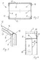
- eine perspektivische Ansicht einer modularen Karosserie- und Wandstruktur mit dazu passenden Fensterrahmen,
- Fig. 2
- eine Ansicht eines Rahmens,
- Fig. 3
- eine perspektivische Detail-Ansicht einer Rahmenecke,
- Fig. 4
- eine Seitenansicht der Rahmenecke gemäß Fig. 3.
- Fig. 1
- a perspective view of a modular body and wall structure with matching window frames,
- Fig. 2
- a view of a frame,
- Fig. 3
- a detailed perspective view of a frame corner,
- Fig. 4
- 3 shows a side view of the frame corner according to FIG. 3.
Nach Fig. 1 ist eine Wandstruktur 1 -hier ein Seitenwandabschnitt eines doppelstöckigen
Eisenbahn-Reisezugwagens- modular aus Modulelementen 2 mit längsorientierten
Trennfugen aufgebaut. Ihre Form und Kontur wird wesentlich von Säulen
oder Spanten 3 bestimmt. Deren Enden sind durch längs der Trennfugen aneinander
gelegte Randprofile 4 miteinander verbunden. Nicht näher dargestellte Verbindungselemente
legen die Module an den Enden von aneinanderstoßenden Spantabschnitten
aneinander fest. So werden umlaufende Säulen aus aufeinanderfolgenden Spantabschnitten
gebildet. 1 , a wall structure 1 - here a side wall section of a double-decker railway passenger car - is constructed modularly from
Die Spanten 3, die Randprofile 4 und längsorientierte Pfetten 5 bilden Auflageflächen
für eine hier nicht dargestellte Außenhaut-Beblechung. The
Im Oberstockbereich hat die Wandstruktur 1 eine an das Lichtraumprofil angepaßte,
gekrümmte Kontur. Die formgebende Krümmung im Längsverlauf der betreffenden
Spantabschnitte wird vollmechanisiert durch CNC-gesteuertes Rollbiegen erzeugt.In the upper floor area, the
Zwischen bestimmten Spant-Paaren 3 sind Fensterausschnitte 6 zum Einbau von
Fenstern (oder auch Klappen) vorgesehen, die im Oberstockbereich innerhalb der
gekrümmten Fläche liegen. In diese werden Rahmen 7 einzusetzen sein, um Auflageflächen
für eine Verglasung oder die erwähnten Klappen zu bilden. Der Abstand der
Spanten 3 voneinander bestimmt direkt die maximale Fenster- oder Klappenbreite.Between certain pairs of
Die erwähnte hochflexible Fertigungsweise der Spanten soll auch bei den Rahmen 7
angewendet werden. Diese bestehen, wie aus Fig. 2 besser ersichtlich ist, im Ausführungsbeispiel
aus je zwei parallelen Längsholmen 8 und Querholmen 9, die in den
Eckbereichen des Rahmens 7 an Querschnittsüberlappungen miteinander kaltgefügt
sind, wie noch näher zu beschreiben sein wird. Als Verbindungsmittel werden bevorzugt
Blindnieten verwendet, die in vorgebohrte Löcher einsetzbar und dann festspannbar
sind.The above-mentioned highly flexible production method of the frames should also be used for the
Die im Einbauzustand parallel zu den Spanten 3 verlaufenden, hochstehenden Querholme
9 der Rahmen bestehen aus geschlossenem Hohlprofil- oder Rohrmaterial ohne
seitlich auskragende Stege. Dieses erlaubt eine von unerwünschten Querschnittänderungen
weitestgehend freie Kaltverformung des Längsverlaufs, insbesondere durch
Rollbiegen. Der Querschnitt der Querholme ist etwas flacher als der Spantquerschnitt,
weil durch die Dickendifferenz die Einsenkung der Auflagefläche für die Verglasung
gegenüber der Außenhaut direkt vorgegeben wird. Wenn die Fensterpakete
verklebt werden sollen, so muß die Querschnittsbreite hierfür hinreichend breit sein.The upright crossbars that run parallel to the
Eine denkbare Befestigungsalternative -unter anderen- ist, die Fensterpakete von
einer Seite auf den Rahmen 7 aufzulegen und von dessen anderer Seite her mit
Schrauben oder dgl. lösbar zu befestigen. Auch dann bildet der Rahmen die Auflagefläche,
seine Holme können jedoch evtl. weniger breit sein als bei der Verklebungslösung.A conceivable fastening alternative - among others - is the window package from
one side on the
Ebenso wie die Spanten werden die Querholme maßgenau -vorzugsweise durch Laserschneiden- aus dem Rohmaterial abgelängt und dann nach Bedarf in die gewünschte Krümmung gebogen. Danach können zur Gewichtsminderung noch Ausnehmungen in die in die nicht als Auflagefläche der Verglasung dienenden Wandteile der Querholme eingebracht werden, vorzugsweise wieder durch Laserschneiden. Im gleichen Arbeitsgang werden schon die Löcher zum Durchstecken der Blindnieten hergestellt. Just like the frames, the cross bars are dimensionally accurate - preferably through Laser cutting - cut from the raw material and then into the desired curvature bent. Thereafter, recesses can be made to reduce weight into the wall parts that do not serve as the supporting surface for the glazing the crossbars are introduced, preferably again by laser cutting. in the The holes for inserting the blind rivets are the same step manufactured.
Die Längsholme 8 des Rahmens 7 haben demgegenüber im wesentlichen einen durch
Abkanten aus Blech erzeugten U-Querschnitt. Jeweils einer der beiden parallelen
Schenkel ist ein Teil der Auflagefläche des Rahmens 7. Dieser Schenkel ist wiederum
hinreichend breit zum sicheren Aufkleben der Verglasung zu dimemsionieren.In contrast, the
Beide Enden der Längsholme 8 sind einstückig mit Anschlußflächen oder -elementen
10 versehen. Diese sind ersichtlich höher als die Schenkel des restlichen U-Querschnitts.
Im Übergangsbereich sieht man deshalb zum Vermeiden von Kerbwirkungen
und zum Erhöhen der Schubsteifigkeit des Rahmens 7 Rundungsflächen 11 vor, die
an den Ecken in den rechteckigen freien Rahmenquerschnitt hineinragen können.Both ends of the
Die Längsholme 8 können aus Blechplatinen (mit Laser) ausgeschnitten werden, wobei
in einem Arbeitsgang die besagten Anschluß- und Rundungsflächen und ggf.
Löcher zum Durchstecken von Verbindungselementen wie Schrauben, Nieten oder
Schließringbolzen erzeugt werden. Anschließend werden sie durch Abkanten in ihre
Endform gebracht.The
In einer anderen, hier nicht gezeigten Ausführungsform können die Längsholme aber
auch, wie schon eingangs erwähnt, als Formteile mit allen notwendigen Durchbrüchen
und Bohrungen aus faserverstärktem Kunststoff hergestellt werden, so daß
daraus ein werkstoffhybrider Rahmen 7 entsteht.In another embodiment, not shown here, the longitudinal bars can
also, as already mentioned at the beginning, as molded parts with all the necessary openings
and holes are made of fiber reinforced plastic, so that
this creates a
Fig. 3 und 4 verdeutlichen eine mögliche Ausführung der Eckverbindungen zwischen
den Längs- und Querholmen eines Rahmens und die Lagebeziehung des eingebauten
Rahmens 7 zu den Spanten 3. Man erkennt, daß die lichte Weite des U-Querschnitts
des Längsholms 8 etwa der Höhe oder Dicke des Rohrquerschnitts des Querholms 9
entspricht. Zum Auflegen und Verkleben einer Verglasung muß jedoch die von den
Vorderseiten der Längs- und Querholme gebildete umlaufende Auflagefläche F
möglichst glatt (je nach Bedarf eben oder gekrümmt) sein. 3 and 4 illustrate a possible embodiment of the corner connections between the longitudinal and transverse spars of a frame and the positional relationship of the built-in
Auf der Vorderseite des Rahmens 7 sollte es deshalb in den Eckbereichen keine
Materialüberlappung geben. Statt dessen sieht man, wie hier dargestellt, eine Aussparung
in der Vorderseite des Querholms 9 vor, welche von dem in gleicher Ebene
liegenden U-Schenkelende des Längsholms 8 abgedeckt wird. Diese Lösung hat den
Vorteil, daß die Schenkel-Endfläche sich noch auf den verbleibenden Stirnflächen desOn the front of the
Rohrprofil-Querschnitts abstützen und im Bedarfsfall mit diesen -vorzugsweise per Laser- verschweißt werden kann.Support the cross-section of the tubular profile and, if necessary, preferably with it Can be laser welded.
Man könnte aber auch das Ende des vorderen U-Schenkels wegschneiden und den entsprechenden Abschnitt des Rohrprofils belassen.But you could also cut away the end of the front U-leg and that leave the corresponding section of the pipe profile.
Auf der Rückseite wird dagegen die Innenseite des rückwärtigen U-Schenkels des
Längsholms 8 an die Rückseite des Querholms 9 angelegt. An dieser Querschnittsüberlappung
werden die Einzelteile des Rahmens 7, wie schon erwähnt, miteinander
durch Nieten oder dgl. verbunden, wie hier durch strichpunktierte Linien angedeutet
ist.On the other hand, the inside of the rear U-leg of the
Die seitliche Positionierung des Rahmens 7 an der Wandstruktur ist, wie schon erwähnt,
durch die Spanten 3 bzw. deren Abstand voneinander vorgegeben. Zur
Höhenpositionierung des Rahmens 7 an der Wandstruktur sind im Ausführungsbeispiel
Winkelschienen 12 vorgesehen, die sich entlang den Längsholmen 8 des
Rahmens 7 erstrecken. Die Winkelschienen 12 können über einen vom Rahmen 7 abragenden Schenkel 13
vor der Montage des Rahmens 7 an der Außenhaut und/oder an den Säulen 3 befestigt werden.
Gegen ihren anderen Schenkel 14 wird der jeweilige U-Steg des Längsholms 8
angelegt und wiederum mit Nieten oder dgl. fest angebunden.As already mentioned, the lateral positioning of the
An die Stelle der hier gezeigten Winkelschienen können aber ggf. auch sonstige längslaufende Profile treten, die ohnehin in der Gerippestruktur vorzusehen sind. Diese können dann auch andere Querschnittsformen haben, z. B. als Rohrprofile ausgeführt sein.Instead of the angle rails shown here, other ones may also be used longitudinal profiles occur, which are to be provided in the framework structure anyway. These can then also have other cross-sectional shapes, e.g. B. as tube profiles be executed.
Das Maß D in Fig. 4 bezeichnet also die Dicke der auf den Rahmen 7 einzusetzenden
Verglasung oder Klappe inclusive einer Klebschicht- oder Dichtungsdicke und der
Dicke der hier angedeuteten Außenhaut 15. Dasselbe Maß D bezeichnet auch
annähernd die Differenz zwischen der Dicke der Querholme 9 des Rahmens 7 und
der Spanten 3, deren jeweilige Rückseiten mittels der Anschlußflächen 10
flächenbündig ausgerichtet sind. Man kann also die Einsenkung der Auflagefläche F
gegenüber der Außenhautfläche sehr einfach durch eine entsprechende Wahl der
Abmessungen der Spanten und Querholme definieren. Ein Toleranzausgleich ist an
dieser Stelle grundsätzlich nicht mehr notwendig. Bedarfsweise können geringfügige
Maßabweichungen durch Vorgabe einer Klebschichtdicke ausgeglichen werden.The dimension D in FIG. 4 thus denotes the thickness of those to be inserted on the
Die zum Rahmen 7 hin gerichteten Seitenflächen der Spanten 3 bilden in der gesamten
Einbauanordnung die seitlichen Begrenzungs- bzw. Anlageflächen für die Verglasung,
die nach dem Befestigen des Rahmens 7 an der Wandstruktur 1 anzubringen
ist. Entsprechend bilden die -etwa waagerechten- Schenkel 14 der Winkelprofile 12
die oberen bzw. unteren Anlageflächen. Auf Materialdoppelungen in Gestalt von
zusätzlichen Stegen an den Rahmenbauteilen kann verzichtet werden.The side surfaces of the
Die notwendige Positionsgenauigkeit und Reproduzierbarkeit wird mit der erwähnten
modularen Bauweise und der hochpräzisen Einzelteilfertigung der Wandstruktur 1
sichergestellt. Es ist ohne großen Aufwand möglich, in die Spanten 3 beidseits der
Fensterausschnitte 6 schon bei deren Herstellung Positionsmarken für das Anlegen
und Befestigen der Winkelprofile 12 einzubringen, so daß auch die Höhenlage der
Fensterausschnitte rationell und eindeutig vorgegeben ist.The necessary position accuracy and reproducibility is mentioned with the
modular design and high-precision single part production of the
Es versteht sich, daß man beim Einsetzen einer Verglasung in einen fertig mit
Rahmen 7 ausgestatteten Fensterausschnitt 6 der Wandstruktur durch Montagehilfen
-z. B. Distanzstücke- ein schnelles Ausrichten unterstützen wird. Das Verglasungspaket
wird allseits einen geringen Spalt zu den erwähnten Anlageflächen an
Spanten und Winkelprofilen einhalten, der nach dem Abbinden der Verklebung mit
dem Rahmen 7 durch eine dauerelastische Dichtmasse ausgefüllt wird.It goes without saying that when you put a glazing in one you are done with
Claims (6)
- Wall structure (1) with frame (7) comprising profiled-section parts (8, 9) and, for connecting these parts to one another, cold-joinable connecting means for attaching a flat element to the wall structure (1), characterized in that the profiled-section parts (8, 9), by means of connection elements (10) formed integrally on them, can be laid onto the wall structure (1), which is designed to be of a given thickness, from one side of this structure, a difference in thickness between the frame (7) and the wall structure (1) resulting in a clearly defined recessing (D) of a bearing surface (7) for the flat element relative to the opposite side of the wall structure (1).
- Wall structure (1) with frame (7) according to Claim 1, characterized in that the profiled-section parts (8, 9) form a support surface (F) for supporting the flat element without lateral webs, lateral bearing or boundary surfaces for positioning the flat element being formed directly by adjacent components (3, 12, 14) of the wall structure (1).
- Wall structure (1) with frame (7) according to Claim 1 or 2, characterized in that profiled-section parts (9) which are to be adapted to a wall structure (1) of curved contour comprise a continuous hollow profiled section which can be cold-formed into a predetermined curvature without any change in the cross section.
- Wall structure (1) with frame (7) according to one of the preceding claims, comprising longitudinal and transverse bars (8, 9) which are joined at cross-sectional overlaps by cold-joined connections.
- Wall structure (1) with frame (7) according to one of the preceding claims, characterized in that the profiled-section parts (8) which are not to be subjected to any cold-forming consist of fibre-reinforced plastic.
- Wall structure (1) with frame (7) according to one of the preceding claims, characterized in that the longitudinal bars (8) are designed to be U-shaped in cross section, with connection elements (10) provided at the ends.
Applications Claiming Priority (3)
| Application Number | Priority Date | Filing Date | Title |
|---|---|---|---|
| DE19708840A DE19708840C2 (en) | 1997-03-05 | 1997-03-05 | Frame for fastening surface elements |
| DE19708840 | 1997-03-05 | ||
| PCT/DE1998/000471 WO1998039190A1 (en) | 1997-03-05 | 1998-02-18 | Frame for fastening flat elements |
Publications (2)
| Publication Number | Publication Date |
|---|---|
| EP0964807A1 EP0964807A1 (en) | 1999-12-22 |
| EP0964807B1 true EP0964807B1 (en) | 2001-08-29 |
Family
ID=7822228
Family Applications (1)
| Application Number | Title | Priority Date | Filing Date |
|---|---|---|---|
| EP98912261A Expired - Lifetime EP0964807B1 (en) | 1997-03-05 | 1998-02-18 | Frame for fastening flat elements |
Country Status (4)
| Country | Link |
|---|---|
| EP (1) | EP0964807B1 (en) |
| AT (1) | ATE204818T1 (en) |
| DE (2) | DE19708840C2 (en) |
| WO (1) | WO1998039190A1 (en) |
Cited By (11)
| Publication number | Priority date | Publication date | Assignee | Title |
|---|---|---|---|---|
| DE10248654B4 (en) * | 2002-10-18 | 2007-02-22 | Daimlerchrysler Ag | Method for producing a motor vehicle body and motor vehicle body |
| CN106274937A (en) * | 2016-10-21 | 2017-01-04 | 苏州大成电子科技有限公司 | The panorama of a kind of high security sees railway car |
| CN106347391A (en) * | 2016-10-21 | 2017-01-25 | 苏州大成电子科技有限公司 | High-strength full-landscape train carriage |
| CN106364502A (en) * | 2016-10-18 | 2017-02-01 | 苏州大成电子科技有限公司 | Full-view tourist train compartment |
| CN106364507A (en) * | 2016-10-21 | 2017-02-01 | 苏州大成电子科技有限公司 | Full-landscape train compartment with good light transmission property |
| CN106379352A (en) * | 2016-10-18 | 2017-02-08 | 苏州大成电子科技有限公司 | Full-view carriage |
| CN106394572A (en) * | 2016-10-21 | 2017-02-15 | 苏州大成电子科技有限公司 | Wear-resisting panoramic train carriage |
| CN106428069A (en) * | 2016-10-18 | 2017-02-22 | 苏州大成电子科技有限公司 | Panoramic travel carriage |
| CN106497158A (en) * | 2016-10-21 | 2017-03-15 | 苏州大成电子科技有限公司 | A kind of panorama of environmental protection sees railway car |
| CN106494438A (en) * | 2016-10-21 | 2017-03-15 | 苏州大成电子科技有限公司 | A kind of good panorama of sight sees railway car |
| CN106627614A (en) * | 2016-10-21 | 2017-05-10 | 苏州大成电子科技有限公司 | Water-proof and oil-proof all-landscape train carriage |
Families Citing this family (3)
| Publication number | Priority date | Publication date | Assignee | Title |
|---|---|---|---|---|
| DE10051919A1 (en) * | 2000-10-19 | 2002-05-02 | Alstom Lhb Gmbh | Window installation system for vehicles |
| DE102017216908A1 (en) * | 2017-09-25 | 2019-03-28 | Siemens Mobility GmbH | Window device for a rail vehicle |
| CN110667619A (en) * | 2019-10-22 | 2020-01-10 | 中铁轨道交通装备有限公司 | Articulated high-floor tramcar side wall structure |
Family Cites Families (5)
| Publication number | Priority date | Publication date | Assignee | Title |
|---|---|---|---|---|
| EP0347132A3 (en) * | 1988-06-13 | 1991-02-27 | Hitachi, Ltd. | Car body for railway rolling stock |
| GB2257190A (en) * | 1991-05-25 | 1993-01-06 | Heywood Williams Ltd | Vehicle panel assembly, preferably for glazing |
| FR2679592A1 (en) * | 1991-07-12 | 1993-01-29 | Klein Ets Georges | GLAZING, PARTICULARLY FOR RAILWAY OR ROAD VEHICLE WINDOW. |
| GB2275290A (en) * | 1993-02-19 | 1994-08-24 | Jenbacher Transportsysteme | Window frame |
| DE19619617C1 (en) * | 1996-05-15 | 1997-07-03 | Waggonfabrik Talbot Gmbh & Co | Modular component for composite structure |
-
1997
- 1997-03-05 DE DE19708840A patent/DE19708840C2/en not_active Expired - Fee Related
-
1998
- 1998-02-18 AT AT98912261T patent/ATE204818T1/en not_active IP Right Cessation
- 1998-02-18 WO PCT/DE1998/000471 patent/WO1998039190A1/en active IP Right Grant
- 1998-02-18 DE DE59801311T patent/DE59801311D1/en not_active Expired - Fee Related
- 1998-02-18 EP EP98912261A patent/EP0964807B1/en not_active Expired - Lifetime
Cited By (11)
| Publication number | Priority date | Publication date | Assignee | Title |
|---|---|---|---|---|
| DE10248654B4 (en) * | 2002-10-18 | 2007-02-22 | Daimlerchrysler Ag | Method for producing a motor vehicle body and motor vehicle body |
| CN106364502A (en) * | 2016-10-18 | 2017-02-01 | 苏州大成电子科技有限公司 | Full-view tourist train compartment |
| CN106379352A (en) * | 2016-10-18 | 2017-02-08 | 苏州大成电子科技有限公司 | Full-view carriage |
| CN106428069A (en) * | 2016-10-18 | 2017-02-22 | 苏州大成电子科技有限公司 | Panoramic travel carriage |
| CN106274937A (en) * | 2016-10-21 | 2017-01-04 | 苏州大成电子科技有限公司 | The panorama of a kind of high security sees railway car |
| CN106347391A (en) * | 2016-10-21 | 2017-01-25 | 苏州大成电子科技有限公司 | High-strength full-landscape train carriage |
| CN106364507A (en) * | 2016-10-21 | 2017-02-01 | 苏州大成电子科技有限公司 | Full-landscape train compartment with good light transmission property |
| CN106394572A (en) * | 2016-10-21 | 2017-02-15 | 苏州大成电子科技有限公司 | Wear-resisting panoramic train carriage |
| CN106497158A (en) * | 2016-10-21 | 2017-03-15 | 苏州大成电子科技有限公司 | A kind of panorama of environmental protection sees railway car |
| CN106494438A (en) * | 2016-10-21 | 2017-03-15 | 苏州大成电子科技有限公司 | A kind of good panorama of sight sees railway car |
| CN106627614A (en) * | 2016-10-21 | 2017-05-10 | 苏州大成电子科技有限公司 | Water-proof and oil-proof all-landscape train carriage |
Also Published As
| Publication number | Publication date |
|---|---|
| DE59801311D1 (en) | 2001-10-04 |
| WO1998039190A1 (en) | 1998-09-11 |
| DE19708840C2 (en) | 1999-04-08 |
| EP0964807A1 (en) | 1999-12-22 |
| ATE204818T1 (en) | 2001-09-15 |
| DE19708840A1 (en) | 1998-09-17 |
Similar Documents
| Publication | Publication Date | Title |
|---|---|---|
| EP0608761B1 (en) | Coach bodywork, especially for railways | |
| EP0916534B1 (en) | Construction of a vehicle door | |
| DE102007036366B4 (en) | Vehicle roof with a roof module | |
| EP0964807B1 (en) | Frame for fastening flat elements | |
| EP0461345A1 (en) | Body for a motor vehicle, especially for a passenger car | |
| EP1911662B1 (en) | Vehicle body base and a platform system | |
| EP2030877B1 (en) | Vehicle frame with roof element | |
| DE102010014962A1 (en) | Exterior wall for a rail vehicle body and method for its production | |
| DE19612342C1 (en) | Construction for vehicle, esp. side wall | |
| EP0501226B1 (en) | Car body for vehicles and procedure of its manufacture | |
| DE102008021224B4 (en) | track vehicle | |
| EP2559609B1 (en) | Reinforcement frame and method for applying a reinforcement frame in a vehicle body | |
| EP1108640B1 (en) | Roof connection for motor cars | |
| DE20211949U1 (en) | Door for motor vehicles and connection of the edges of motor vehicle door panels | |
| DE976897C (en) | Car body for cars and similar vehicles | |
| DE19628305A1 (en) | Rail vehicle | |
| DE19946013B4 (en) | Side frame for a self-supporting body of a motor vehicle | |
| EP0855978A1 (en) | Modular element and manufacturing process | |
| DE9307052U1 (en) | Wall plate for vehicle bodies | |
| DE69501392T2 (en) | CAR BOX | |
| DE19538793C2 (en) | Module element | |
| DE3610769C2 (en) | ||
| DE4330014A1 (en) | Motor vehicle, in particular van | |
| DE3424690C2 (en) | Self-supporting bus body | |
| EP1296867B1 (en) | Planar element and method for producing a planar element |
Legal Events
| Date | Code | Title | Description |
|---|---|---|---|
| PUAI | Public reference made under article 153(3) epc to a published international application that has entered the european phase |
Free format text: ORIGINAL CODE: 0009012 |
|
| 17P | Request for examination filed |
Effective date: 19990115 |
|
| AK | Designated contracting states |
Kind code of ref document: A1 Designated state(s): AT BE CH DE FI FR IT LI SE |
|
| GRAG | Despatch of communication of intention to grant |
Free format text: ORIGINAL CODE: EPIDOS AGRA |
|
| GRAG | Despatch of communication of intention to grant |
Free format text: ORIGINAL CODE: EPIDOS AGRA |
|
| GRAH | Despatch of communication of intention to grant a patent |
Free format text: ORIGINAL CODE: EPIDOS IGRA |
|
| 17Q | First examination report despatched |
Effective date: 20010202 |
|
| GRAH | Despatch of communication of intention to grant a patent |
Free format text: ORIGINAL CODE: EPIDOS IGRA |
|
| GRAA | (expected) grant |
Free format text: ORIGINAL CODE: 0009210 |
|
| AK | Designated contracting states |
Kind code of ref document: B1 Designated state(s): AT BE CH DE FI FR IT LI SE |
|
| PG25 | Lapsed in a contracting state [announced via postgrant information from national office to epo] |
Ref country code: IT Free format text: LAPSE BECAUSE OF FAILURE TO SUBMIT A TRANSLATION OF THE DESCRIPTION OR TO PAY THE FEE WITHIN THE PRE;WARNING: LAPSES OF ITALIAN PATENTS WITH EFFECTIVE DATE BEFORE 2007 MAY HAVE OCCURRED AT ANY TIME BEFORE 2007. THE CORRECT EFFECTIVE DATE MAY BE DIFFERENT FROM THE ONE RECORDED.SCRIBED TIME-LIMIT Effective date: 20010829 Ref country code: FR Free format text: LAPSE BECAUSE OF FAILURE TO SUBMIT A TRANSLATION OF THE DESCRIPTION OR TO PAY THE FEE WITHIN THE PRESCRIBED TIME-LIMIT Effective date: 20010829 Ref country code: FI Free format text: LAPSE BECAUSE OF FAILURE TO SUBMIT A TRANSLATION OF THE DESCRIPTION OR TO PAY THE FEE WITHIN THE PRESCRIBED TIME-LIMIT Effective date: 20010829 |
|
| REF | Corresponds to: |
Ref document number: 204818 Country of ref document: AT Date of ref document: 20010915 Kind code of ref document: T |
|
| RIN1 | Information on inventor provided before grant (corrected) |
Inventor name: ZIMMERMANN, MICHAEL |
|
| REG | Reference to a national code |
Ref country code: CH Ref legal event code: EP |
|
| REF | Corresponds to: |
Ref document number: 59801311 Country of ref document: DE Date of ref document: 20011004 |
|
| PG25 | Lapsed in a contracting state [announced via postgrant information from national office to epo] |
Ref country code: SE Free format text: LAPSE BECAUSE OF FAILURE TO SUBMIT A TRANSLATION OF THE DESCRIPTION OR TO PAY THE FEE WITHIN THE PRESCRIBED TIME-LIMIT Effective date: 20011129 |
|
| EN | Fr: translation not filed | ||
| PG25 | Lapsed in a contracting state [announced via postgrant information from national office to epo] |
Ref country code: AT Free format text: LAPSE BECAUSE OF NON-PAYMENT OF DUE FEES Effective date: 20020218 |
|
| PG25 | Lapsed in a contracting state [announced via postgrant information from national office to epo] |
Ref country code: LI Free format text: LAPSE BECAUSE OF NON-PAYMENT OF DUE FEES Effective date: 20020228 Ref country code: CH Free format text: LAPSE BECAUSE OF NON-PAYMENT OF DUE FEES Effective date: 20020228 Ref country code: BE Free format text: LAPSE BECAUSE OF NON-PAYMENT OF DUE FEES Effective date: 20020228 |
|
| PLBE | No opposition filed within time limit |
Free format text: ORIGINAL CODE: 0009261 |
|
| STAA | Information on the status of an ep patent application or granted ep patent |
Free format text: STATUS: NO OPPOSITION FILED WITHIN TIME LIMIT |
|
| 26N | No opposition filed | ||
| BERE | Be: lapsed |
Owner name: TALBOT G.M.B.H. & CO. K.G. Effective date: 20020228 |
|
| PG25 | Lapsed in a contracting state [announced via postgrant information from national office to epo] |
Ref country code: DE Free format text: LAPSE BECAUSE OF NON-PAYMENT OF DUE FEES Effective date: 20020903 |
|
| REG | Reference to a national code |
Ref country code: CH Ref legal event code: PL |