EP0608559B1 - Lichtbandleuchte - Google Patents
Lichtbandleuchte Download PDFInfo
- Publication number
- EP0608559B1 EP0608559B1 EP93120902A EP93120902A EP0608559B1 EP 0608559 B1 EP0608559 B1 EP 0608559B1 EP 93120902 A EP93120902 A EP 93120902A EP 93120902 A EP93120902 A EP 93120902A EP 0608559 B1 EP0608559 B1 EP 0608559B1
- Authority
- EP
- European Patent Office
- Prior art keywords
- reflector
- heat
- light strip
- lamp
- cable
- Prior art date
- Legal status (The legal status is an assumption and is not a legal conclusion. Google has not performed a legal analysis and makes no representation as to the accuracy of the status listed.)
- Expired - Lifetime
Links
- 239000002184 metal Substances 0.000 claims description 6
- 210000002105 tongue Anatomy 0.000 claims 2
- 239000000463 material Substances 0.000 claims 1
- 229920000915 polyvinyl chloride Polymers 0.000 description 4
- 239000004800 polyvinyl chloride Substances 0.000 description 4
- 238000010616 electrical installation Methods 0.000 description 2
- 238000009434 installation Methods 0.000 description 2
- 238000004519 manufacturing process Methods 0.000 description 2
- 239000007858 starting material Substances 0.000 description 2
- 238000005452 bending Methods 0.000 description 1
- 230000002349 favourable effect Effects 0.000 description 1
- 230000020169 heat generation Effects 0.000 description 1
- 238000009413 insulation Methods 0.000 description 1
- 230000007257 malfunction Effects 0.000 description 1
Images


Classifications
-
- F—MECHANICAL ENGINEERING; LIGHTING; HEATING; WEAPONS; BLASTING
- F21—LIGHTING
- F21V—FUNCTIONAL FEATURES OR DETAILS OF LIGHTING DEVICES OR SYSTEMS THEREOF; STRUCTURAL COMBINATIONS OF LIGHTING DEVICES WITH OTHER ARTICLES, NOT OTHERWISE PROVIDED FOR
- F21V31/00—Gas-tight or water-tight arrangements
-
- F—MECHANICAL ENGINEERING; LIGHTING; HEATING; WEAPONS; BLASTING
- F21—LIGHTING
- F21S—NON-PORTABLE LIGHTING DEVICES; SYSTEMS THEREOF; VEHICLE LIGHTING DEVICES SPECIALLY ADAPTED FOR VEHICLE EXTERIORS
- F21S4/00—Lighting devices or systems using a string or strip of light sources
- F21S4/20—Lighting devices or systems using a string or strip of light sources with light sources held by or within elongate supports
-
- F—MECHANICAL ENGINEERING; LIGHTING; HEATING; WEAPONS; BLASTING
- F21—LIGHTING
- F21V—FUNCTIONAL FEATURES OR DETAILS OF LIGHTING DEVICES OR SYSTEMS THEREOF; STRUCTURAL COMBINATIONS OF LIGHTING DEVICES WITH OTHER ARTICLES, NOT OTHERWISE PROVIDED FOR
- F21V27/00—Cable-stowing arrangements structurally associated with lighting devices, e.g. reels
-
- F—MECHANICAL ENGINEERING; LIGHTING; HEATING; WEAPONS; BLASTING
- F21—LIGHTING
- F21Y—INDEXING SCHEME ASSOCIATED WITH SUBCLASSES F21K, F21L, F21S and F21V, RELATING TO THE FORM OR THE KIND OF THE LIGHT SOURCES OR OF THE COLOUR OF THE LIGHT EMITTED
- F21Y2103/00—Elongate light sources, e.g. fluorescent tubes
Definitions
- the invention relates to a light band luminaire with a special power cable bushing according to the preamble of claim 1.
- the invention is therefore based on the object of developing a continuous line luminaire of the type mentioned in such a way that ordinary mains cables (for example cables with PVC insulation) can be passed through in the interior.
- ordinary mains cables for example cables with PVC insulation
- the invention is characterized by the technical teaching of claim 1.
- An essential feature of the invention is that a commercially available power cord is now laid next to the side wall of the lamp above the reflector.
- the wiring according to the invention i.e. the implementation of a power cord in the interior of the luminaire in a zone that is not subject to a lot of heat can be used for all known continuous-row luminaires.
- light band lights in a closed design are preferred, in which such heat problems arise particularly noticeably.
- the power cord is laid in a downward longitudinal groove or receptacle of the reflector, because here a particularly favorable position securing of the power cord is ensured.
- the downward-looking longitudinal groove ensures that this area of the reflector comes even more strongly into the cooler area of the lamp than if the groove were not present and is therefore even less exposed to heat.
- the groove with its side walls shields the power cable laid at the base of the groove from part of the radiant heat which is generated in the lamp and which would otherwise hit the power cable unprotected.
- brackets for the power cord are formed by bending sheet metal tabs out of the plane of the reflector in the region of the longitudinal groove, said tabs encompassing the power cord so as to form a to ensure correct installation of the power cord on the reflector.
- the lamp according to Figures 1,3 and 4 consists essentially of a base trough 1, which is attached to a mounting wall or ceiling via a mounting rail 2 ( Figure 2) or a corresponding ceiling mounting part 3 ( Figure 1).
- 1 and 3 is a two-lamp version, the lamp according to FIG. 2 is single-lamp.
- Snap flaps 18 are formed on the inside of the base trough 1, which reach through corresponding openings 19 (see FIG. 4) in the reflector 5 and hold it.
- the reflector has bends 20 on its outer edges, which rest on associated support ribs on the base trough.
- a ballast 10 is attached to the reflector above the reflector 5.
- a clamp 17 is otherwise arranged on the one side of the reflector ( Figure 4).
- the base trough 1 is connected to a lamp cover 12 via side closures 4, a moisture-protected design being shown in FIGS. 1 and 2.
- the illuminants 11 have corresponding lamp holders 13 on the end face and a starter 14 (FIG. 3) is also arranged above the reflector.
- the grommet 15 is advantageous through breakout openings stuck in the housing. Such breakout openings can be distributed over the entire base trough 1. Only the end user then breaks the openings that he needs for his electrical installation (similar to the breakout openings in junction boxes).
- the mounting in the area of the longitudinal groove takes place here by means of sheet metal brackets 16 which are bent up and out of the plane of the reflector.
- the internal wiring 9 of the lamp is also attached laterally above the reflector on the reflector and is also laid in a longitudinal groove 7 and is also held by sheet metal tabs 16.
- FIG. 4 shows that the entire length of the reflector 5 is pulled through with the conventional mains cable 8 and that the mains cable 8 is connected to a terminal 17 at the end of the reflector. From this terminal 17 then a further, commercially available power cable 8 extends, which is inserted through a corresponding grommet 15 into the adjacent strip light.
- the heat generation in such light band luminaires takes place from essentially two different heat sources.
- an important heat source is the illuminant itself, which emits its heat in the direction of the reflector as radiant heat.
- Another essential heat source is the so-called ballast.
- the greatest heat loads therefore arise in the upper area of the base trough 1 (that is to say when fastened to a ceiling).
- the invention therefore provides for the power cord to be removed from this area exposed to high heat and, if possible, to be guided laterally outside above the reflector, namely at the point where the coolest or least heat-affected zone is.
Landscapes
- Engineering & Computer Science (AREA)
- General Engineering & Computer Science (AREA)
- Arrangement Of Elements, Cooling, Sealing, Or The Like Of Lighting Devices (AREA)
- Eye Examination Apparatus (AREA)
- Laser Surgery Devices (AREA)
- Light Guides In General And Applications Therefor (AREA)
Description
- Die Erfindung betrifft eine Lichtbandleuchte mit einer besonderen Netzkabeldurchführung nach dem Oberbegriff des Patentanspruches 1.
- Bei derartigen Lichtbandleuchten wie z.B. in DE-U-8 620 254 offenbart, die geeignet sind, aneinander gereiht ein Lichtband an einer Decke oder an einer sonstigen Befestigungsfläche zu bilden, besteht das Problem, daß man die Leuchten untereinander verdrahten muß.
- Neben der hohen Wärmeentwicklung im Innenbereich der Leuchte konnten bisher direkte Netzkabeldurchführungen durch die Leuchte hindurch nicht vorgenommen werden, weil die Netzkabel den hohen Wärmebelastungen in der Leuchte nicht standhielten. Diese hohe Wärmebelastung resultiert vor allem daraus, daß es bisher selbstverständlich war, die Netzkabeldurchführung am Boden der Grundwanne zu führen.
- Man war deshalb gezwungen, entweder hochwärmefeste Netzkabel unter Aufwendung entsprechend hoher Kosten zu verwenden, oder man verwendete am Eingang und Ausgang jeder Lichtbandleuchte je eine Klemme, an welche das von außen kommende bzw. das nach außen führende Netzkabel angeschlossen wurde, wobei die beiden Klemmen durch die Lichtbandleuchte hindurch mit eigenen, speziellen hochwärmefesten Drähten oder Kabeln versorgt waren. Unter hochwärmefesten Drähten und Kabel werden solche verstanden, die nach der EN 60 598-1 mit einer höchsten zulässigen Grenztemperatur in Leuchten von über 90° C belastet werden dürfen (z. B. wärmebeständiges PVC). Bei Standardelektroinstallationen wird jedoch nur gewöhnliches PVC (Polyvinylchlorid) verwendet, dessen höchste zulässige Grenztemperatur nach der zuvor genannten Norm bei 90° C liegt.
- Bei Verwendung hochwärmefesten Drähten oder Kabel besteht aber ein höherer Herstellungsaufwand und eine höhere Störanfälligkeit, weil dann die Einführung und Verdrahtung des Netzkabels an der Klemme, die Durchführung hochwärmefester Drähte oder Kabel durch den Innenraum der Leuchte und die Verbindung zur nächsten Leuchte auszuführen ist.
- Der Erfindung liegt deshalb die Aufgabe zugrunde, eine Lichtbandleuchte der eingangs genannten Art so weiterzubilden, daß im Innenraum gewöhnliche Netzkabel (z. B. Kabel mit PVC-Isolierung) hindurchgeführt werden können.
- Zur Lösung der gestellten Aufgabe ist die Erfindung durch die technische Lehre des Anspruches 1 gekennzeichnet.
- Wesentliches Merkmal der Erfindung ist, daß ein handelsübliches Netzkabel nun erfindungsgemäß oberhalb des Reflektors nächst zur Seitenwand der Leuchte verlegt ist.
- Damit besteht der wesentliche Vorteil, daß das Netzkabel in der am wenigsten wärmebelasteten Zone der Lichtbandleuchte verlegt wird und daher herkömmlich, nicht wärmefeste Netzkabel verwendet werden können. Damit ist weiterhin der Vorteil gegeben, daß auf eine der vorher erwähnten eingangs- und ausgangsseitig angeordneten Klemmen der Lichtbandleuchte verzichtet werden kann und die Netzkabel direkt durchverlegt werden können. Es genügt also die Anordnung einer einzigen Klemme pro Lichtbandleuchte, um dort die erforderliche Verdrahtung mit der internen Verdrahtung der Lichtbandleuchte herzustellen.
- Damit besteht der Vorteil, daß der Benutzer (Endverbraucher) der Lichtbandleuchte diese Verdrahtung nun selbst herstellen kann und dabei gewöhnliche Netzkabel verwendet, was mit einer wesentlichen Verringerung des Installationsaufwandes verbunden ist.
- Außerdem werden die Herstellungskosten der Lichtbandleuchte geringer, weil auf eine hochwärmefeste Leuchtendurchgangs-Verdrahtung verzichtet werden kann.
- Die erfindungsgemäße Verdrahtung, d.h. die Durchführung eines Netzkabels im Leuchteninnenraum an einer wenig wärmebelasteten Zone kann für alle bekannten Lichtbandleuchten verwendet werden. Insbesondere werden Lichtbandleuchten in einer geschlossenen Ausführung bevorzugt, bei denen derartige Wärmeprobleme besonders fühlbar entstehen.
- Nach einem bevorzugten Merkmal der vorliegenden Erfindung ist es vorgesehen, daß das Netzkabel in einer nach unten gerichteten Längsnut oder Aufnahme des Reflektors verlegt ist, weil hier eine besonders günstige Lagesicherung des Netzkabels gewährleistet ist. Außerdem sorgt die nach unten gerichtete Längsnut dafür, daß dieser Bereich des Reflektors noch stärker in den kühleren Bereich der Leuchte kommt als wenn die Nut nicht vorhanden wäre und daher noch weniger wärmebelastet ist.
- Außerdem schirmt die Nut mit ihren Seitenwandungen das am Grund der Nut verlegte Netzkabel von einem Teil der Strahlungswärme ab, die in der Leuchte erzeugt wird und die sonst ungeschützt das Netzkabel treffen würde.
- Hierbei wird es bevorzugt, wenn Halterungen für das Netzkabel dadurch gebildet werden, daß aus der Ebene des Reflektors im Bereich der Längsnut Blechlaschen herausgebogen werden, welche das Netzkabel umgreifen, um so eine lagerichtige Montage des Netzkabels auf dem Reflektor zu gewährleisten.
- Weitere Merkmale der Erfindung sind Merkmale der übrigen Ansprüche.
- Der Erfindungsgegenstand der vorliegenden Erfindung ergibt sich nicht nur aus dem Gegenstand der einzelnen Patentansprüche, sondern auch aus der Kombination der einzelnen Patentansprüche untereinander.
Alle in den Unterlagen offenbarten Angaben und Merkmale, insbesondere die in den Zeichnungen dargestellte räumliche Ausbildung werden als erfindungswesentlich beansprucht soweit sie einzeln oder in Kombination gegenüber dem Stand der Technik neu sind. - Im folgenden wird die Erfindung anhand von mehrere Ausführungswege darstellenden Zeichnungen näher erläutert. Hierbei gehen aus den Zeichnungen und ihrer Beschreibung weitere wesentliche Merkmale und Vorteile der Erfindung hervor.
- Es zeigen:
- Figur 1:
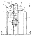
- einen Querschnitt durch eine Leuchte in einer ersten Ausführungsform gemäß der Linie I-I in Figur 3;
- Figur 2:
- einen Querschnitt durch eine andere Ausführungsform einer Leuchte;
- Figur 3:
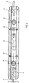
- einen Längsschnitt durch die Leuchte nach Figur
- Figur 4:
- eine Draufsicht auf den Reflektor mit Anordnung des Netzkabels für die Leuchte nach Figur 2.
- Die Leuchte nach den Figuren 1,3 und 4 besteht im wesentlichen aus einer Grundwanne 1, die über eine Tragschiene 2 (Figur2) oder über ein entsprechendes Deckenbefestigungsteil 3 (Figur 1) an einer Befestigungswand oder Decke befestigt wird. Während die Leuchte nach Figur 1 und 3 eine zweiflammige Ausführung ist, ist die Leuchte nach Figur 2 einflammig ausgeführt.
- An der Innenseite der Grundwanne 1 sind Schnapplappen 18 angeformt, welche durch entsprechende Öffnungen 19 (Vergleiche Figur 4) im Reflektor 5 hindurchgreifen und diesen halten. Außerdem weist der Reflektor an seinen Außenkanten Abbiegungen 20 auf, die auf zugeordneten Auflagerippen an der Grundwanne aufliegen.
- Oberhalb des Reflektors 5 ist ein Vorschaltgerät 10 auf dem Reflektor befestigt. An der einen Seite des Reflektors (Figur 4) ist im übrigen eine Klemme 17 angeordnet.
- Die Grundwanne 1 ist über seitliche Verschlüsse 4 mit einer Leuchtenabdeckung 12 verbunden, wobei in den Figuren 1 und 2 eine feuchtigkeitsgeschützte Ausführung gezeigt ist.
- Die Leuchtmittel 11 weisen entsprechende stirnseitige Lampenfassungen 13 auf und im übrigen ist oberhalb des Reflektors noch ein Starter 14 (Figur 3) angeordnet.
- Wichtig ist nun, daß ein Netzkabel e in einfacher, herkömmlicher und standardisierter Ausführung durch eine entsprechende Durchführungstülle 15 in die Grundwanne 1 eingeführt wird und dann im Bereich einer sich etwa über die gesamte Längsseite des Reflektors 5 erstreckenden Längsnut 6 verlegt ist.
- Die Durchführungstülle 15 wird vorteilhaft durch Ausbruchöffnungen im Gehäuse gesteckt. Derartige Ausbruchöffnungen können über die gesamte Grundwanne 1 verteilt werden. Erst der Endverbraucher bricht dann die Öffnungen, die er für seine Elektroinstallation benötigt, auf (ähnlich der Ausbruchöffnungen bei Verteilerdosen).
Die Halterung im Bereich der Längsnut erfolgt hierbei durch Blechlaschen 16, die aus der Ebene des Reflektors nach oben abgebogen und herausgebogen sind. - Ebenfalls ist wichtig, daß die interne Verdrahtung 9 der Leuchte ebenfalls seitlich oberhalb des Reflektors am Reflektor befestigt ist und ebenfalls in einer Längsnut 7 verlegt ist und gleichfalls durch Blechlaschen 16 gehalten ist.
- Die Figur 4 zeigt, daß die gesamte Länge des Reflektors 5 mit dem herkömmlichen Netzkabel 8 durchzogen ist und daß am Ende des Reflektors das Netzkabel 8 mit einer Klemme 17 verbunden wird. Von dieser Klemme 17 geht dann ein weiteres, handelsübliches Netzkabel 8 aus, welches durch eine entsprechende Durchführungstülle 15 in die benachbarte Lichtbandleuchte eingeführt ist. Die Wärmeerzeugung in derartigen Lichtbandleuchten erfolgt von im wesentlichen zwei verschiedenen Wärmequellen. Zum einen ist eine wichtige Wärmequelle das Leuchtmittel selbst, welches als Strahlungswärme seine Wärme in Richtung auf den Reflektor abgibt. Eine weitere wesentliche Wärmequelle ist das sogenannte Vorschaltgerät. Im oberen Bereich der Grundwanne 1 (also bei Befestigung an einer Decke) entstehen daher die größten Wärmebelastungen. Die Erfindung sieht deshalb vor, das Netzkabel aus diesem hochwärmebelasteten Bereich herauszunehmen und möglichst seitlich außen oberhalb des Reflektors zu führen, nämlich an der Stelle, wo die kühlste bzw. am wenigsten wärmebelastete Zone ist.
-
- 1
- Grundwanne
- 2
- Tragschiene
- 3
- Deckenbefestigungsteil
- 4
- Verschluß
- 5
- Reflektor
- 6
- Längsnut
- 7
- Längsnut
- 8
- Netzkabel
- 9
- interne Verdrahtung
- 10
- Vorschaltgerät
- 11
- Leuchtmittel
- 12
- Leuchtenabdeckung
- 13
- Lampenfassung
- 14
- Starter
- 15
- Durchführungstülle
- 16
- Blechlasche
- 17
- Klemme
- 18
- Schnapplappen
- 19
- Öffnung
- 20
- Abbiegung
Claims (5)
- Lichtbandleuchte mit einem Gehäuse (1) und mit wenigstens einem länglichen Leuchtenkörper (11), hinter dem ein Reflektor (5) angeordnet ist, sowie ggf. mit einem Vorschaltgerät (10), wobei der Reflektor (5) und der Leuchtkörper (11) von Bauteilen (1,12) umschlossen sind, dadurch gekennzeichnet, daß seitlich an der Rückseite des Reflektors (5) wenigstens eine Aufnahme (6,7) für ein gewöhnliches Netzkabel (8), z.B. gewöhnliches PVC-Kabel, sowie ggf. für eine innere Verdrahtung (9) vorgesehen ist.
- Lichtbandleuchte nach Anspruch 1, dadurch gekennzeichnet, daß das Netzkabel (8) über verteilt angeordnete Ausbruchöffnungen aus dem Gehäuse (1) heraus bzw. in das Gehäuse (1) hinein geführt ist.
- Lichtbandleuchte nach Anspruch 1 oder 2, dadurch gekennzeichnet, daß ein Teil der Aufnahme (6,7) durch eine entsprechende, gestufte Profilierung des Reflektors (5) ausgebildet ist.
- Lichtbandleuchte nach einem der Ansprüche 1 bis 3, dadurch gekennzeichnet, daß Blechlaschen (16) zum Halten des Netzkabels (8) bzw. der Verdrahtung (9) vorgesehen sind.
- Lichtbandleuchte nach Anspruch 4, dadurch gekennzeichnet, daß die Blechlaschen (16) aus dem Material des Reflektors (5) herausgebogen sind.
Applications Claiming Priority (2)
| Application Number | Priority Date | Filing Date | Title |
|---|---|---|---|
| DE9300896U DE9300896U1 (de) | 1993-01-23 | 1993-01-23 | Lichtbandleuchte |
| DE9300896U | 1993-01-23 |
Publications (2)
| Publication Number | Publication Date |
|---|---|
| EP0608559A1 EP0608559A1 (de) | 1994-08-03 |
| EP0608559B1 true EP0608559B1 (de) | 1997-03-05 |
Family
ID=6888487
Family Applications (1)
| Application Number | Title | Priority Date | Filing Date |
|---|---|---|---|
| EP93120902A Expired - Lifetime EP0608559B1 (de) | 1993-01-23 | 1993-12-24 | Lichtbandleuchte |
Country Status (4)
| Country | Link |
|---|---|
| EP (1) | EP0608559B1 (de) |
| AT (1) | ATE149660T1 (de) |
| DE (2) | DE9300896U1 (de) |
| ES (1) | ES2101208T3 (de) |
Families Citing this family (3)
| Publication number | Priority date | Publication date | Assignee | Title |
|---|---|---|---|---|
| DE4445164C2 (de) * | 1994-12-17 | 2002-03-07 | Ceag Sicherheitstechnik Gmbh | Sicherheits- und Rettungszeichenleuchte |
| DE202005019282U1 (de) * | 2005-12-09 | 2007-04-19 | Zumtobel Lighting Gmbh | Leuchte mit einem Leitungsaufnahmebereich zur Aufnahme von elektrischen Leitungen |
| DE102010062998B4 (de) * | 2010-12-14 | 2014-05-28 | Osram Gmbh | Leuchte mit einem rohrförmigen Leuchtenkorpus, Verfahren zum Herstellen einer derartigen Leuchte sowie ein Abstandselement |
Family Cites Families (6)
| Publication number | Priority date | Publication date | Assignee | Title |
|---|---|---|---|---|
| DD68039A (de) * | ||||
| DE1276816B (de) * | 1961-06-19 | 1968-09-05 | Wilden Elektro Bau | Leuchte fuer langgestreckte Entladungslampen |
| US3436537A (en) * | 1967-07-05 | 1969-04-01 | Edward T Bostonian | Fluorescent lighting fixture with wireways on the reflector |
| DE3302370A1 (de) * | 1983-01-17 | 1984-07-19 | Siemens AG, 1000 Berlin und 8000 München | Leuchte und verfahren zu ihrer montage |
| DE3346786A1 (de) * | 1983-12-23 | 1985-08-22 | Maschinenfabrik Georg Kiefer Gmbh, 7000 Stuttgart | Haengeleuchte |
| IT207643Z2 (it) * | 1986-03-11 | 1988-02-08 | Dil Srl | Elemento profilato a canali separati ed ispezionabili dall'estenro. |
-
1993
- 1993-01-23 DE DE9300896U patent/DE9300896U1/de not_active Expired - Lifetime
- 1993-12-24 DE DE59305628T patent/DE59305628D1/de not_active Expired - Fee Related
- 1993-12-24 AT AT93120902T patent/ATE149660T1/de not_active IP Right Cessation
- 1993-12-24 EP EP93120902A patent/EP0608559B1/de not_active Expired - Lifetime
- 1993-12-24 ES ES93120902T patent/ES2101208T3/es not_active Expired - Lifetime
Also Published As
| Publication number | Publication date |
|---|---|
| ES2101208T3 (es) | 1997-07-01 |
| DE59305628D1 (de) | 1997-04-10 |
| EP0608559A1 (de) | 1994-08-03 |
| DE9300896U1 (de) | 1994-02-24 |
| ATE149660T1 (de) | 1997-03-15 |
Similar Documents
| Publication | Publication Date | Title |
|---|---|---|
| DE3880470T2 (de) | Armatur fuer treibhausbeleuchtung. | |
| EP0574761B1 (de) | Wannenleuchte mit Reflektorkorb | |
| EP0798951B1 (de) | Konvertergehäuse | |
| DE69404743T2 (de) | Befestigungsvorrichtung für eine Leuchte | |
| DE9307862U1 (de) | Leuchtkörper für Leuchtreklamen | |
| EP0608559A1 (de) | Lichtbandleuchte | |
| EP0893860B1 (de) | Anschlussgarnitur für Leuchtstofflampen | |
| EP3531016B1 (de) | Lichtbandsystem mit elektrischem bauelement | |
| EP0551610A1 (de) | Einbaustrahler | |
| EP0648973B1 (de) | Leuchte | |
| DE102016104426A1 (de) | Modul für modulare Außenleuchte | |
| DE10241941B4 (de) | Leuchtensystem, Adaptionsglied und Leuchte damit | |
| DE2838528A1 (de) | Stromverteilungseinrichtung mit schnellanschluessen | |
| DE866212C (de) | Befestigungseinrichtung fuer elektrische Wandleuchten od. dgl. Installationsgeraete auf Wanddosen | |
| DE3014241A1 (de) | Vorrichtung zum verbinden von leuchten zu lichtbaendern bzw. lichtbandfiguren | |
| DE557735C (de) | Elektrische Leuchte mit gedichteter, in einem Befestigungsstutzen angeordneter Einfuehrung fuer wahlweise Verwendung als Decken-, Wand- oder Schraegleuchte | |
| DE202018101279U1 (de) | Beleuchtungsvorrichtung | |
| DE1534566A1 (de) | Beleuchtungseinrichtung fuer Strassen | |
| AT4313U1 (de) | Stromschiene | |
| DE8505922U1 (de) | Langgestreckte, einlampige deckenleuchte mit pendelrohraufhaengung | |
| DE1464169C (de) | Langfelddeckenleuchte mit einem über die Lange der Entladungslampe erstreckten, hohlpnsmatischen Trag und Anschlußgehause | |
| DE2019294A1 (de) | Aufbauleuchte fuer Leuchtstofflampen | |
| DE8431901U1 (de) | Montagevorrichtung für elektrische Installationsteile | |
| DE9312424U1 (de) | Leuchte | |
| EP1045405A1 (de) | Transformator, insbesondere elektronischer Transformator für Halogen-Deckeneinbaustrahler |
Legal Events
| Date | Code | Title | Description |
|---|---|---|---|
| PUAI | Public reference made under article 153(3) epc to a published international application that has entered the european phase |
Free format text: ORIGINAL CODE: 0009012 |
|
| AK | Designated contracting states |
Kind code of ref document: A1 Designated state(s): AT CH DE ES FR IT LI |
|
| 17P | Request for examination filed |
Effective date: 19941012 |
|
| 17Q | First examination report despatched |
Effective date: 19950516 |
|
| GRAG | Despatch of communication of intention to grant |
Free format text: ORIGINAL CODE: EPIDOS AGRA |
|
| GRAG | Despatch of communication of intention to grant |
Free format text: ORIGINAL CODE: EPIDOS AGRA |
|
| GRAH | Despatch of communication of intention to grant a patent |
Free format text: ORIGINAL CODE: EPIDOS IGRA |
|
| GRAH | Despatch of communication of intention to grant a patent |
Free format text: ORIGINAL CODE: EPIDOS IGRA |
|
| GRAA | (expected) grant |
Free format text: ORIGINAL CODE: 0009210 |
|
| AK | Designated contracting states |
Kind code of ref document: B1 Designated state(s): AT CH DE ES FR IT LI |
|
| REF | Corresponds to: |
Ref document number: 149660 Country of ref document: AT Date of ref document: 19970315 Kind code of ref document: T |
|
| REG | Reference to a national code |
Ref country code: CH Ref legal event code: EP |
|
| REF | Corresponds to: |
Ref document number: 59305628 Country of ref document: DE Date of ref document: 19970410 |
|
| REG | Reference to a national code |
Ref country code: CH Ref legal event code: NV Representative=s name: LUCHS & PARTNER PATENTANWAELTE |
|
| ET | Fr: translation filed | ||
| ITF | It: translation for a ep patent filed | ||
| REG | Reference to a national code |
Ref country code: ES Ref legal event code: FG2A Ref document number: 2101208 Country of ref document: ES Kind code of ref document: T3 |
|
| PLBE | No opposition filed within time limit |
Free format text: ORIGINAL CODE: 0009261 |
|
| STAA | Information on the status of an ep patent application or granted ep patent |
Free format text: STATUS: NO OPPOSITION FILED WITHIN TIME LIMIT |
|
| 26N | No opposition filed | ||
| PGFP | Annual fee paid to national office [announced via postgrant information from national office to epo] |
Ref country code: DE Payment date: 20051122 Year of fee payment: 13 |
|
| PGFP | Annual fee paid to national office [announced via postgrant information from national office to epo] |
Ref country code: AT Payment date: 20051215 Year of fee payment: 13 |
|
| PGFP | Annual fee paid to national office [announced via postgrant information from national office to epo] |
Ref country code: FR Payment date: 20051226 Year of fee payment: 13 |
|
| PGFP | Annual fee paid to national office [announced via postgrant information from national office to epo] |
Ref country code: ES Payment date: 20051230 Year of fee payment: 13 |
|
| PGFP | Annual fee paid to national office [announced via postgrant information from national office to epo] |
Ref country code: CH Payment date: 20060324 Year of fee payment: 13 |
|
| PG25 | Lapsed in a contracting state [announced via postgrant information from national office to epo] |
Ref country code: LI Free format text: LAPSE BECAUSE OF NON-PAYMENT OF DUE FEES Effective date: 20061231 Ref country code: CH Free format text: LAPSE BECAUSE OF NON-PAYMENT OF DUE FEES Effective date: 20061231 |
|
| PGFP | Annual fee paid to national office [announced via postgrant information from national office to epo] |
Ref country code: IT Payment date: 20061231 Year of fee payment: 14 |
|
| PG25 | Lapsed in a contracting state [announced via postgrant information from national office to epo] |
Ref country code: DE Free format text: LAPSE BECAUSE OF NON-PAYMENT OF DUE FEES Effective date: 20070703 |
|
| REG | Reference to a national code |
Ref country code: CH Ref legal event code: PL |
|
| REG | Reference to a national code |
Ref country code: FR Ref legal event code: ST Effective date: 20070831 |
|
| PG25 | Lapsed in a contracting state [announced via postgrant information from national office to epo] |
Ref country code: AT Free format text: LAPSE BECAUSE OF NON-PAYMENT OF DUE FEES Effective date: 20061224 |
|
| REG | Reference to a national code |
Ref country code: ES Ref legal event code: FD2A Effective date: 20061226 |
|
| PG25 | Lapsed in a contracting state [announced via postgrant information from national office to epo] |
Ref country code: FR Free format text: LAPSE BECAUSE OF NON-PAYMENT OF DUE FEES Effective date: 20070102 Ref country code: ES Free format text: LAPSE BECAUSE OF NON-PAYMENT OF DUE FEES Effective date: 20061226 |
|
| PG25 | Lapsed in a contracting state [announced via postgrant information from national office to epo] |
Ref country code: IT Free format text: LAPSE BECAUSE OF NON-PAYMENT OF DUE FEES Effective date: 20071224 |