EP0603060B1 - Prefabricated plate and method for making a bridge using such plates - Google Patents
Prefabricated plate and method for making a bridge using such plates Download PDFInfo
- Publication number
- EP0603060B1 EP0603060B1 EP93403021A EP93403021A EP0603060B1 EP 0603060 B1 EP0603060 B1 EP 0603060B1 EP 93403021 A EP93403021 A EP 93403021A EP 93403021 A EP93403021 A EP 93403021A EP 0603060 B1 EP0603060 B1 EP 0603060B1
- Authority
- EP
- European Patent Office
- Prior art keywords
- slab
- slabs
- beams
- bridge
- end faces
- Prior art date
- Legal status (The legal status is an assumption and is not a legal conclusion. Google has not performed a legal analysis and makes no representation as to the accuracy of the status listed.)
- Expired - Lifetime
Links
- 238000000034 method Methods 0.000 title claims description 6
- 239000011083 cement mortar Substances 0.000 claims abstract description 13
- 239000002184 metal Substances 0.000 claims abstract description 11
- 239000011150 reinforced concrete Substances 0.000 claims abstract description 6
- 230000000284 resting effect Effects 0.000 claims abstract description 6
- 230000002787 reinforcement Effects 0.000 claims description 20
- 239000004567 concrete Substances 0.000 claims description 11
- 238000007789 sealing Methods 0.000 claims description 8
- 230000000295 complement effect Effects 0.000 claims description 3
- 238000000465 moulding Methods 0.000 claims description 2
- 230000003014 reinforcing effect Effects 0.000 claims 4
- 238000005266 casting Methods 0.000 claims 2
- 238000009416 shuttering Methods 0.000 claims 2
- 230000035939 shock Effects 0.000 claims 1
- 238000003466 welding Methods 0.000 claims 1
- 238000009415 formwork Methods 0.000 description 7
- 238000003032 molecular docking Methods 0.000 description 6
- 238000010276 construction Methods 0.000 description 4
- 239000010426 asphalt Substances 0.000 description 3
- 238000004519 manufacturing process Methods 0.000 description 3
- 239000011248 coating agent Substances 0.000 description 2
- 238000000576 coating method Methods 0.000 description 2
- 230000006835 compression Effects 0.000 description 2
- 238000007906 compression Methods 0.000 description 2
- 238000005260 corrosion Methods 0.000 description 2
- 230000007797 corrosion Effects 0.000 description 2
- 238000005304 joining Methods 0.000 description 2
- 230000036961 partial effect Effects 0.000 description 2
- 238000005096 rolling process Methods 0.000 description 2
- 229910000831 Steel Inorganic materials 0.000 description 1
- 238000004026 adhesive bonding Methods 0.000 description 1
- 239000004568 cement Substances 0.000 description 1
- 230000005484 gravity Effects 0.000 description 1
- 238000007373 indentation Methods 0.000 description 1
- 238000009434 installation Methods 0.000 description 1
- 238000002955 isolation Methods 0.000 description 1
- 230000000670 limiting effect Effects 0.000 description 1
- 239000000463 material Substances 0.000 description 1
- 239000004570 mortar (masonry) Substances 0.000 description 1
- 239000011178 precast concrete Substances 0.000 description 1
- 230000000717 retained effect Effects 0.000 description 1
- 239000007787 solid Substances 0.000 description 1
- 125000006850 spacer group Chemical group 0.000 description 1
- 239000010959 steel Substances 0.000 description 1
- 229920002994 synthetic fiber Polymers 0.000 description 1
- 238000004078 waterproofing Methods 0.000 description 1
- 230000003313 weakening effect Effects 0.000 description 1
Images
Classifications
-
- E—FIXED CONSTRUCTIONS
- E01—CONSTRUCTION OF ROADS, RAILWAYS, OR BRIDGES
- E01D—CONSTRUCTION OF BRIDGES, ELEVATED ROADWAYS OR VIADUCTS; ASSEMBLY OF BRIDGES
- E01D21/00—Methods or apparatus specially adapted for erecting or assembling bridges
- E01D21/06—Methods or apparatus specially adapted for erecting or assembling bridges by translational movement of the bridge or bridge sections
-
- E—FIXED CONSTRUCTIONS
- E01—CONSTRUCTION OF ROADS, RAILWAYS, OR BRIDGES
- E01D—CONSTRUCTION OF BRIDGES, ELEVATED ROADWAYS OR VIADUCTS; ASSEMBLY OF BRIDGES
- E01D19/00—Structural or constructional details of bridges
- E01D19/12—Grating or flooring for bridges; Fastening railway sleepers or tracks to bridges
- E01D19/125—Grating or flooring for bridges
-
- E—FIXED CONSTRUCTIONS
- E01—CONSTRUCTION OF ROADS, RAILWAYS, OR BRIDGES
- E01D—CONSTRUCTION OF BRIDGES, ELEVATED ROADWAYS OR VIADUCTS; ASSEMBLY OF BRIDGES
- E01D2101/00—Material constitution of bridges
- E01D2101/20—Concrete, stone or stone-like material
- E01D2101/24—Concrete
- E01D2101/26—Concrete reinforced
- E01D2101/268—Composite concrete-metal
Definitions
- the present invention relates to a precast reinforced concrete slab used for the production of a bridge deck supported by a metal frame and more particularly of a bridge deck with one or more spans, the unit length of each span n ' not exceeding 45 meters.
- Apron bridges supported by a metal framework whose unit span length is less than 45 meters are used for example for the crossing of a highway by a secondary road, and include pillars serving as support for two metal beams s' extending side by side between the pillars, to support a succession of slabs forming the bridge deck (see, for example, FR-A-2 622 907).
- An object of the invention is to provide an improved prefabricated slab of slabs as well as a method of producing a bridge deck from such slabs, so as to simplify the construction of a bridge deck, and to reduce it the cost.
- the slab has through passages in which nuts are anchored, in order to receive threaded rods capable of resting at one end on the beams to constitute screw jacks making it possible to provide sufficient space. between the slab and the beams in order to introduce a cement mortar serving as a foundation for the slabs, after adjusting the inclination of the slab on the beams.
- the slab is produced by molding a reinforced concrete block of generally elongated parallelepiped shape, having reinforcements extending outside an opposite front edge and a rear edge of the slab , at least one of the front and rear sections of the slab having a recess providing access from above to the reinforcements of two contiguous slabs arranged front section against rear section, for their connection by pouring a concrete joint in said recess, the front and rear edges having below said recess a projecting edge and a tuck-in edge of generally complementary shapes so that the contiguous rear and front edges of two adjacent slabs constitute a formwork for pouring the concrete joint into said indentation, without the need to bring back a formwork wall from below.
- the slabs have a shape of a non-rectangular parallelepiped such that the front and rear edges extend parallel to said line joining the supports of the two beams on the same pillar.
- the slab has vertical stops on the underside for laterally docking at least one of the two beams with a view to centering the slab.
- these vertical stops are received removably in sockets anchored in the slab.
- the slab comprises on at least one of its front and rear sections two docking stops, each arranged in the vicinity of a lateral face of the slab and in front of the reinforcements, proper to avoid impacts from slabs of slabs.
- the slab comprises connection cells in which the reinforcements extend naked, arranged so as to come opposite the beams when the slabs are laid on them, two of these cells also opening onto a edge of the slab in order to have a sufficient connection surface with the beams without weakening the slab.
- the present invention also relates to a method of implementing the aforementioned slabs to make a bridge.
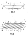
- FIG. 1 shows a bridge referenced 1 as a whole, with two spans, the unit length 1 of each span not exceeding 45 meters, the bridge being used for example for crossing motorway lanes 2 by a road secondary 3.
- the deck 1 comprises an apron 4 resting on a metal frame itself supported at its longitudinal ends by pillars or abutments 5a, 5b and in the middle by one or more pillars; only one pillar 6 has been shown in the figures, for the sake of clarity of the drawings.
- the foundations of the abutments 5a, 5b and of the pillar 6 have also not been shown for the sake of clarity of the drawing.
- the framework of the bridge rests on the abutments 5a and 5b and on the pillar 6 by means of jacks or support devices 7 constituting temporary supports allowing the compression of the bridge during manufacture, in a known manner and as will be explained below.
- FIG. 2 is a partial schematic top view of the bridge shown in Figure 1, by A the axis of the highway and R the axis of the secondary road. It is noted on examining FIG. 2 that the axes A and R do not intersect, in the particular embodiment described, at right angles, but at an angle.
- the deck 4 comprises a succession of slabs of slabs 8 in accordance with the invention and arranged side by side on two metal beams 9 of the framework of the bridge.
- the beams 9 extend parallel to the axis R of the secondary road and rest by their longitudinal ends on the abutments 5a and 5b, not shown in Figure 2 and oriented parallel to the axis A of the highway, the supports respective 10a and 10b of the beams 9 on the two abutments 5a and 5b being offset axially on the axis R. More specifically, the supports 10a and 10b are respectively arranged on each abutment 5a, 5b along a line L extending parallel to the axis A of the highway.
- the framework of the bridge also usually comprises spacers, not shown, extending between the two beams 9.
- the beams 9 conventionally have a cross section in the shape of 1, comprising horizontal lower and upper flanges connected by a vertical core.
- the slabs of slabs 8 have, seen from above, a shape in parallelogram, not rectangle in the case of the embodiment of FIG. 2, delimited by a front edge 11 and a rear edge 12 opposite, extending parallel to the axis A, and by opposite lateral faces 13, parallel to the axis R.
- the slabs 8 are arranged on the beams 9 front edge 11 against rear edge 12.
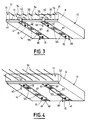
- the slab of slabs 8 has a lower face 14 or underside provided with screw jacks 15 capable of resting on the upper flange of the beams to provide a space allowing the introduction of a cement mortar between the slab of slabs and beams, as will be explained below.
- the slab of slabs 8 comprises two pairs of jacks arranged to bear respectively on each beam 9 so as to allow adjustment of the height and the inclination of the slab on the beams.
- the screw jacks 15 each consist of a nut housed in a through passage of the slab and of a threaded rod disposed in this passage, engaging the nut.
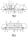
- a screw jack 15 There is shown more precisely in Figure 5 such a screw jack 15.
- 17 a through passage extending inside a sheath 17a, preferably vertically, that is to say perpendicular to the plane of the lower face 14
- reference 18 is a nut embedded in the concrete of the slab at the lower part of the passage 17
- reference 19 is a threaded rod engaged in the nut 18, provided at its lower end with a spherical head 21 resting on the surface 20a of the upper flange 20 of the beam 9.
- the nut 18 is fixed by its lower edge on a metal plate 22 arranged parallel to the plane of the lower face 14 of slab 8 and flush with the free surface thereof, and comprising sealing tabs embedded in the concrete of the slab.
- the plate 22 comprises two sealing lugs 23 symmetrically opposite with respect to the axis of the rod 19 and diverging in the concrete of the slab 8 away from the plate 22.
- the slab of slabs 8 in reinforced concrete includes reinforcements extending bare outside the front sections 11 and rear 12 in order to ensure, by covering the reinforcements between two successive slabs, the continuity of the longitudinal reinforcement (along the R axis) of the bridge deck 4.
- the front edge 11 has at its upper part a recess 30 opening onto the upper face of the slab, of generally parallelepiped shape, bordered laterally by two walls 31 and lowerly by an edge 40 constituting the lower edge of the slab, the edge 40 having a generally convex profile towards the outside and projecting in front of the side walls 31.
- the recess 30 delimits a volume in which two bare rows 34 and 35 of horizontal steel frames extend, oriented parallel to the side faces 13.
- the edge 40 which extends in front of the frames 34 and 35 is interrupted longitudinally in two places to form two notches 41 each located respectively above a beam 9 and serving for the connection of the reinforcements of the slab with vertical studs welded to the upper flange of the beam.
- the depth of the notches 41, measured along the longitudinal axis of the beams 9, is preferably equal to that of the recess 30.
- Inside the notches 41 lie bare horizontal reinforcements of the slab, some oriented parallel to the faces lateral 13 and the others parallel to the longitudinal direction of the slab, that is to say parallel to the front and rear edges.
- Stiffening ribs 42 extend laterally on either side of each of the notches 41 in the dihedral angle formed by the edge 40 and the bottom of the recess 30, in order to stiffen the edge 40 at the notches 41.
- the slab of slabs 8 has on its rear edge 12 two rows of horizontal frames 51 and 52 oriented parallel to the lateral faces 13.
- the rear edge 12 has at its lower edge a tucked edge 53 of profile generally complementary to that of the edge 40 so that the contiguous front 11 and rear 12 sections of two adjacent slabs constitute a formwork for the pouring of a concrete joint between these slabs, serving for the connection of the reinforcements of two adjacent slabs, without the need to add a formwork wall by in below, as will be explained below.
- each slab of slabs 8 comprises connection cells 55 opening onto the lower and upper faces of the slab and inside which extend the bare frames, these cells being arranged on the slab for come opposite the upper sole of the beams 9 with a view to connecting the reinforcements of the slab with the metal beams 9, by means of vertical studs welded to the upper sole of the beams 9.
- each slab of slabs 8 comprises two pairs of connection cells 55 arranged to come respectively opposite the two beams 9.
- the slab of slabs 8 is provided on its lower face 14 with vertical stops 60 arranged in order to laterally dock one at least of the two beams 9 and center the slab on them , during installation.
- the slab comprises two pairs of vertical stops 60, the two stops of the same pair being arranged to come into abutment respectively on the inner and outer lateral edges of the upper flange of the same beam 9.
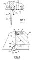
- FIG. 7 shows more precisely a vertical stop 60.
- This preferably consists, as shown, of a foot 60a of frustoconical shape, engaged at its base, in a removable manner and by means of a threaded rod, in a socket 60b embedded in the body of the slab.
- the slab 8 has horizontal docking stops capable of preventing impacts from the slabs of the slab.
- the slab 8 comprises two docking stops 70 protruding in front of the side walls 31 and in front of the frames 34, 35, along the longitudinal axis of the beams 9.
- FIG. 8 is a sectional view taken in a plane parallel to the side faces 13
- the docking stop 70 is constituted by a block of concrete molded on a threaded rod 71 retained in a socket 72 anchored in the body of the slab.
- the plane of the section of FIG. 8 contains the axis of the threaded rod 71.
- the edge 40 has three successive sides each inclined differently from the vertical, in particular a pan upper 40a directed towards the outside of the slab and downwards, a vertical intermediate panel 40b then a lower panel 40c directed towards the interior of the slab and towards the bottom.
- the tucked edge 53 also has three sides, including an upper section 53a parallel to the section 40a, an intermediate vertical section 53b, and a lower section 53c parallel to the section 53a.
- a gasket 59 known in itself is disposed between the upper panels 53a and 40a to seal between the edges 40 and 53 engaged one inside the other.
- abutments 5a and 5b and of the pillar 6 is carried out in a conventional manner, known to those skilled in the art, and therefore will not be described, as will the manufacture of slabs of slabs 8.
- the beams 9 are provided on their upper sole 20 and over their entire length, with seals 80 shown in cross section in Figures 5, 6 and 7.
- These seals 80 whose cross section recalls the shape of a note of music, have a tubular section part 80a extended tangentially and towards a median plane for the beam by a flattened tongue 81 fixed in a manner known per se (gluing for example) on the upper sole 20.
- the role of these joints 80 will be specified in the following.
- the beams provided with the joints 80 are placed, in a manner known per se, on temporary supports constituted by the jacks 7 provided on the abutments 5a, 5b and the pillar 6.
- the precast slabs 8, and provided with the rods cylinders 19 as well as vertical stops 60 are placed on the beams 9.
- the slabs comprise, on their upper face, lifting anchors known in themselves and not shown.
- the races of the screw jacks 15 are adjusted so as to provide between the upper surface of the sole 20 and the lower face 14 of the slab sufficient space for the introduction of a cement mortar, serving as a base for the slab of slabs 8 on the beams 9 and protecting the upper sole 20 of the beams from corrosion.
- the screw jacks 15, actuated in a manner known per se, also allow the inclination of each slab to be adjusted so as to obtain a continuous deck surface.
- Reinforcement rows 51 and 52 of a slab which appear respectively in line with the rows of reinforcements 34 and 35 of an adjacent slab in a recess 30 are welded together so as to ensure the continuity of the reinforcements along the bridge by overlapping the reinforcements.
- the reinforcements appearing naked in the connection cells 55 and in the notches 41 are connected to the upper flange 20 by means of vertical studs 95 welded to the beams.
- a cement mortar 90 (or of another material without shrinkage) into the space between the sole 20 and the lower surface 14 of the slab and laterally closed by the joints 80, as shown in FIGS. 5 and 6.
- the cement mortar 90 ensures the continuous seating of the precast concrete slabs on the beams 9.
- the slabs have, on their lower face grooves 97 whose bottom extends opposite the upper flange 20 of the beams, oriented parallel to the lateral faces 13 and extending longitudinally over the entire width of the slabs.
- the threaded rods 19 of the screw jacks are then advantageously recovered, as are the vertical stops 60 used for centering.
- the slabs are then bonded by pouring a concrete joint 100 between the slabs, in the recess 30, by means of the formwork produced by the interlocking of the edge 40 and the tucked edge 53, as well as the concreting of the cells of connection 55.
- the succession of slabs of slabs 8 is then put in compression edge to edge by actuation of the jacks 7 and unevenness of the temporary supports on the pillar 6, placing on final support on this pillar 6 then placing on final support of the bridge deck at the abutments 5a and 5b.
- a slab of slabs according to the invention makes it possible to reduce the duration of the bridge construction site, by facilitating the assembly of slabs of slabs on the framework and by eliminating in particular the operations of rectifying the centering of the slabs, of catching up of recess between the slabs, of setting up the formwork wall from below for the keying of the slabs.
Abstract
Description
La présente invention concerne une dalle de hourdis préfabriquée en béton armé utilisée pour la réalisation d'un tablier de pont supporté par une ossature métallique et plus particulièrement d'un tablier de pont à une ou plusieurs travées, la longueur unitaire de chaque travée n'excédant pas 45 mètres.The present invention relates to a precast reinforced concrete slab used for the production of a bridge deck supported by a metal frame and more particularly of a bridge deck with one or more spans, the unit length of each span n ' not exceeding 45 meters.
Des ponts à tablier supporté par une ossature métallique dont la longueur de travée unitaire est inférieure à 45 mètres sont utilisés par exemple pour la traversée d'une autoroute par une route secondaire, et comportent des piliers servant d'appui à deux poutres métalliques s'étendant côte à côte entre les piliers, pour supporter une succession de dalles formant le tablier du pont (voir, par exemple, FR-A-2 622 907).Apron bridges supported by a metal framework whose unit span length is less than 45 meters are used for example for the crossing of a highway by a secondary road, and include pillars serving as support for two metal beams s' extending side by side between the pillars, to support a succession of slabs forming the bridge deck (see, for example, FR-A-2 622 907).
Afin notamment de protéger de la corrosion la partie supérieure des poutres recevant les dalles, il est usuel de recouvrir la partie supérieure de celles-ci, avant la pose des dalles, d'un mortier de ciment servant par ailleurs d'assise aux dalles. Cependant, cette façon de procéder ne permet pas de corriger l'inclinaison des dalles posées sur ce mortier de ciment de sorte que la succession de dalles ne forme généralement pas une surface continue, mais présente des décrochements qu'il convient de rattraper ultérieurement par coulage sur les dalles d'une épaisse chape d'étanchéité en asphalte.In particular in order to protect the upper part of the beams receiving the slabs from corrosion, it is customary to cover the upper part of the latter, before laying the slabs, with a cement mortar which also serves as a base for the slabs. However, this way of proceeding does not make it possible to correct the inclination of the slabs laid on this cement mortar so that the succession of slabs does not generally form a continuous surface, but has notches which should be made up later by pouring. on the slabs of a thick asphalt waterproofing screed.
Un objet de l'invention est de proposer une dalle de hourdis préfabriquée perfectionnée ainsi qu'un procédé de réalisation d'un tablier de pont à partir de telles dalles, de façon à simplifier la construction du tablier d'un pont, et en diminuer le coût.An object of the invention is to provide an improved prefabricated slab of slabs as well as a method of producing a bridge deck from such slabs, so as to simplify the construction of a bridge deck, and to reduce it the cost.
Selon une première caractéristique de l'invention, la dalle comporte des passages traversants dans lesquels sont ancrés des écrous, en vue de recevoir des tiges filetées aptes à reposer par une extrémité sur les poutres pour constituer des vérins à vis permettant de ménager un espace suffisant entre la dalle et les poutres en vue d'y introduire un mortier de ciment servant d'assise aux dalles, après réglage de l'inclinaison de la dalle sur les poutres.According to a first characteristic of the invention, the slab has through passages in which nuts are anchored, in order to receive threaded rods capable of resting at one end on the beams to constitute screw jacks making it possible to provide sufficient space. between the slab and the beams in order to introduce a cement mortar serving as a foundation for the slabs, after adjusting the inclination of the slab on the beams.
On peut ainsi obtenir, grâce à l'invention, une surface continue de tablier de pont ne nécessitant pas de couler une épaisse chape d'étanchéité en asphalte. L'étanchéité peut alors être obtenue de façon moins coûteuse à l'aide de plaques en matériau synthétique, plus rapides à poser.It is thus possible, by virtue of the invention, to obtain a continuous surface of the bridge deck, which does not require a thick asphalt sealing screed to be poured. Sealing can then be obtained so less costly using synthetic material plates, faster to install.
Dans une réalisation préférée de l'invention, la dalle est réalisée par moulage d'un bloc en béton armé de forme générale parallélépipédique allongée, présentant des armatures s'étendant hors d'une tranche avant et d'une tranche arrière opposées de la dalle, l'une au moins des tranches avant et arrière de la dalle présentant un renfoncement ménageant un accès par le dessus aux armatures de deux dalles contiguës disposées tranche avant contre tranche arrière, en vue de leur connexion par coulage d'un joint de béton dans ledit renfoncement, les tranches avant et arrière présentant en deçà dudit renfoncement un bord en saillie et un bord rentré de formes généralement complémentaires de sorte que les tranches arrière et avant contiguës de deux dalles voisines constituent un coffrage pour le coulage du joint de béton dans ledit renfoncement, sans nécessiter de rapporter une paroi de coffrage par-dessous.In a preferred embodiment of the invention, the slab is produced by molding a reinforced concrete block of generally elongated parallelepiped shape, having reinforcements extending outside an opposite front edge and a rear edge of the slab , at least one of the front and rear sections of the slab having a recess providing access from above to the reinforcements of two contiguous slabs arranged front section against rear section, for their connection by pouring a concrete joint in said recess, the front and rear edges having below said recess a projecting edge and a tuck-in edge of generally complementary shapes so that the contiguous rear and front edges of two adjacent slabs constitute a formwork for pouring the concrete joint into said indentation, without the need to bring back a formwork wall from below.
Dans le cas où la ligne joignant les appuis des deux poutres sur un même pilier s'etend obliquement par rapport à l'axe longitudinal de celles-ci, ce qui est le cas lorsqu'une route secondaire franchit de biais une autoroute, l'emploi des seules dalles classiques connues, de forme rectangulaire, ne permet pas de couvrir les extrémités longitudinales des poutres. Il est alors connu selon l'art antérieur de réaliser un coffrage pour couler du béton et former des dalles d'extrémité sur mesure, ce qui accroît d'autant la durée et le coût du chantier.In the case where the line joining the supports of the two beams on the same pillar extends obliquely with respect to the longitudinal axis thereof, which is the case when a secondary road crosses a motorway at an angle, the use of the only known conventional slabs, of rectangular shape, does not make it possible to cover the longitudinal ends of the beams. It is then known according to the prior art to produce a formwork for pouring concrete and forming tailor-made end slabs, which increases the duration and the cost of the site accordingly.
Un autre objet de l'invention est de remédier à cet inconvénient en proposant des dalles permettant de couvrir les extrémités longitudinales des poutres. Dans une réalisation de l'invention, les dalles ont une forme de parallélépipède non rectangle telle que les tranches avant et arrière s'étendent parallèlement à ladite ligne joignant les appuis des deux poutres sur un même pilier.Another object of the invention is to remedy this drawback by proposing tiles making it possible to cover the longitudinal ends of the beams. In one embodiment of the invention, the slabs have a shape of a non-rectangular parallelepiped such that the front and rear edges extend parallel to said line joining the supports of the two beams on the same pillar.
Selon une caractéristique avantageuse de l'invention, la dalle comporte en sous-face des butées verticales pour accoster latéralement l'une au moins des deux poutres en vue du centrage de la dalle. De préférence, ces butées verticales sont reçues de façon amovible dans des douilles ancrées dans la dalle.According to an advantageous characteristic of the invention, the slab has vertical stops on the underside for laterally docking at least one of the two beams with a view to centering the slab. Preferably, these vertical stops are received removably in sockets anchored in the slab.
Selon une autre caractéristique avantageuse de l'invention, la dalle comporte sur l'une au moins de ses tranches avant et arrière deux butées d'accostage, disposées chacune au voisinage d'une face latérale de la dalle et en avant des armatures, propres à éviter les chocs des tranches de dalles.According to another advantageous characteristic of the invention, the slab comprises on at least one of its front and rear sections two docking stops, each arranged in the vicinity of a lateral face of the slab and in front of the reinforcements, proper to avoid impacts from slabs of slabs.
Selon une autre caractéristique avantageuse, la dalle comporte des alvéoles de connexion dans lesquelles s'étendent nues les armatures, agencées de façon à venir en regard des poutres lorsque les dalles sont posées sur celles-ci, deux de ces alvéoles débouchant en outre sur une tranche de la dalle en vue de disposer d'une surface de connexion suffisante avec les poutres sans fragilisation de la dalle.According to another advantageous characteristic, the slab comprises connection cells in which the reinforcements extend naked, arranged so as to come opposite the beams when the slabs are laid on them, two of these cells also opening onto a edge of the slab in order to have a sufficient connection surface with the beams without weakening the slab.
La présente invention a également pour objet un procédé de mise en oeuvre des dalles précitées pour réaliser un pont.The present invention also relates to a method of implementing the aforementioned slabs to make a bridge.
Selon une caractéristique du procédé selon l'invention, celui-ci comprend les étapes consistant à :
- . construire des piliers de support servant d'appui à deux poutres métalliques s'étendant côte à côte entre les piliers,
- . disposer les poutres sur lesdits piliers de support,
- . préfabriquer des dalles de hourdis conformes à l'invention,
- . disposer sur la longueur de chaque poutre, deux joints d'étanchéité espacés entre eux,
- . souder sur les poutres des goujons verticaux en vue de leur connexion avec les armatures des dalles de hourdis,
- . poser lesdites dalles de hourdis, équipées des tiges filetées et des butées verticales sur les deux poutres,
- . actionner les vérins à vis pour obtenir une surface continue de tablier de pont,
- . introduire un mortier de ciment servant d'assise aux dalles dans l'espace formé entre les dalles, les poutres et les joints d'étanchéité,
- . introduire un mortier de ciment dans les renfoncements formés entre les dalles en vue de la connexion des armatures des dalles adjacentes entre elles,
- . réaliser une chape d'étanchéité pour le tablier,
- . réaliser un revêtement servant de surface de roulement.
- . build support pillars serving as support for two metal beams extending side by side between the pillars,
- . placing the beams on said support pillars,
- . prefabricating slabs of slabs according to the invention,
- . place along the length of each beam, two gaskets spaced apart,
- . weld vertical studs to the beams in order to connect them to the reinforcement of the slabs of slabs,
- . lay said slabs of slabs, fitted with threaded rods and vertical stops on the two beams,
- . operate the screw jacks to obtain a continuous surface of the bridge deck,
- . introduce a cement mortar serving as a foundation for the slabs in the space formed between the slabs, the beams and the seals,
- . introduce a cement mortar into the recesses formed between the slabs in order to connect the reinforcements of the adjacent slabs to each other,
- . make a sealing cap for the deck,
- . make a coating serving as a rolling surface.
D'autres caractéristiques et avantages de la présente invention apparaîtront à la lecture de la description qui va suivre, d'un mode de réalisation non limitatif de l'invention, et à l'examen du dessin annexé sur lequel :
- la figure 1 est une vue en élévation latérale d'un pont permettant la traversée d'une autoroute par une route secondaire,
- la figure 2 est une vue de dessus schématique partielle du pont représenté sur la figure 1,
- les figures 3 et 4 sont des vues schématiques en perspective d'une dalle de hourdis conforme à l'invention, selon deux orientations opposées,
- la figure 5 est une vue en coupe schématique dans un plan contenant l'axe d'un vérin à vis et perpendiculaire à la direction longitudinale d'une poutre,
- la figure 6 est une vue en coupe schématique prise au niveau des alvéoles de connexion dans un plan perpendiculaire à la direction longitudinale d'une poutre,
- la figure 7 est une vue en coupe schématique prise dans un plan contenant l'axe d'une butée verticale de la dalle et perpendiculaire à la direction longitudinale d'une poutre,
- la figure 8 est une vue en coupe schématique prise dans un plan contenant l'axe d'une butée d'accostage de la dalle et parallèle à la direction longitudinale d'une poutre.
- FIG. 1 is a side elevation view of a bridge allowing the crossing of a highway by a secondary road,
- FIG. 2 is a partial schematic top view of the bridge shown in FIG. 1,
- FIGS. 3 and 4 are schematic perspective views of a slab of slabs according to the invention, in two opposite directions,
- FIG. 5 is a schematic sectional view in a plane containing the axis of a screw jack and perpendicular to the longitudinal direction of a beam,
- FIG. 6 is a schematic sectional view taken at the level of the connection cells in a plane perpendicular to the longitudinal direction of a beam,
- FIG. 7 is a schematic sectional view taken in a plane containing the axis of a vertical abutment of the slab and perpendicular to the longitudinal direction of a beam,
- Figure 8 is a schematic sectional view taken in a plane containing the axis of a docking stop of the slab and parallel to the longitudinal direction of a beam.
On a représenté sur la figure 1 un pont référencé 1 dans son ensemble, à deux travées, la longueur unitaire 1 de chaque travée n'excédant pas 45 mètres, le pont servant par exemple à la traversée de voies 2 d'autoroute par une route secondaire 3. Le pont 1 comprend un tablier 4 reposant sur une ossature métallique elle-même soutenue à ses extrémités longitudinales par des piliers ou culées 5a, 5b et en son milieu par un ou plusieurs piliers ; on n'a représenté sur les figures qu'un seul pilier 6, par souci de clarté des dessins. Les fondations des culées 5a, 5b et du pilier 6 n'ont également pas été représentées pour la clarté du dessin. De préférence, comme représenté sur la figure 1, l'ossature du pont repose sur les culées 5a et 5b et sur le pilier 6 par l'intermédiaire de vérins ou d'appareils d'appuis 7 constituant des appuis provisoires permettant la mise en compression du pont en cours de fabrication, de façon connue et comme cela sera précisé dans la suite.FIG. 1 shows a bridge referenced 1 as a whole, with two spans, the
On a référencé sur la figure 2, qui est une vue de dessus schématique partielle du pont représenté sur la figure 1, par A l'axe de l'autoroute et par R l'axe de la route secondaire. On remarque à l'examen de la figure 2 que les axes A et R ne se coupent pas, dans l'exemple de réalisation particulier décrit, à angle droit, mais de biais. Le tablier 4 comprend une succession de dalles de hourdis 8 conformes à l'invention et disposées côte à côte sur deux poutres métalliques 9 de l'ossature du pont. Les poutres 9 s'étendent parallèlement à l'axe R de la route secondaire et reposent par leurs extrémités longitudinales sur les culées 5a et 5b, non représentées sur la figure 2 et orientées parallèlement à l'axe A de l'autoroute, les appuis respectifs 10a et 10b des poutres 9 sur les deux culées 5a et 5b étant décalés axialement sur l'axe R. Plus précisément, les appuis 10a et 10b sont respectivement disposés sur chaque culée 5a, 5b selon une ligne L s'étendant parallèlement à l'axe A de l'autoroute. L'ossature du pont comporte également de manière usuelle des entretoises non représentées s'étendant entre les deux poutres 9. Les poutres 9 présentent classiquement une section transversale en forme de 1, comprenant des semelles inférieures et supérieures horizontales reliées par une âme verticale. Les dalles de hourdis 8 présentent, vues de dessus, une forme en parallélogramme, non rectangle dans le cas de l'exemple de réalisation de la figure 2, délimitée par une tranche avant 11 et une tranche arrière 12 opposées, s'étendant parallèlement à l'axe A, et par des faces latérales 13 opposées, parallèles à l'axe R. Les dalles 8 sont disposées sur les poutres 9 tranche avant 11 contre tranche arrière 12.We referenced in Figure 2, which is a partial schematic top view of the bridge shown in Figure 1, by A the axis of the highway and R the axis of the secondary road. It is noted on examining FIG. 2 that the axes A and R do not intersect, in the particular embodiment described, at right angles, but at an angle. The deck 4 comprises a succession of slabs of
On a représenté sur les figures 3 et 4, en perspective, de façon schématique et dans des orientations opposées, une dalle de hourdis 8 isolément. Selon l'invention, la dalle de hourdis 8 présente une face inférieure 14 ou sous-face munie de vérins à vis 15 aptes à reposer sur la semelle supérieure des poutres pour ménager un espace permettant l'introduction d'un mortier de ciment entre la dalle de hourdis et les poutres, comme cela sera précisé dans la suite. Plus précisément, la dalle de hourdis 8 comporte deux paires de vérins disposées pour s'appuyer respectivement sur chaque poutre 9 de façon à permettre un réglage de la hauteur et de l'inclinaison de la dalle sur les poutres.There is shown in Figures 3 and 4, in perspective, schematically and in opposite directions, a slab of
Selon une caractéristique de l'invention, les vérins à vis 15 sont constitués chacun par un écrou logé dans un passage traversant de la dalle et d'une tige filetée disposée dans ce passage, venant en prise avec l'écrou. On a représenté plus précisément sur la figure 5 un tel vérin à vis 15. On a référencé 17 un passage traversant, s'étendant à l'intérieur d'un fourreau 17a, de préférence verticalement, c'est-à-dire perpendiculairement au plan de la face inférieure 14, on a référencé 18 un écrou encastré dans le béton de la dalle à la partie inférieure du passage 17, et on a référencé 19 une tige filetée engagée dans l'écrou 18, munie à son extrémité inférieure d'une tête sphérique 21 reposant sur la surface 20a de la semelle supérieure 20 de la poutre 9. De préférence, comme représenté, l'écrou 18 est fixé par sa tranche inférieure sur une plaque métallique 22 disposée parallèlement au plan de la face inférieure 14 de la dalle 8 et à affleurement de la surface libre de celle-ci, et comprenant des pattes de scellement noyées dans le béton de la dalle. Plus précisément, la plaque 22 comprend deux pattes de scellement 23 symétriquement opposées par rapport à l'axe de la tige 19 et divergeant dans le béton de la dalle 8 en éloignement de la plaque 22.According to a characteristic of the invention, the screw jacks 15 each consist of a nut housed in a through passage of the slab and of a threaded rod disposed in this passage, engaging the nut. There is shown more precisely in Figure 5 such a
Si on se reporte de nouveau aux figures 3 et 4 on remarque que la dalle de hourdis 8, en béton armé, comprend des armatures s'étendant nues hors des tranches avant 11 et arrière 12 en vue d'assurer, par recouvrement des armatures entre deux dalles successives, la continuité du ferraillage longitudinal (selon l'axe R) du tablier 4 de pont. Plus particulièrement, dans l'exemple de réalisation décrit, la tranche avant 11 présente à sa partie supérieure un renfoncement 30 débouchant sur la face supérieure de la dalle, de forme généralement parallélépipédique, bordé latéralement par deux parois 31 et inférieurement par un bord 40 constituant l'arête inférieure de la dalle, le bord 40 présentant un profil généralement convexe vers l'extérieur et formant saillie en avant des parois latérales 31. Le renfoncement 30 délimite un volume dans lequel s'étendent nues deux rangées 34 et 35 d'armatures horizontales en acier, orientées parallèlement aux faces latérales 13. Le bord 40 qui s'étend en avant des armatures 34 et 35 est interrompu longitudinalement en deux endroits pour former deux entailles 41 situées chacune respectivement au-dessus d'une poutre 9 et servant à la connexion des armatures de la dalle avec des goujons verticaux soudés sur la semelle supérieure de la poutre. La profondeur des entailles 41, mesurée selon l'axe longitudinal des poutres 9, est de préférence égale à celle du renfoncement 30. A l'intérieur des entailles 41 s'étendent nues des armatures horizontales de la dalle, les unes orientées parallèlement aux faces latérales 13 et les autres parallèlement à la direction longitudinale de la dalle, c'est-à-dire parallèlement aux tranches avant et arrière. Des nervures de raidissement 42 s'étendent latéralement de part et d'autre de chacune des entailles 41 dans l'angle dièdre formé par le bord 40 et le fond du renfoncement 30, afin de rigidifier le bord 40 au niveau des entailles 41. La dalle de hourdis 8 présente sur sa tranche arrière 12 deux rangées d'armatures horizontales 51 et 52 orientées parallèlement aux faces latérales 13. La tranche arrière 12 présente à son arête inférieure un bord rentré 53 de profil généralement complémentaire de celui du bord 40 de sorte que les tranches avant 11 et arrière 12 contiguës de deux dalles voisines constituent un coffrage pour le coulage d'un joint de béton entre ces dalles, servant à la connexion des armatures de deux dalles adjacentes, sans nécessiter de rapporter une paroi de coffrage par en dessous, comme cela sera précisé dans la suite. On remarquera qu'en plus des entailles 41, la dalle 8 comporte des alvéoles de connexion 55 débouchant sur les faces inférieure et supérieure de la dalle et à l'intérieur desquelles s'étendent des armatures nues, ces alvéoles étant disposées sur la dalle pour venir en regard de la semelle supérieure des poutres 9 en vue de la connexion des armatures de la dalle avec les poutres métalliques 9, par l'intermédiaire de goujons verticaux soudés sur la semelle supérieure des poutres 9. Dans l'exemple de réalisation décrit sur les figures, chaque dalle de hourdis 8 comporte deux paires d'alvéoles de connexion 55 disposées pour venir respectivement en regard des deux poutres 9. On pourrait, sans sortir du cadre de l'invention, remplacer les entailles 41 par une partie en plein et disposer une alvéole de connexion supplémentaire située en retrait de la tranche avant 11. Cependant, la création d'une alvéole supplémentaire au centre de la dalle en diminuerait la solidité.If we refer again to Figures 3 and 4 we note that the slab of
Conformément à une autre caractéristique avantageuse de l'invention, la dalle de hourdis 8 est munie sur sa face inférieure 14 de butées verticales 60 disposées afin d'accoster latéralement l'une au moins des deux poutres 9 et centrer la dalle sur celles-ci, lors de la pose. De préférence, comme représenté, la dalle comporte deux paires de butées verticales 60, les deux butées d'une même paire étant disposées pour venir respectivement en butée sur les bords latéraux intérieur et extérieur de la semelle supérieure d'une même poutre 9. On a représenté plus précisément, figure 7, une butée verticale 60. Celle-ci est constituée de préférence, comme représenté, par un pied 60a de forme tronconique, engagé à sa base, de façon amovible et à la faveur d'une tige filetée, dans une douille 60b noyée dans le corps de la dalle.According to another advantageous characteristic of the invention, the slab of
Selon une autre caractéristique avantageuse de l'invention, la dalle 8 comporte des butées d'accostage horizontales propres à éviter les chocs des tranches de dalle. De préférence, comme représenté sur la figure 3, la dalle 8 comporte deux butées d'accostage 70 formant saillie en avant des parois latérales 31 et en avant des armatures 34, 35, selon l'axe longitudinal des poutres 9.According to another advantageous characteristic of the invention, the
Si l'on se reporte maintenant à la figure 8 qui est une vue en coupe prise dans un plan parallèle aux faces latérales 13, on remarque que, dans l'exemple de réalisation décrit, la butée d'accostage 70 est consituée par un bloc de béton moulé sur une tige filetée 71 retenue dans une douille 72 ancrée dans le corps de la dalle. Le plan de la coupe de la figure 8 contient l'axe de la tige filetée 71. On remarque également à l'examen de la figure 8 que le bord 40 présente trois pans successifs inclinés chacun différemment par rapport à la verticale, notamment un pan supérieur 40a dirigé vers l'extérieur de la dalle et vers le bas, un pan intermédiaire 40b vertical puis un pan inférieur 40c dirigé vers l'intérieur de la dalle et vers le bas. Le bord rentré 53 présente également trois pans, dont un pan supérieur 53a parallèle au pan 40a, un pan intermédiaire 53b vertical, et un pan inférieur 53c parallèle au pan 53a. Un joint 59 connu en lui-même est disposé entre les pans supérieurs 53a et 40a pour assurer l'étanchéité entre les bords 40 et 53 engagés l'un dans l'autre.If we now refer to Figure 8 which is a sectional view taken in a plane parallel to the side faces 13, we note that, in the embodiment described, the
La construction d'un tablier de pont à l'aide de dalles préfabriquées selon l'invention s'effectue de préférence de la manière qui va être décrite dans la suite.The construction of a bridge deck using prefabricated slabs according to the invention is preferably carried out in the manner which will be described below.
La construction des culées 5a et 5b et du pilier 6 s'effectue de façon classique, connue de l'homme de l'art, et par conséquent ne sera pas décrite, de même que la fabrication des dalles de hourdis 8. Les poutres 9 sont munies sur leur semelle supérieure 20 et sur toute leur longueur, de joints d'étanchéité 80 représentés en section transversale sur les figures 5, 6 et 7. Ces joints d'étanchéité 80, dont la section transversale rappelle la forme d'une note de musique, présentent une partie de section tubulaire 80a prolongée tangentiellement et vers un plan médian pour la poutre par une languette aplatie 81 fixée de façon connue en soi (collage par exemple) sur la semelle supérieure 20. Le rôle de ces joints 80 sera précisé dans la suite.The construction of
Les poutres munies des joints 80 sont posées, de façon connue en elles-mêmes, sur des appuis provisoires constitués par les vérins 7 prévus sur les culées 5a, 5b et le pilier 6. Les dalles de hourdis 8 préfabriquées, et munies des tiges de vérins 19 ainsi que des butées verticales 60 sont posées sur les poutres 9. Bien entendu, pour faciliter leur manutention, les dalles comportent, sur leur face supérieure, des ancres de levage connues en elles-mêmes et non représentées. Les courses des vérins à vis 15 sont ajustées de manière à ménager entre la surface supérieure de la semelle 20 et la face inférieure 14 de la dalle un espace suffisant pour l'introduction d'un mortier de ciment, servant d'assise à la dalle de hourdis 8 sur les poutres 9 et protégeant de la corrosion la semelle supérieure 20 des poutres. Les vérins à vis 15, actionnés de façon connue en elle-même, permettent également le réglage de l'inclinaison de chaque dalle de façon à obtenir une surface de tablier continue. Les rangées d'armatures 51 et 52 d'une dalle qui apparaissent respectivement au droit des rangées d'armatures 34 et 35 d'une dalle voisine dans un renfoncement 30 sont soudées entre elles de façon à assurer la continuité des armatures le long du pont par recouvrement des armatures. Les armatures apparaissant nues dans les alvéoles de connexion 55 et dans les entailles 41 sont connectées à la semelle supérieure 20 à la faveur de goujons verticaux 95 soudés sur les poutres. On procède alors à l'introduction, par gravité dans les alvéoles 55, d'un mortier de ciment 90 (ou d'un autre matériau sans retrait) dans l'espace compris entre la semelle 20 et la surface inférieure 14 de la dalle et fermé latéralement par les joints 80, comme représenté sur les figures 5 et 6. Le mortier de ciment 90 assure l'assise continue des dalles de hourdis préfabriquées sur les poutres 9. On notera, qu'afin de faciliter l'écoulement de ce mortier de ciment 90, les dalles présentent, sur leur face inférieure des rainures 97 dont le fond s'étend en regard de la semelle supérieure 20 des poutres, orientées parallèlement aux faces latérales 13 et s'étendant longitudinalement sur toute la largeur des dalles. Les tiges filetées 19 des vérins à vis sont ensuite avantageusement récupérées, de même que les butées verticales 60 servant au centrage. On procède ensuite au clavage des dalles par coulage d'un joint de béton 100 entre les dalles, dans le renfoncement 30, grâce au coffrage réalisé par l'emboîtement du bord 40 et du bord rentré 53, ainsi qu'au bétonnage des alvéoles de connexion 55. La succession de dalles de hourdis 8 est ensuite mise en compression tranche contre tranche par actionnement des vérins 7 et dénivellation des appuis provisoires sur le pilier 6, mise sur appui définitif sur ce pilier 6 puis mise sur appui définitif du tablier de pont au niveau des culées 5a et 5b. On procède ensuite à la réalisation de la chape d'étanchéité, avantageusement à l'aide de plaques en matière synthétique, puis on réalise un revêtement en asphalte servant de surface de roulement.The beams provided with the
Finalement, une dalle de hourdis selon l'invention permet de réduire la durée du chantier de construction du pont, en facilitant l'assemblage des dalles de hourdis sur l'ossature et en éliminant notamment les opérations de rectification du centrage des dalles, de rattrapage de décrochement entre les dalles, de mise en place de paroi de coffrage par en dessous pour le clavage des dalles.Finally, a slab of slabs according to the invention makes it possible to reduce the duration of the bridge construction site, by facilitating the assembly of slabs of slabs on the framework and by eliminating in particular the operations of rectifying the centering of the slabs, of catching up of recess between the slabs, of setting up the formwork wall from below for the keying of the slabs.
Claims (8)
- A prefabricated bridge slab (8) made of reinforced concrete for building the deck (4) of a bridge (1) of unit span length not exceeding 45 m, said bridge including pillars (5a, 5b, 6) serving as supports for two metal beams (9) extending side by side between the pillars to support a succession of said slabs, characterized in that the slab includes through passages (17) in which nuts (18) are anchored in order to receive threaded rods (19) suitable for resting at one end (21) on the beams to constitute screw jacks (15) enabling sufficient space to be provided between the slab and the beams for receiving cement mortar (90) on which the slabs are seated after adjusting slab inclination on the beams.
- A slab according to claim 1, characterized in that its bottom face (14) includes vertical abutment members (60) for laterally engaging at least one of the two beams (9) to center the slab.
- A slab according to claim 2, characterized in that the vertical abutment members (60) are constituted by legs (60a) removably received in sockets (60b) anchored in the slab.
- A slab according to any one of claims 1 to 3, characterized in that it is made by molding a block of reinforced concrete that is generally in the shape of an elongate parallelepiped, having reinforcing members (34, 35; 51, 52) extending beyond a front end face (11) and an opposite back end face (12) of the slab, at least one of the front and back end faces (11) of the slab having a setback (30) open to the top face of the slab and providing access from above to the reinforcing members of two contiguous slabs disposed front end face against back end face, in order to enable them to be connected together by casting a concrete joint in said setback, the front and back end faces presenting below said setback a projecting edge (40) and a setback edge (53) of generally complementary shape such that the contiguous front and back end faces of two adjacent slabs constitute shuttering for casting a concrete joint in said setback without it being necessary to apply a shuttering wall from beneath.
- A slab according to claim 4, characterized in that it is in the form of a non-rectangular parallelepiped such that the front and back end faces extend parallel to a line (L) interconnecting the seats (10a; l0b) of the two beams (9) on the same pillar (5a; 5b).
- A slab according to claim 4 or 5, characterized in that it includes on at least one (11) of its end faces, two engagement abutment members (70) each disposed in the vicinity of one of the side faces (13) of the slab and in front of the reinforcing bars (34, 35, 51, 52), and suitable for avoiding shocks between the end faces of the slabs.
- A slab according to any one of claims 4 to 6, characterized in that the slab includes connection recesses (41, 55) into which the reinforcing bars extend bare, disposed so as to overlie the beams (9) when the slabs are placed thereon, two of said recesses (41) also opening out into one of the end faces of the slab in order to provide sufficient connection area with the beams without making the slab fragile.
- A method of building a bridge (1) of span length not exceeding 45 m, the method comprising the operations consisting in:. building support pillars (5a, 5b, 6) serving as supports for two metal beams (9) extending side by side between the pillars;. placing the beams on said support pillars;. prefabricating bridge slabs (8) according to any one of claims 1 to 7;. placing two spaced-apart sealing gaskets (80) along the length of each beam;. welding vertical bolts (95) on the beams for connection with the reinforcement of the bridge slabs;. placing said bridge slabs fitted with threaded rods (19) and vertical abutment members (60) for centering on the two beams;. actuating the screw jacks (15) to obtain a continuous surface for the deck (4) of the bridge;. inserting cement mortar (90) to serve as seating for the slabs;. inserting cement mortar in the setbacks formed between the bridge slabs in order to connect together the reinforcement of mutually adjacent slabs;. making a sealing cover for the deck; and. making a covering serving as the running surface of the bridge.
Applications Claiming Priority (2)
| Application Number | Priority Date | Filing Date | Title |
|---|---|---|---|
| FR9215094 | 1992-12-15 | ||
| FR9215094A FR2699200B1 (en) | 1992-12-15 | 1992-12-15 | Prefabricated slab of concrete slabs and method of making a bridge using such slabs. |
Publications (2)
| Publication Number | Publication Date |
|---|---|
| EP0603060A1 EP0603060A1 (en) | 1994-06-22 |
| EP0603060B1 true EP0603060B1 (en) | 1996-11-06 |
Family
ID=9436607
Family Applications (1)
| Application Number | Title | Priority Date | Filing Date |
|---|---|---|---|
| EP93403021A Expired - Lifetime EP0603060B1 (en) | 1992-12-15 | 1993-12-14 | Prefabricated plate and method for making a bridge using such plates |
Country Status (5)
| Country | Link |
|---|---|
| EP (1) | EP0603060B1 (en) |
| AT (1) | ATE145027T1 (en) |
| DE (1) | DE69305831T2 (en) |
| ES (1) | ES2096893T3 (en) |
| FR (1) | FR2699200B1 (en) |
Families Citing this family (7)
| Publication number | Priority date | Publication date | Assignee | Title |
|---|---|---|---|---|
| DE102008007815A1 (en) * | 2008-02-05 | 2009-08-13 | Ssf Ingenieure Gmbh Beratende Ingenieure Im Bauwesen | Reinforced concrete composite bridge with horizontal joint and process for its production |
| US8316495B2 (en) | 2009-08-18 | 2012-11-27 | Yidong He | Method to compress prefabricated deck units with external tensioned structural elements |
| NL1037327C2 (en) * | 2009-09-28 | 2011-04-04 | Roland Angenent Holding B V | METHODS, COVER PLATE AND REINFORCED BRIDGE. |
| CN102733299B (en) * | 2012-07-13 | 2015-09-09 | 福州大学 | A kind of assembled steel reinforced concrete Supported Slab Bridge hinge seam and construction method thereof |
| EP2716817A1 (en) * | 2012-10-02 | 2014-04-09 | Airex AG | Adhesive connection for large composite components |
| CN111254830A (en) * | 2019-11-19 | 2020-06-09 | 中国铁建大桥工程局集团有限公司 | Rapid treatment method for bridge pier pull rod hole |
| CN114016415B (en) * | 2021-11-10 | 2024-02-06 | 宁波市高等级公路建设管理中心 | Large cantilever bent cap mounting structure based on UHPC permanent template |
Family Cites Families (3)
| Publication number | Priority date | Publication date | Assignee | Title |
|---|---|---|---|---|
| US1848582A (en) * | 1932-03-08 | Pavement | ||
| DE2520105A1 (en) * | 1975-05-06 | 1976-11-18 | Richard Dipl Ing Laumer | Composite construction interrupted reinforced concrete slab - has parts linked by girders with cutouts or latticed |
| FR2622907B1 (en) * | 1987-11-06 | 1991-06-28 | Pico Sogetrap Gestion Etu Trav | CIVIL ENGINEERING WORKS, ESPECIALLY BRIDGES AND CONSTRUCTION METHODS THEREOF |
-
1992
- 1992-12-15 FR FR9215094A patent/FR2699200B1/en not_active Expired - Fee Related
-
1993
- 1993-12-14 EP EP93403021A patent/EP0603060B1/en not_active Expired - Lifetime
- 1993-12-14 DE DE69305831T patent/DE69305831T2/en not_active Expired - Fee Related
- 1993-12-14 AT AT93403021T patent/ATE145027T1/en not_active IP Right Cessation
- 1993-12-14 ES ES93403021T patent/ES2096893T3/en not_active Expired - Lifetime
Also Published As
| Publication number | Publication date |
|---|---|
| ATE145027T1 (en) | 1996-11-15 |
| ES2096893T3 (en) | 1997-03-16 |
| EP0603060A1 (en) | 1994-06-22 |
| FR2699200A1 (en) | 1994-06-17 |
| DE69305831D1 (en) | 1996-12-12 |
| FR2699200B1 (en) | 1995-03-03 |
| DE69305831T2 (en) | 1997-05-15 |
Similar Documents
| Publication | Publication Date | Title |
|---|---|---|
| EP0295175B2 (en) | Hollow structure with flat base plate | |
| CA1232466A (en) | Glass component, especially glass brick or paving block | |
| EP0603060B1 (en) | Prefabricated plate and method for making a bridge using such plates | |
| EP0244890B1 (en) | Process for producing hollow structures such as ducts, silos, or shelters, and structures obtained by this process | |
| EP0585959B1 (en) | Entrenched conduit | |
| FR2903437A1 (en) | Prefabricated element for forming e.g. reinforced concrete wall e.g. bridge pillar, has metallic beam extending along longitudinal direction and comprising lower head beam drowned in plate extending between two spaced lateral sides | |
| FR2620153A1 (en) | CONSTRUCTION PANEL, ESPECIALLY CLADDING PANEL, WITH INTEGRATED THERMAL INSULATION | |
| JPH07252870A (en) | Rain water storage tank | |
| FR2642109A1 (en) | Elongate hollow structure and method for manufacturing it | |
| BE1001360A3 (en) | Deck semi-prefabricated. | |
| FR2578904A1 (en) | PROCESS FOR THE PRODUCTION OF A TUNNEL | |
| EP0500444A1 (en) | Underground tubular structure | |
| FR3013062A1 (en) | ARMED CONCRETE SUPPORT STRUCTURE FOR RAILWAY AND METHOD OF OBTAINING | |
| EP2231947B1 (en) | Prefabricated element for creating a reinforced concrete slab and slab thus created | |
| JP7178050B2 (en) | Pile support structure and its construction method | |
| FR2727447A1 (en) | Construction of tunnel under embankment in soft soils or areas prone to flooding | |
| EP1258565A1 (en) | Prefabricated bridge bearing | |
| EP0242497A1 (en) | Tunnel construction process | |
| FR2938858A1 (en) | Concrete floor framework for e.g. buried parking area, in building site, has posts surmounted by capital presenting variable inertia section maximal at right of posts, and beams whose ends are set with respect to each other in posts axis | |
| FR2878877A1 (en) | Formwork block for e.g. manufacturing lintel, has vertical walls with flanges exceeding horizontal wall to form U-shape of height greater than beam, where inner sides of flanges have abutments separated at distance equal to beam`s thickness | |
| EP0004998A2 (en) | Construction frame | |
| FR2738580A1 (en) | Composite cast and prefabricated bridge deck construction | |
| FR2812323A1 (en) | Prefabricated concrete swimming pool is composed of two longitudinal elements forming vertical wall and bottom wall portion having longitudinal rabbet fitting rabbet in bottom slab forming pool bottom and two end elements | |
| EP2821552A1 (en) | Gateway and method for producing such a gateway | |
| FR2833290A1 (en) | Low wall constructed from prefabricated components has at least one U-section panel with end apertures for connecting to foundation blocks |
Legal Events
| Date | Code | Title | Description |
|---|---|---|---|
| PUAI | Public reference made under article 153(3) epc to a published international application that has entered the european phase |
Free format text: ORIGINAL CODE: 0009012 |
|
| AK | Designated contracting states |
Kind code of ref document: A1 Designated state(s): AT BE CH DE ES FR GB IE IT LI LU NL PT |
|
| 17P | Request for examination filed |
Effective date: 19941024 |
|
| GRAG | Despatch of communication of intention to grant |
Free format text: ORIGINAL CODE: EPIDOS AGRA |
|
| 17Q | First examination report despatched |
Effective date: 19951215 |
|
| GRAH | Despatch of communication of intention to grant a patent |
Free format text: ORIGINAL CODE: EPIDOS IGRA |
|
| GRAH | Despatch of communication of intention to grant a patent |
Free format text: ORIGINAL CODE: EPIDOS IGRA |
|
| GRAH | Despatch of communication of intention to grant a patent |
Free format text: ORIGINAL CODE: EPIDOS IGRA |
|
| GRAH | Despatch of communication of intention to grant a patent |
Free format text: ORIGINAL CODE: EPIDOS IGRA |
|
| GRAA | (expected) grant |
Free format text: ORIGINAL CODE: 0009210 |
|
| AK | Designated contracting states |
Kind code of ref document: B1 Designated state(s): AT BE CH DE ES FR GB IE IT LI LU NL PT |
|
| REF | Corresponds to: |
Ref document number: 145027 Country of ref document: AT Date of ref document: 19961115 Kind code of ref document: T |
|
| REG | Reference to a national code |
Ref country code: IE Ref legal event code: FG4D Free format text: 70550 |
|
| REF | Corresponds to: |
Ref document number: 69305831 Country of ref document: DE Date of ref document: 19961212 |
|
| ITF | It: translation for a ep patent filed |
Owner name: CON LOR S.R.L. |
|
| GBT | Gb: translation of ep patent filed (gb section 77(6)(a)/1977) |
Effective date: 19970207 |
|
| REG | Reference to a national code |
Ref country code: CH Ref legal event code: NV Representative=s name: BOVARD AG PATENTANWAELTE |
|
| REG | Reference to a national code |
Ref country code: ES Ref legal event code: FG2A Ref document number: 2096893 Country of ref document: ES Kind code of ref document: T3 |
|
| PLBE | No opposition filed within time limit |
Free format text: ORIGINAL CODE: 0009261 |
|
| STAA | Information on the status of an ep patent application or granted ep patent |
Free format text: STATUS: NO OPPOSITION FILED WITHIN TIME LIMIT |
|
| 26N | No opposition filed | ||
| REG | Reference to a national code |
Ref country code: GB Ref legal event code: IF02 |
|
| PGFP | Annual fee paid to national office [announced via postgrant information from national office to epo] |
Ref country code: AT Payment date: 20041119 Year of fee payment: 12 |
|
| PGFP | Annual fee paid to national office [announced via postgrant information from national office to epo] |
Ref country code: IE Payment date: 20041123 Year of fee payment: 12 |
|
| PGFP | Annual fee paid to national office [announced via postgrant information from national office to epo] |
Ref country code: GB Payment date: 20041130 Year of fee payment: 12 |
|
| PGFP | Annual fee paid to national office [announced via postgrant information from national office to epo] |
Ref country code: PT Payment date: 20041206 Year of fee payment: 12 Ref country code: DE Payment date: 20041206 Year of fee payment: 12 |
|
| PGFP | Annual fee paid to national office [announced via postgrant information from national office to epo] |
Ref country code: CH Payment date: 20041210 Year of fee payment: 12 |
|
| PGFP | Annual fee paid to national office [announced via postgrant information from national office to epo] |
Ref country code: ES Payment date: 20041213 Year of fee payment: 12 |
|
| PG25 | Lapsed in a contracting state [announced via postgrant information from national office to epo] |
Ref country code: IT Free format text: LAPSE BECAUSE OF NON-PAYMENT OF DUE FEES;WARNING: LAPSES OF ITALIAN PATENTS WITH EFFECTIVE DATE BEFORE 2007 MAY HAVE OCCURRED AT ANY TIME BEFORE 2007. THE CORRECT EFFECTIVE DATE MAY BE DIFFERENT FROM THE ONE RECORDED. Effective date: 20051214 Ref country code: IE Free format text: LAPSE BECAUSE OF NON-PAYMENT OF DUE FEES Effective date: 20051214 Ref country code: GB Free format text: LAPSE BECAUSE OF NON-PAYMENT OF DUE FEES Effective date: 20051214 Ref country code: AT Free format text: LAPSE BECAUSE OF NON-PAYMENT OF DUE FEES Effective date: 20051214 |
|
| PG25 | Lapsed in a contracting state [announced via postgrant information from national office to epo] |
Ref country code: ES Free format text: LAPSE BECAUSE OF NON-PAYMENT OF DUE FEES Effective date: 20051215 |
|
| PG25 | Lapsed in a contracting state [announced via postgrant information from national office to epo] |
Ref country code: LI Free format text: LAPSE BECAUSE OF NON-PAYMENT OF DUE FEES Effective date: 20051231 Ref country code: CH Free format text: LAPSE BECAUSE OF NON-PAYMENT OF DUE FEES Effective date: 20051231 |
|
| PG25 | Lapsed in a contracting state [announced via postgrant information from national office to epo] |
Ref country code: PT Free format text: LAPSE BECAUSE OF NON-PAYMENT OF DUE FEES Effective date: 20060614 |
|
| PG25 | Lapsed in a contracting state [announced via postgrant information from national office to epo] |
Ref country code: DE Free format text: LAPSE BECAUSE OF NON-PAYMENT OF DUE FEES Effective date: 20060701 |
|
| REG | Reference to a national code |
Ref country code: CH Ref legal event code: PL |
|
| GBPC | Gb: european patent ceased through non-payment of renewal fee |
Effective date: 20051214 |
|
| REG | Reference to a national code |
Ref country code: PT Ref legal event code: MM4A Effective date: 20060614 |
|
| REG | Reference to a national code |
Ref country code: IE Ref legal event code: MM4A |
|
| REG | Reference to a national code |
Ref country code: FR Ref legal event code: CJ |
|
| REG | Reference to a national code |
Ref country code: ES Ref legal event code: FD2A Effective date: 20051215 |
|
| PGFP | Annual fee paid to national office [announced via postgrant information from national office to epo] |
Ref country code: NL Payment date: 20081118 Year of fee payment: 16 |
|
| REG | Reference to a national code |
Ref country code: NL Ref legal event code: V1 Effective date: 20100701 |
|
| PG25 | Lapsed in a contracting state [announced via postgrant information from national office to epo] |
Ref country code: NL Free format text: LAPSE BECAUSE OF NON-PAYMENT OF DUE FEES Effective date: 20100701 |
|
| PGFP | Annual fee paid to national office [announced via postgrant information from national office to epo] |
Ref country code: LU Payment date: 20101123 Year of fee payment: 18 |
|
| PGFP | Annual fee paid to national office [announced via postgrant information from national office to epo] |
Ref country code: BE Payment date: 20110117 Year of fee payment: 18 |
|
| PGFP | Annual fee paid to national office [announced via postgrant information from national office to epo] |
Ref country code: FR Payment date: 20120105 Year of fee payment: 19 |
|
| BERE | Be: lapsed |
Owner name: *NORPAC Effective date: 20111231 Owner name: *DEMATHIEU ET BARD Effective date: 20111231 Owner name: SOC. DES *AUTOROUTES DU NORD ET DE L'EST DE LA FRA Effective date: 20111231 Owner name: SOC. CENTRALE D'*ETUDES ET DE *REALISATIONS ROUTIE Effective date: 20111231 |
|
| PG25 | Lapsed in a contracting state [announced via postgrant information from national office to epo] |
Ref country code: BE Free format text: LAPSE BECAUSE OF NON-PAYMENT OF DUE FEES Effective date: 20111231 |
|
| PG25 | Lapsed in a contracting state [announced via postgrant information from national office to epo] |
Ref country code: LU Free format text: LAPSE BECAUSE OF NON-PAYMENT OF DUE FEES Effective date: 20111214 |
|
| REG | Reference to a national code |
Ref country code: FR Ref legal event code: ST Effective date: 20130830 |
|
| PG25 | Lapsed in a contracting state [announced via postgrant information from national office to epo] |
Ref country code: FR Free format text: LAPSE BECAUSE OF NON-PAYMENT OF DUE FEES Effective date: 20130102 |