EP0242497A1 - Tunnel construction process - Google Patents
Tunnel construction process Download PDFInfo
- Publication number
- EP0242497A1 EP0242497A1 EP86870058A EP86870058A EP0242497A1 EP 0242497 A1 EP0242497 A1 EP 0242497A1 EP 86870058 A EP86870058 A EP 86870058A EP 86870058 A EP86870058 A EP 86870058A EP 0242497 A1 EP0242497 A1 EP 0242497A1
- Authority
- EP
- European Patent Office
- Prior art keywords
- tunnel
- elements
- vertical
- successive
- vertical elements
- Prior art date
- Legal status (The legal status is an assumption and is not a legal conclusion. Google has not performed a legal analysis and makes no representation as to the accuracy of the status listed.)
- Granted
Links
Images


Classifications
-
- E—FIXED CONSTRUCTIONS
- E02—HYDRAULIC ENGINEERING; FOUNDATIONS; SOIL SHIFTING
- E02D—FOUNDATIONS; EXCAVATIONS; EMBANKMENTS; UNDERGROUND OR UNDERWATER STRUCTURES
- E02D29/00—Independent underground or underwater structures; Retaining walls
- E02D29/045—Underground structures, e.g. tunnels or galleries, built in the open air or by methods involving disturbance of the ground surface all along the location line; Methods of making them
- E02D29/05—Underground structures, e.g. tunnels or galleries, built in the open air or by methods involving disturbance of the ground surface all along the location line; Methods of making them at least part of the cross-section being constructed in an open excavation or from the ground surface, e.g. assembled in a trench
-
- E—FIXED CONSTRUCTIONS
- E02—HYDRAULIC ENGINEERING; FOUNDATIONS; SOIL SHIFTING
- E02D—FOUNDATIONS; EXCAVATIONS; EMBANKMENTS; UNDERGROUND OR UNDERWATER STRUCTURES
- E02D29/00—Independent underground or underwater structures; Retaining walls
- E02D29/045—Underground structures, e.g. tunnels or galleries, built in the open air or by methods involving disturbance of the ground surface all along the location line; Methods of making them
Definitions
- the present invention relates to a method for constructing tunnels by means of prefabricated concrete elements, joined together on site by concreting.
- tunnels are generally done by construction of successive sections.
- the most common processes currently in this area are: - the open excavation process, in which an reinforced concrete frame composed of a raft, vertical sails and upper slabs is produced in an open trench, and - the armored excavation process, according to which a lateral shielding of the excavation is carried out before making a reinforced concrete frame as above.
- the sails of the tunnel section can also be produced using the lateral armor of the excavation, or by mud walls which serve as armor for the ground.
- the tunnels are produced either by pouring successive tunnel sections in place, or by aligning prefabricated tunnel sections.
- the tunneling process which consists of aligning prefabricated tunnel sections allows the length of the site to be reduced.
- the prefabricated sections are placed, the backfilling and finishing work can be carried out.
- the object of the present invention is a method for the construction of tunnels, by assembling prefabricated elements which: - only requires a short site, - accommodates narrow work sites, - uses common site machinery, self-propelled, which is a low nuisance, - allows rapid movement of the site along the axis of the tunnel, thanks to the repetition of a series of simple operations, - limits the displacements of ground prejudicial to the constructions adjacent to the building site, - requires a reduced earthwork front, which makes it possible to build tunnels even within other construction sites, - does not disturb the ground level, the volume of evacuated soil practically corresponding to the volume of the tunnel.
- the process according to the present invention in fact calls upon a certain number of preferred elements.
- standardized briquettes of relatively reduced weight (around 10 tonnes), the handling of which requires only more mobile lifting equipment, of the type commonly used on most construction sites.
- These lifting devices can be automobile cranes, which do not need to be mounted on rails.
- the use of standardized prefabricated elements makes it possible for the process of the invention to make tunnels of small section and tunnels of larger section, for example for large gauge metro, underground railway, etc., by juxtaposing a greater or lesser number of these standardized elements.
- the method according to the invention makes it possible to vary the section of the tunnels, which can thus pass from a minimum section (for a single tunnel section of line) to a maximum section (sections of tunnel comprising stations, with landing platforms, waiting rooms, etc.) passing through intermediate sections. It is even possible to produce, according to the method of the invention, two-level tunnels.
- the present invention relates to a method for the construction of a tunnel by means of prefabricated concrete elements, which are joined together by concreting, after placement.
- the construction of a tunnel comprises the following phases: - excavation, directly above the vertical walls of the tunnel in progress, of armored excavations of dimensions slightly greater than those of prefabricated reinforced concrete elements intended to partially constitute the walls of the tunnel, - realization of a foundation foundation, - introduction, positioning and alignment of vertical elements in their excavation, each element, spaced from the previous one, being arranged in line with a similar element placed on the other side of the tunnel, - backfilling of excavations with stabilized backfill material and simultaneous removal of shields, - frontal pre-embankment of the volume of the tunnel gradually clearing the top of the vertical elements of a section of tunnel, - Installation of lintels parallel to the axis of the tunnel, so that each lintel is supported by its ends at the upper part of two successive vertical elements; - laying of transverse upper beams, each beam resting at its ends on lintels arranged opposite one another on either side of the tunnel, - frontal digging of the volume of the tunnel gradually releasing each pair of
- the successive phases of realization of the tunnel are executed in order along the construction site, from the installation of the vertical elements to the zone of completion where the backfilling and the covering take place. of the completed tunnel.
- the installation of two contiguous elements is separated by a time interval ensuring the stabilization of the fill material.
- a section of site extends over the length corresponding to the installation of six successive vertical elements.
- the vertical elements partially constituting the side walls of the tunnel are oblong shells of reinforced concrete having a cylindrical arch whose generator is parallel to the major axis of the shells; these shells are closed at each of their ends by a base, perpendicular to their major axis.
- These shells are arranged in such a way that their concave side is directed towards the interior of the tunnel, and that their arch is directed towards the walls of the trench.
- a vertical element is advantageously extended, at its lower part, by a heel which remains stuck in the ground during the excavation of the volume of the tunnel, so as to maintain the element in place before the installation of a beam shoring.
- the shells have two flat and parallel side panels extending the arch on each side thereof.
- the lateral faces of a shell have, on the side of the interior of the tunnel, a rebate intended for the installation of formwork plates and cells intended for the introduction of pins for the maintenance of these plates.
- the shells have on the outer faces of the side panels, near their edge directed towards the outside of the tunnel, a groove parallel to the long axis of the shells, capable of receiving the lateral edge of a plate formwork.
- the rear face of a shell is extended upwards by a shoulder forming shuttering during concreting of the upper slab of the tunnel.
- the face of a shell turned towards the outside of the tunnel is substantially planar and is connected perpendicularly to its lateral faces.
- the shells have vertical grooves on the lateral external faces which improve their connection with the elements of the tunnel cast on site.
- the shell is provided, in its lower part, with openings, the axis of which is parallel to the axis of the tunnel, which are intended for the passage of concrete reinforcing pieces intended to be embedded in concrete during pouring.
- the edge of the side panels of the shells has at its upper part, a recess intended to support the end of a lintel held in place by bolting.
- the concave face of the shells is closed during their installation.
- the shells are closed by a cover made of a steel sheet.
- the assembly of a beam, of the two reinforced concrete columns which support each of the ends of this beam and the raft supporting each of these reinforced concrete columns, forms a framework capable of taking up the vertical pressures exerted by the land and the road network higher, as well as the horizontal earth pressure.
- the method according to the invention has a number of advantages.
- the arched shape of the hulls preferably used offers the advantage of taking up the horizontal loads of pushing the earth with relatively thin partitions and not requiring additional reinforcements.
- the number of prefabricated elements used being reduced (in fact, it mainly comprises only shoring beams, the vertical elements forming the vertical walls, lintels, upper beams and the slabs), the installation of these elements is a following repeated operations, which promotes speed of execution.
- the spreading phases of a tunnel section are broken down as follows: from 1st to 4th day: prior placement in the floor of vertical elements (shells), from the 5th to the 10th day: clearing of the hull heads, installation of lintels and transverse beams, excavation, installation of shoring beams, concreting of the columns, from the 10th to the 17th day: setting of the concrete, 18th to 19th day: fitting the waterproofing cover, from the 20th to the 24th day: drying of the seal, 25th day: backfill.
- the method also makes it possible to spread the working times over successive sections at different stages of completion in such a way that the progression of the tunnel continues continuously, with no downtime for the workforce, even during the lapse of time required for hardening of the concrete or during drying of the products applied for the waterproofing cover.
- the process provides for a first phase of placing vertical elements in the ground, a phase which can progress at its own pace ahead of the site itself, which allows a large spread of tasks depending on time constraints.
- the site installations themselves also occupy a reduced floor area due to the mobility of the site and the use of a maximum of prefabricated elements off site.
- the process also allows to marry the various unevenness of the terrain as well as the changes of direction imposed by the layout, while using the majority of the prefabricated elements above.
- the method also lends itself to the construction of tunnels of various widths; one can for example, make narrow passages for straight sections, or wider sections for stations, or even intermediate sections connecting the narrow sections and the wide sections. As will be described later, these different widths are produced without problem with the prefabricated elements already described.
- the process according to the invention makes it possible to combine the structural work and the finishing touches; in particular inside the stations one can take advantage of the shape of the hulls.
- the dimensions of these shells can vary between relatively wide limits, but according to a particular and advantageous embodiment of the invention, the width of these shells is between 2 and 3 meters.
- the walls of the stations are presented as a succession of niches, which can be arranged as required.
- the benches can advantageously be ribs of any shape forming one body with the shells, produced during the factory manufacture of these.
- the shells forming the walls of the tunnel between the stations can be arranged to receive electrical devices such as junction boxes, lighting, signaling devices, etc.
- the particular configuration of the walls can also be used advantageously acoustically. Indeed, sounds are picked up by the surface of the walls, which considerably lowers the acoustic level and thus improves the comfort of tunnel users, especially passengers waiting at stations.
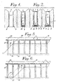
- Figs. 1 and 2 show two cross-sectional views of the tunnel during the prior positioning of the vertical elements 1.
- a dig 2 On either side of the tunnel, at the base of the space provided for the vertical walls, a dig 2 has been dug so large that it is possible to introduce a vertical element in the form of a shell 1 of reinforced concrete intended to constitute a part of the side walls.
- This excavation 2 can be carried out in any way, but it is advantageously possible to use a rapid digging method where the excavation is propped up by interlocking metallic shields 3 slid in place as the digging progresses.
- a seat 4 is produced which is intended to facilitate the positioning of the shell 1 which is placed vertically in the excavation 2.
- a closure means 7 such as a sheet of suitable shape.
- Fig. 2 shows in cross section two final stages of the prior placement of the shells 1.
- the shield 3 is progressively reassembled, while introducing into the remaining space between the shell 1 and the sides of the excavation 8, a backfill material 9 such as, for example, stabilized slag or stabilized sand.
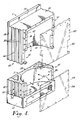
- Fig. 4 shows a perspective view, with cutaway, of a particular shape of a vertical shell-shaped element 1 used in the construction method according to the invention.
- This element has a cylindrical arch 10 whose generator is parallel to the axis of the shell. It is enclosed at each of its ends by a base 11 perpendicular to its major axis.
- Two side panels 12 extend the vault 10 on each side thereof.
- the rear face 13 of the shell 1 is practically flat and is connected perpendicularly to the side faces 14.
- Such a shape contributes to reducing the manufacturing costs of these elements which can be prefabricated in molds of standard shape.
- the edge of the side panels 12 comprises, near the top of the element, a recess 15 intended to support the end of a lintel fixed by bolting, as will be seen in FIG. 5.
- the lateral faces 14 of the shell 1 compor tent on the side facing the inside of the tunnel, a rebate 16 extending over the entire height of the element, as well as perforations 17 allowing the insertion of pins intended to hold shuttering panels in the rebates 16, as will be described later.
- the side faces 14 of the shell 1 have, on the side facing the outside of the tunnel, a groove 18 which extends over the entire height of the shell 1.
- This groove 18 makes it possible to insert a rear formwork panel over any or part of the height of the hull 1.
- This formwork panel cooperates, at the time of concreting, with the shoulder 19 which extends like a crest the rear face 13 of the shell 1.
- the lateral faces 14 of the shell 1 have vertical grooves 20 intended to improve the connection of the shell 1 with the adjacent reinforced concrete elements.
- the shell 1 is pierced with openings 21 which pass through the side panels 12 right through.
- the foot of the shell 1 is extended by a heel 22 whose function is described below.
- a closure means 7 consisting of a plate 23 provided with stiffeners 24 is fixed, in this case by bolts, in front of the concave face 6 of the shell so as to close it during its installation.
- This plate 23 is cut so that the lintels can be put in place without having to remove it.
- Fig. 3 shows an advantageous sequence for the installation of the shells.
- FIG. 3 The sequence described in FIG. 3 is designed in such a way that it avoids the successive laying of two contiguous elements, both to avoid ground movements and to allow the stabilization of the fill material 9.
- a judicious distribution of the work, as shown in FIG . 3, allows the twelve hulls 1 corresponding to a section of the site to be installed without problems in four days.
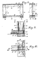
- Figs. 5 and 6 show in a sectional view along a vertical plane parallel to the axis of the tunnel, two successive stages of excavation of a tunnel produced according to the invention.
- Fig. 5 shows the tunnel after pre-excavation of a first layer of soil 25 freeing the head of the shells 1 from a section.
- the slope of the earthwork front 26 is gentle so that the base of the hulls 1 not yet secured is held in place despite the lateral thrust of the earth.
- Fig. 6 shows the progression of the earthwork front 26 and the simultaneous joining of the hulls 1.
- a lintel 27 is fixed in place between two successive shells 1; these lintels 27 support a transverse beam 28 which connects between them two lintels 27 facing each other on either side of the tunnel.
- the earthwork front 26 thus successively releases each pair of shells 1 over their entire height.
- the lateral thrust exerted by the earth is temporarily compensated by the heel 22 which remains buried in the ground.
- the dimensions of this heel 22 are determined from the mechanical characteristics of the ground.
- the shoring beam 29 is placed there, which then takes up the thrust exerted on the lateral faces of the tunnel.
- the interval 30 separating two successive shells 1 is released from the backfill material 9.
- a reinforcement 31 is introduced therein cooperating with longitudinal reinforcement elements 32 joining the bottom of the shells 1 in the same row.
- the interval 30 between two successive shells 1 is then closed by a formwork plate 33 applied in the rebates 16.
- the transverse upper beams 28 support pre-slabs 37 in reinforced concrete, arranged in such a way that each pre-slab 37 is supported by its front edge on a transverse upper beam 28, and by its rear edge on the following transverse upper beam 28.
- Transverse beams 28 and slabs 27 form, by the way they adjust, a formwork for pouring the upper slab 38.
- the lateral faces of this formwork are constituted by the shoulder 19 which extends upwards the rear face 13 hulls as well as by panels of formwork 39 inserted in the grooves 18 formed near the rear edge of the side faces 14 of these elements.
- the tunnel progress continues without interruption by a simple task transfer to the other sections at various stages of completion.
- the upper part of the tunnel is coated with a sealing layer and backfilling is carried out.
- Fig. 8 is a section through the tunnel, perpendicular to its axis, indicating the three successive concreting phases necessary to produce a gantry capable of taking up the lateral and vertical thrusts exerted by the earth on the tunnel.
- Phase 1 concerns the raft 35 and the double longitudinal sole 36 which extends over the entire length of the tunnel.
- Phase 2 concerns the vertical columns 34 located between the shells 1.
- Phase 3 concerns the joining of these vertical columns 34, the transverse beams 28 and the upper slab 38 of the structure.
- Figs. 9 and 10 show two sections, one in elevation, the other in plan, of the base of a column 34 joining two shells 1. This location constitutes a real knot in the structure of the tunnel since reinforcements join there. taking up stresses coming from three different directions, namely the reinforcements 31 of the vertical column 34, not shown, located between two shells 1, the reinforcement 32, the longitudinal "beam” 36 which connects all the shells of a row and the prop beam tement 29 and strike off 35 which transversely connects the two sides of the tunnel.
- the method according to the invention has the advantage of allowing the tunnel to follow the various unevennesses of the terrain as well as the height changes imposed by the layout.
- FIG. 11 and 12 An example of such a tunnel is illustrated in Figs. 11 and 12, in which the elements common to all the embodiments described have the same reference numbers.
- Figs. 11 and 12 illustrate a straight-aligned tunnel whose slope is sloping.
- the different production phases are the same as those described above for the construction of a straight and horizontal tunnel.
- the successive hulls are placed at different levels depending on the slope of the tunnel to be built.
- the shells are placed vertically since it is essential that the columns which will be cast in the spaces between the successive shells are vertical.
- a lintel of this type as illustrated in FIG. 12, has at its upper surface two bearing surfaces 40 and 41 offset, separated by a rung 42 whose height is equal to the difference in level between two successive shells 1.
- the ends of two half-beams 43 and 44 will come to bear respectively on the surfaces 40 and 41.
- These beams 43 and 44 are, therefore, offset in height relative to each other.
- the connection with the vertical columns 34 of the half-beams 43, 44 is done in the same way as in the case of a tunnel with a horizontal attitude, as described above.
- Fig. 13 illustrates an example of a curved tunnel, in which the elements common to all the embodiments have the same reference numbers.
- the construction phases of a curved tunnel are the same as before.
- the interval between the shells 1 of the row situated outside the curve is greater than the interval between the shells 1 of the row situated inside the curve.
- Fig. 14 illustrates an example of a tunnel constructed in an aquifer.
- the section illustrated is in a straight line, but it goes without saying that the method applies as well to a tunnel in curved alignment as to a tunnel whose base is sloping.
- the tunnel section then comprises shells 1, the vault 10 of which is provided with openings 47 placing the interior thereof in communication with the surrounding medium, and consequently allowing the passage of water.
- the cavity 6 of these shells is closed over the entire height by a vertical partition 48 provided with an access hole 49 (FIG. 15). The interior of these shells thus fills with water to a level equal to the level of the sheet.
- a transverse pipe 50 located below the raft 35 connects two shells 1 on each side of the tunnel.
- This pipe 50 is connected to the lower part of each shell 1 by an orifice 51 and allows the passage of the groundwater and the establishment of the balance of the levels thereof on each side of the tunnel.
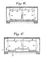
- the method according to the invention is not limited to the production of simple tunnels, such as those described above, and an example of which is illustrated in section in FIG. 8, allowing circulation along two parallel lanes, but also lends itself to the production of tunnels of greater width, for example, a tunnel of double width, as illustrated in section in FIG. 16.
- This tunnel comprises intermediate columns 52 arranged along the median axis of the tunnel. Each of these columns 52 supports the inner ends of two upper beams 53 perpendicular to the axis of the tunnel, the outer ends of which are supported by lintels 27 and concreted to vertical columns 34 (not shown) in the manner described above.
- the beams 53 are joined together and with the column 52 which supports them, the assembly thus obtained forming a double gantry secured to the raft.
- Fig. 17 shows a particular embodiment of a double tunnel, using upper beams 54 of greater length, which allows the development of a central landing platform 55, between the traffic lanes.
- the width of the tunnel can be increased as desired, as required, thanks to the multiplication of intermediate elements (columns 52, upper beams, etc.).
- the method according to the invention also lends itself to the production of intermediate tunnel sections, for joining, for example, a single tunnel section (line) to a double tunnel section (station), passing through intermediate widths .
Abstract
Description
La présente invention se rapporte à une procédé pour construire des tunnels au moyen d'éléments préfabriqués en béton, solidarisés entre eux sur chantier par bétonnage.The present invention relates to a method for constructing tunnels by means of prefabricated concrete elements, joined together on site by concreting.
La réalisation de tunnels se fait généralement par construction de tronçons successifs. Les procédés les plus courants actuellement dans ce domaine sont :
- le procédé en fouilles ouvertes, suivant lequel on réalise dans une tranchée ouverte un cadre en béton armé composé d'un radier, de voiles verticaux et de dalles supérieures, et
- le procédé en fouilles blindées, suivant lequel on effectue un blindage latéral de la fouille avant de réaliser un cadre en béton armé comme ci-dessus. Suivant ce procédé, on peut également réaliser les voiles du tronçon de tunnel à l'aide du blindage latéral de la fouille, ou par des murs emboués qui servent de blindage du sol.The realization of tunnels is generally done by construction of successive sections. The most common processes currently in this area are:
- the open excavation process, in which an reinforced concrete frame composed of a raft, vertical sails and upper slabs is produced in an open trench, and
- the armored excavation process, according to which a lateral shielding of the excavation is carried out before making a reinforced concrete frame as above. According to this process, the sails of the tunnel section can also be produced using the lateral armor of the excavation, or by mud walls which serve as armor for the ground.
Suivant les procédés courants, les tunnels sont réalisés soit par coulage en place des tronçons de tunnel successifs, soit par alignement de tronçons de tunnel préfabriqués.According to current methods, the tunnels are produced either by pouring successive tunnel sections in place, or by aligning prefabricated tunnel sections.
Le coulage en place de tronçons de tunnel qui est le procédé le plus répandu actuellement, nécessite l'installation de chantiers de longueur relativement importante. En effet, le coulage en place du radier, des voiles verticaux puis des dalles supérieures se fait sur des longueurs de plusieurs dizaines de mètres à la fois, ce qui entraîne que le chantier s'étend sur au moins une longueur égale. En pratique le chantier est même beaucoup plus long, car il s'étend aussi bien en avant de la zone de coulage (terrassement et excavation des tranchées) qu'en arrière de celle-ci (remblayage, recouvrement du tunnel et finition) par rapport au sens d'avancement des travaux.The pouring in place of tunnel sections, which is the most widely used process today, requires the installation of sites of relatively great length. Indeed, the pouring in place of the raft, vertical sails then upper slabs is done on lengths of several tens of meters at a time, which means that the site extends over at least an equal length. In practice, the site is even much longer, because it extends as well in front of the pouring zone (earthworks and excavation of trenches) as behind it (backfilling, covering of the tunnel and finishing) compared in the sense of progress of work.
Le procédé de réalisation de tunnels qui consiste à aligner des tronçons de tunnel préfabriqués permet de réduire la longueur du chantier. En effet, d'une part, au fur et à mesure que les tronçons préfabriqués sont placés, les travaux de remblayage et de finition peuvent être exécutés. D'autre part, il n'est pas nécessaire que la tranchée soit creusée sur une grande longueur; celle-ci peut, en effet, être limitée à une longueur équivalent à quelques tronçons seulement. La longueur du chantier s'en trouve donc réduite.The tunneling process which consists of aligning prefabricated tunnel sections allows the length of the site to be reduced. On the one hand, as the prefabricated sections are placed, the backfilling and finishing work can be carried out. On the other hand, it is not necessary that the trench be dug over a great length; this can, in fact, be limited to a length equivalent to only a few sections. The length of the site is therefore reduced.
Toutefois, la manipulation des tronçons de tunnel préfabriqués nécessite l'utilisation d'engins de levage lourds et encombrants. Ces engins de levage de forte puissance sont, en général, montés sur rails, ce qui en limite l'utilisation (difficultés d'installation qui dépendent de la nature du sol supportant les rails, portée limitée à la longueur des rails de roulement). En effet, même pour des petites sections, les tronçons de tunnel préfabriqués sont d'un poids relativement élevé (de l'ordre de 50 tonnes). De ce fait, le procédé est limité à la construction de tunnels de sections réduites tels des passages pour piétons, véhicules automobiles légers ou métro de petit gabarit (par exemple T.A.U., Transport Automatisé Urbain); pour des sections plus importantes, le poids des tronçons préfabriqués serait en effet excessif.However, handling the prefabricated tunnel sections requires the use of heavy and bulky lifting equipment. These high-power lifting devices are generally mounted on rails, which limits their use (installation difficulties which depend on the nature of the soil supporting the rails, range limited to the length of the running rails). Even for small sections, the prefabricated tunnel sections are relatively heavy (around 50 tonnes). Therefore, the method is limited to the construction of tunnels of reduced sections such as pedestrian crossings, light motor vehicles or small metro (for example T.A.U., Automated Urban Transport); for larger sections, the weight of the prefabricated sections would indeed be excessive.
Un autre problème posé par la construction d'un ouvrage souterrain est que la circulation en surface est fortement perturbée (déviations, construction de viaducs de détournement, etc.) et même dans certains cas, supprimée le long de l'axe des travaux.Another problem posed by the construction of an underground structure is that surface circulation is greatly disturbed (detours, construction of diversion viaducts, etc.) and even in certain cases, eliminated along the axis of the works.
Un autre problème encore est le désagrément de longue durée occasionné aux riverains, provoquée par l'activité du chantier, le mouvement d'engins de levage de grande dimension et les difficultés d'accès entraînées par l'éventrement des chaussées.Yet another problem is the long-term inconvenience caused to residents, caused by the activity of the site, the movement of lifting gear of large dimension and the difficulties of access caused by the eventuality of the pavements.
La présente invention a pour but un procédé pour la construction de tunnels, par assemblage d'éléments préfabriqués qui :
- ne nécessite qu'un chantier de faible longueur,
- s'accommode de sites de travail étroits,
- fait appel à des machines de chantier courantes, de type automoteur, qui constituent une faible nuisance,
- permet le déplacement rapide du chantier le long de l'axe du tunnel, grâce à la répétition d'une série d'opérations simples,
- limite les déplacements de terrain préjudiciables aux constructions adjacentes au chantier,
- demande un front de terrassement réduit, ce qui permet de réaliser des tunnels même au sein d'autres chantiers,
- ne perturbe pas l'assiette du sol, le volume de terre évacué correspondant pratiquement au volume du tunnel.The object of the present invention is a method for the construction of tunnels, by assembling prefabricated elements which:
- only requires a short site,
- accommodates narrow work sites,
- uses common site machinery, self-propelled, which is a low nuisance,
- allows rapid movement of the site along the axis of the tunnel, thanks to the repetition of a series of simple operations,
- limits the displacements of ground prejudicial to the constructions adjacent to the building site,
- requires a reduced earthwork front, which makes it possible to build tunnels even within other construction sites,
- does not disturb the ground level, the volume of evacuated soil practically corresponding to the volume of the tunnel.
Un tel procédé qui limite fortement les désagréments causés auz riverains est donc particulièrement adapté à la réalisation de tunnels en site urbain dense. Par ailleurs, ce procédé
- permet une utilisation rationnelle de la main-d'oeuvre,
-est applicable à des chantiers en sol meuble ou détrempé,
- permet de réaliser indifféremment des tunnels de grande ou de petit section, en passant par des sections intermédiaires.Such a process which greatly limits the inconvenience caused to residents is therefore particularly suitable for the construction of tunnels in dense urban sites. Furthermore, this process
- allows rational use of labor,
-is applicable to sites on loose or soggy ground,
- can be used to make tunnels of large or small section, passing through intermediate sections.
Le procédé suivant la présente invention fait en effet appel à un certain nombre d'éléments préfa briqués standardisés, de poids relativement réduit (environ 10 tonnes), dont la manipulation ne nécessite que des engins de levage plus mobiles, du type couramment employé sur la plupart des chantiers. Ces engins de levage peuvent être des grues automobiles, qu'il n'est pas nécessaire de monter sur rails.The process according to the present invention in fact calls upon a certain number of preferred elements. standardized briquettes, of relatively reduced weight (around 10 tonnes), the handling of which requires only more mobile lifting equipment, of the type commonly used on most construction sites. These lifting devices can be automobile cranes, which do not need to be mounted on rails.
L'utilisation d'éléments préfabriqués standardisés permet au procédé de l'invention de réaliser indifféremment des tunnels de faible section et des tunnels de plus grande section, par exemple pour métro de grand gabarit, chemin de fer souterrain, etc., en juxtaposant un nombre plus ou moins grand de ces éléments standardisés. De plus, comme on le verra plus loin, le procédé suivant l'invention permet de varier la section des tunnels, qui peut ainsi passer d'une section minimale (pour un tronçon de tunnel simple de ligne) à une section maximale (tronçons de tunnel comprenant des gares, avec quais de débarquement, salles d'attente, etc.) en passant par des sections intermédiaires. Il est même possible de réaliser suivant le procédé de l'invention des tunnels à deux niveaux.The use of standardized prefabricated elements makes it possible for the process of the invention to make tunnels of small section and tunnels of larger section, for example for large gauge metro, underground railway, etc., by juxtaposing a greater or lesser number of these standardized elements. In addition, as will be seen below, the method according to the invention makes it possible to vary the section of the tunnels, which can thus pass from a minimum section (for a single tunnel section of line) to a maximum section (sections of tunnel comprising stations, with landing platforms, waiting rooms, etc.) passing through intermediate sections. It is even possible to produce, according to the method of the invention, two-level tunnels.
D'autre part, la manipulation et le placement de ces éléments standardisés est une suite d'opérations répétitives et simples. En effet, les différents éléments préfabriqués composant les voiles verticaux, les dalles supérieures, etc. sont placés un par un comme il sera décrit plus loin; la construction du tunnel se fait donc de manière continue.On the other hand, the handling and placement of these standardized elements is a series of repetitive and simple operations. Indeed, the different prefabricated elements making up the vertical sails, the upper slabs, etc. are placed one by one as will be described later; the tunnel is therefore built continuously.
La présente invention a pour objet un procédé pour la construction d'un tunnel au moyen d'éléments préfabriqués en béton, qui sont solidarisés entre eux par bétonnage, après placement.The present invention relates to a method for the construction of a tunnel by means of prefabricated concrete elements, which are joined together by concreting, after placement.
La construction d'un tunnel suivant la présente invention comprend les phases suivantes :
- creusement, à l'aplomb des parois verticales du tunnel en cours, de fouilles blindées de dimensions légèrement supérieures à celles d'éléments en béton armé préfabriqués destinés à constituer partiellement les parois du tunnel,
- réalisation d'une assise de fondation,
- introduction, mise en place et alignement des éléments verticaux dans leur excavation, chaque élément, espacé du précédent, étant disposé au droit d'un élément semblable disposé de l'autre côté du tunnel,
- remblayage des fouilles au moyen d'un matériau de remblai stabilisé et retrait simultané des blindages,
- préterrassement frontal du volume du tunnel dégageant progressivement le sommet des éléments verticaux d'un tronçon de tunnel,
- pose de linteaux parallèlement à l'axe du tunnel, de manière telle que chaque linteau s'appuie par ses extrémités à la partie supérieure de deux éléments verticaux successifs;
- pose de poutres supérieures transversales, chaque poutre reposant par ses extrémités sur des linteaux disposés en regard l'un de l'autre de part et d'autre du tunnel,
- creusement frontal du volume du tunnel dégageant progressivement chaque paire d'éléments verticaux solidarisés par une poutre transversale, le talon de chaque élément restant toutefois fiché dans le sol,
- pose d'une butée d'entretoisement au droit de l'intervalle séparant deux éléments verticaux successifs,
- remblayage et égalisation du sol de la fouille,
- mise en place, dans chaque intervalle séparant deux éléments verticaux successifs, d'une armature et d'une plaque de coffrage disposée près du bord libre des éléments verticaux parallèlement à l'axe du tunnel,
- coulage de béton entre éléments verticaux successifs,
- introduction d'éléments d'armature au travers d'orifices ménagés au bas des faces latérales des éléments verticaux,
- pose d'une armature pour le radier,
- coulage du radier,
- coulage de béton dans l'intervalle entre deux éléments verticaux successifs,
- pose et solidarisation de prédalles supérieures en béton armé sur les poutres, de manière telle que chaque prédalle s'appuie par son bord avant sur une poutre et par son bord arrière sur la poutre suivante;
- bétonnage de la dalle supérieure et colmatage du tunnel,
- pose d'une couverture d'étanchéité,
- remblayage et recouvrement du tunnel.The construction of a tunnel according to the present invention comprises the following phases:
- excavation, directly above the vertical walls of the tunnel in progress, of armored excavations of dimensions slightly greater than those of prefabricated reinforced concrete elements intended to partially constitute the walls of the tunnel,
- realization of a foundation foundation,
- introduction, positioning and alignment of vertical elements in their excavation, each element, spaced from the previous one, being arranged in line with a similar element placed on the other side of the tunnel,
- backfilling of excavations with stabilized backfill material and simultaneous removal of shields,
- frontal pre-embankment of the volume of the tunnel gradually clearing the top of the vertical elements of a section of tunnel,
- Installation of lintels parallel to the axis of the tunnel, so that each lintel is supported by its ends at the upper part of two successive vertical elements;
- laying of transverse upper beams, each beam resting at its ends on lintels arranged opposite one another on either side of the tunnel,
- frontal digging of the volume of the tunnel gradually releasing each pair of vertical elements secured by a transverse beam, the heel of each element remaining stuck in the ground,
- installation of a bracing stop at the right of the interval separating two successive vertical elements,
- backfilling and leveling of the excavation soil,
- fitting, in each interval separating two successive vertical elements, a frame and a formwork plate placed near the free edge of the vertical elements parallel to the axis of the tunnel,
- concrete pouring between successive vertical elements,
- introduction of reinforcing elements through orifices provided at the bottom of the lateral faces of the vertical elements,
- installation of a reinforcement to erase it,
- pouring the raft,
- pouring concrete in the interval between two successive vertical elements,
- Laying and joining of upper reinforced concrete slabs on the beams, so that each slab is supported by its front edge on a beam and by its rear edge on the next beam;
- concreting of the upper slab and clogging of the tunnel,
- fitting a waterproof cover,
- backfilling and covering of the tunnel.
Suivant une forme d'exécution préférée, les phases successives de réalisation du tunnel sont exécutées dans l'ordre au long du chantier, depuis la mise en place des éléments verticaux jusqu'à la zone de parachèvement où s'effectuent le remblayage et le recouvrement du tunnel achevé.According to a preferred embodiment, the successive phases of realization of the tunnel are executed in order along the construction site, from the installation of the vertical elements to the zone of completion where the backfilling and the covering take place. of the completed tunnel.
Suivant une forme d'exécution préférée, la pose de deux éléments contigus est séparée par un intervalle de temps assurant la stabilisation du matériau de remblai.According to a preferred embodiment, the installation of two contiguous elements is separated by a time interval ensuring the stabilization of the fill material.
Suivant une séquence de placement avantageuse, on met en place successivement sur un tronçon, en deux passes, une paire sur deux d'éléments verticaux se faisant vis-à-vis.According to an advantageous placement sequence, successively placing on a section, in two passes, a pair on two of vertical elements doing opposite.
De façon préférentielle, un tronçon de chantier s'étend sur la longueur correspondant à la pose de six éléments verticaux successifs.Preferably, a section of site extends over the length corresponding to the installation of six successive vertical elements.
Suivant une forme d'exécution avantageuse, les éléments verticaux constituant partiellement les parois latérales du tunnel sont des coques oblongues en béton armé présentant une voûte cylindrique dont la génératrice est parallèle au grand axe des coques; ces coques sont fermées à chacune de leurs extrémités par une base, perpendiculaire à leur grand axe. Ces coques sont disposées de manière telle que leur côté concave soit dirigé vers l'intérieur du tunnel, et que leur voûte soit dirigée vers les parois de la tranchée.According to an advantageous embodiment, the vertical elements partially constituting the side walls of the tunnel are oblong shells of reinforced concrete having a cylindrical arch whose generator is parallel to the major axis of the shells; these shells are closed at each of their ends by a base, perpendicular to their major axis. These shells are arranged in such a way that their concave side is directed towards the interior of the tunnel, and that their arch is directed towards the walls of the trench.
Un élément vertical est avantageusement prolongé, à sa partie inférieure, par un talon qui reste fiché dans le sol lors de l'excavation du volume du tunnel, de manière à assurer le maintien en place de l'élément avant la pose d'une poutre d'étançonnage.A vertical element is advantageously extended, at its lower part, by a heel which remains stuck in the ground during the excavation of the volume of the tunnel, so as to maintain the element in place before the installation of a beam shoring.
De manière plus particulière, les coques présentent deux pans latéraux plans et parallèles prolongeant la voûte de chaque côté de celle-ci.More specifically, the shells have two flat and parallel side panels extending the arch on each side thereof.
Suivant une forme d'exécution préférée, les faces latérales d'une coque présentent, du côté de l'intérieur du tunnel, une feuillure destinée à la mise en place de plaques de coffrage et des alvéoles destinées à l'introduction de broches pour le maintien de ces plaques.According to a preferred embodiment, the lateral faces of a shell have, on the side of the interior of the tunnel, a rebate intended for the installation of formwork plates and cells intended for the introduction of pins for the maintenance of these plates.
Suivant une forme d'exécution particulière, les coques présentent sur les faces extérieures des pans latéraux, près de leur bord dirigé vers l'extérieur du tunnel, une rainure parallèle au grand axe des coques, apte à recevoir le bord latéral d'une plaque de coffrage.According to a particular embodiment, the shells have on the outer faces of the side panels, near their edge directed towards the outside of the tunnel, a groove parallel to the long axis of the shells, capable of receiving the lateral edge of a plate formwork.
Suivant une forme de réalisation particulière, la face arrière d'une coque est prolongée vers le haut par un épaulement formant coffrage lors du bétonnage de la dalle supérieure du tunnel.According to a particular embodiment, the rear face of a shell is extended upwards by a shoulder forming shuttering during concreting of the upper slab of the tunnel.
Suivant une forme d'exécution avantageuse, la face d'une coque tournée vers l'extérieur du tunnel est sensiblement plane et se raccorde perpendiculairement à ses faces latérales.According to an advantageous embodiment, the face of a shell turned towards the outside of the tunnel is substantially planar and is connected perpendicularly to its lateral faces.
Suivant une forme d'exécution avantageuse, les coques présentent sur les faces extérieures latérales des cannelures verticales qui améliorent leur solidarisation avec les éléments du tunnel coulés sur place.According to an advantageous embodiment, the shells have vertical grooves on the lateral external faces which improve their connection with the elements of the tunnel cast on site.
Suivant une forme d'exécution préférée, la coque est pourvue, dans sa partie inférieure, d'ouvertures, dont l'axe est parallèles à l'axe du tunnel, lesquelles sont destinées au passage de pièces d'armature en béton destinées à être noyées dans le béton lors du coulage.According to a preferred embodiment, the shell is provided, in its lower part, with openings, the axis of which is parallel to the axis of the tunnel, which are intended for the passage of concrete reinforcing pieces intended to be embedded in concrete during pouring.
Suivant une forme d'exécution préférée, la tranche des pans latéraux des coques comporte à sa partie supérieure, un évidement destiné à supporter l'extrémité d'un linteau maintenu en place par boulonnage.According to a preferred embodiment, the edge of the side panels of the shells has at its upper part, a recess intended to support the end of a lintel held in place by bolting.
Suivant une forme de mise en oeuvre avantageuse du procédé, la face concave des coques est obturée durant leur mise en place.According to an advantageous form of implementation of the method, the concave face of the shells is closed during their installation.
Suivant une forme d'exécution particulière, les coques sont fermées par un courvercle constitué d'une tôle en acier.According to a particular embodiment, the shells are closed by a cover made of a steel sheet.
L'assemblage d'une poutre, des deux colonnes en béton armé qui supportent chacune des extrémités de cette poutre et le radier supportant chacune de ces colonnes en béton armé, forme un cadre apte à reprendre les pressions verticales exercées par les terres et la voirie supérieures, ainsi que les pressions horizontales de poussée des terres.The assembly of a beam, of the two reinforced concrete columns which support each of the ends of this beam and the raft supporting each of these reinforced concrete columns, forms a framework capable of taking up the vertical pressures exerted by the land and the road network higher, as well as the horizontal earth pressure.
Ainsi que l'on peut le constater, le procédé suivant l'invention présente un certain nombre d'avantages.As can be seen, the method according to the invention has a number of advantages.
La forme en voûte des coques utilisées préférentiellement offre l'avantage de reprendre les charges horizontales de poussée des terres avec des cloisons relativement minces et ne nécessitant pas de renforts additionnels.The arched shape of the hulls preferably used offers the advantage of taking up the horizontal loads of pushing the earth with relatively thin partitions and not requiring additional reinforcements.
Il est d'une exécution facile, notamment grâce à l'utilisation d'éléments préfabriqués de poids relativement réduit (inférieur à 10 tonnes), dont la manipulation ne nécessite que des engins de manutention courants.It is easy to execute, in particular thanks to the use of prefabricated elements of relatively reduced weight (less than 10 tonnes), the handling of which requires only ordinary handling equipment.
Le nombre d'éléments préfabriqués utilisés étant réduit (en effet, il ne comprend principalement que les poutres d'étançonnage, les éléments verticaux formant les parois verticales, les linteaux, les poutres supérieures et le prédalles), la pose de ces éléments est une suite d'opérations répétées, ce qui favorise la rapidité d'exécution.The number of prefabricated elements used being reduced (in fact, it mainly comprises only shoring beams, the vertical elements forming the vertical walls, lintels, upper beams and the slabs), the installation of these elements is a following repeated operations, which promotes speed of execution.
Outre le fait que le chantier cause par lui-même un minimum de nuisance, les riverains le voient progresser très rapidement.In addition to the fact that the site itself causes a minimum of nuisance, local residents see it progress very quickly.
A titre d'exemple, une fois passée la période de démarrage, 25 jours seulement séparent le premier coup de pioche donné devant la maison d'un riverain du dernier coup de pelle de remblayage, ce y compris le bétonnage de la structure, la pose de l'étanchéité et le remblayage. A l'issue de ces 25 jours, le chantier aura progressé de 13,5 mètres suivant l'exemple et sera donc pratiquement deux maisons plus loin.For example, once the start-up period has passed, only 25 days separate the first blow of pickaxe given in front of the house of a local resident from the last blow of backfill shovel, including concreting of the structure, laying waterproofing and backfilling. At the end of these 25 days, the site will have progressed 13.5 meters according to the example and will therefore be practically two houses further.
Les phases d'étalement d'un tronçon de tunnel suivant l'exemple non limitatif ci-dessus se décomposent de la façon suivante :
du 1er au 4ème jour : mise en place préalable dans le sol des éléments verticaux (coques),
du 5ème au 10ème jour : dégagement des têtes de coques, mise en place des linteaux et des poutres transversales, excavation, pose des poutres d'étançonnage, bétonnage des colonnes,
du 10ème au 17ème jour : prise du béton,
du 18ème au 19ème jour : pose de la couverture d'étanchéité,
du 20ème au 24ème jour : séchage de l'étanchéité,
25ème jour : remblai.The spreading phases of a tunnel section according to the nonlimiting example above are broken down as follows:
from 1st to 4th day: prior placement in the floor of vertical elements (shells),
from the 5th to the 10th day: clearing of the hull heads, installation of lintels and transverse beams, excavation, installation of shoring beams, concreting of the columns,
from the 10th to the 17th day: setting of the concrete,
18th to 19th day: fitting the waterproofing cover,
from the 20th to the 24th day: drying of the seal,
25th day: backfill.
Le procédé permet aussi d'étaler les temps de travail sur des tronçons successifs à différents stades d'achèvement de façon telle que la progression du tunnel se poursuit en continu, sans temps morts pour la main-d'oeuvre, même durant le laps de temps nécessaire au durcissement du béton ou lors du séchage des produits appliqués pour la couverture d'étanchéité.The method also makes it possible to spread the working times over successive sections at different stages of completion in such a way that the progression of the tunnel continues continuously, with no downtime for the workforce, even during the lapse of time required for hardening of the concrete or during drying of the products applied for the waterproofing cover.
Le procédé prévoit une première phase de mise en place dans le sol d'éléments verticaux, phase qui peut progresser à son propre rythme en avant du chantier proprement dit, ce qui permet un large étalement des tâches en fonction des contraintes de temps.The process provides for a first phase of placing vertical elements in the ground, a phase which can progress at its own pace ahead of the site itself, which allows a large spread of tasks depending on time constraints.
Les installations du chantier proprement dites occupent également une surface au sol réduite du fait de la mobilité du chantier et du fait de l'usage d'un maximum d'éléments préfabriqués hors site.The site installations themselves also occupy a reduced floor area due to the mobility of the site and the use of a maximum of prefabricated elements off site.
Le procédé permet par ailleurs d'épouser les diverses dénivellations du terrain ainsi que les changements de direction imposés par le tracé, tout en utilisant la majorité des éléments préfabriqués ci-dessus.The process also allows to marry the various unevenness of the terrain as well as the changes of direction imposed by the layout, while using the majority of the prefabricated elements above.
Le procédé décrit permet même de réaliser des tunnels à deux niveaux en exécutant une excavation préalable.The process described even makes it possible to carry out two-level tunnels by performing a preliminary excavation.
Le procédé se prête également à la réalisation de tunnels de diverses largeurs; on peut par exemple, réaliser des passages étroits pour des tronçons en ligne droite, ou des sections plus larges pour des stations, ou encore des sections intermédiaires reliant les tronçons étroits et les tronçons larges. Ainsi qu'il sera décrit plus loin, ces différentes largeurs sont réalisées sans problème avec les éléments préfabriqués déjà décrits.The method also lends itself to the construction of tunnels of various widths; one can for example, make narrow passages for straight sections, or wider sections for stations, or even intermediate sections connecting the narrow sections and the wide sections. As will be described later, these different widths are produced without problem with the prefabricated elements already described.
Le procédé suivant l'invention permet d'allier le gros oeuvre et les parachèvements; en particulier à l'intérieur des stations on peut tirer parti de la forme des coques. Bien sûr, les dimensions de ces coques peuvent varier entre des limites relativement larges, mais suivant une forme d'exécution particulière et avantageuse de l'invention, la largeur de ces coques est comprise entre 2 et 3 mètres. De cette façon, les parois des stations se présentent comme une succession de niches, qui peuvent être aménagées suivant les besoins. On peut par exemple, y installer des cabines téléphoniques, des distributeurs automatiques, des banquettes, etc. En l'occurrence, des banquettes peuvent être avantageusement des nervures de forme quelconque faisant corps avec les coques, réalisées lors de la fabrication en usine de celles-ci.The process according to the invention makes it possible to combine the structural work and the finishing touches; in particular inside the stations one can take advantage of the shape of the hulls. Of course, the dimensions of these shells can vary between relatively wide limits, but according to a particular and advantageous embodiment of the invention, the width of these shells is between 2 and 3 meters. In this way, the walls of the stations are presented as a succession of niches, which can be arranged as required. You can, for example, install phone booths, vending machines, benches, etc. In this case, the benches can advantageously be ribs of any shape forming one body with the shells, produced during the factory manufacture of these.
On peut également tirer partie de l'aspect des coques et des plaques de fermeture intérieures reliant les coques successives entre elles, en modifiant à volonté l'aspect de la matière (coloration, coffrages structurés, habillage intégré, etc.).We can also take advantage of the appearance of the shells and the internal closure plates connecting the successive shells together, by modifying the appearance of the material as desired (coloring, structured formwork, integrated covering, etc.).
De manière analogue, les coques formant les parois du tunnel entre les stations peuvent être aménagées pour recevoir des appareils électriques tels des boîtes de jonction, des dispositifs d'éclairage, de signalisation, etc.Similarly, the shells forming the walls of the tunnel between the stations can be arranged to receive electrical devices such as junction boxes, lighting, signaling devices, etc.
La configuration particulière des parois peut également être exploitée avantageusement sur le plan acoustique. En effet, les sons sont captés par la surface des parois, ce qui abaisse considérablement le niveau acoustique et améliore ainsi le confort des usagers du tunnel, notamment des passagers en attente aux gares.The particular configuration of the walls can also be used advantageously acoustically. Indeed, sounds are picked up by the surface of the walls, which considerably lowers the acoustic level and thus improves the comfort of tunnel users, especially passengers waiting at stations.
L'invention sera décrite plus en détail et de manière non limitative en se référant aux figures annexées, dans lesquelles :
- les Fig. 1
et 2 sont des coupes transversales (avec interruption) du tunnel à deux stades de mise en place des coques;) - la Fig. 3 est une vue en plan schématique d'une séquence de mise en place progressive des éléments verticaux en forme de coque;
- la Fig. 4 est une vue en perspective avec arrachement d'un élément vertical en forme de coque;
- les Fig. 5
et 6 sont des coupes longitudinales du tunnel réalisé suivant le procédé de l'invention; - la Fig. 7 est une vue en perspective avec arrachement partiel d'un chantier de construction d'un tunnel suivant le procédé de l'invention;
- la Fig. 8 est une coupe transversale d'un tunnel simple suivant l'invention;
- la Fig. 9 est une coupe d'un noeud d'armature réalisé à la base d'une colonne, suivant un plan vertical perpendiculaire à l'axe du tunnel;
- la Fig. 10 est une coupe d'une noeud d'armature réalisé à la base d'une colonne, suivant un plan horizontal passant par l'axe d'une poutrelle d'étançonnement;
- la Fig. 11 est une vue en perspective de trois coques successives lorsque l'assiette du tunnel est en pente;
- la Fig. 12 est une vue en perspective d'un linteau utilisé dans l'assemblage de la Fig. 10;
- la Fig. 13 est une coupe suivant un plan horizontal d'une portion de tunnel en courbe;
- la Fig. 14 est une coupe suivant un plan horizontal, avec arrachement partiel, d'une portion de tunnel en milieu aquifère;
- la Fig. 15 est une coupe suivant la ligne XV-XV de la Fig. 14;
- la Fig. 16 est une vue en coupe transversale d'un tunnel double suivant l'invention;
- la Fig. 17 est une coupe transversale d'un tunnel double aménagé en gare.
- Figs. 1 and 2 are cross sections (with interruption) of the tunnel with two stages of hull placement;)
- Fig. 3 is a schematic plan view of a sequence of progressive installation of the vertical shell-shaped elements;
- Fig. 4 is a perspective view with cutaway of a vertical shell-shaped element;
- Figs. 5 and 6 are longitudinal sections of the tunnel produced according to the method of the invention;
- Fig. 7 is a perspective view with partial cutaway of a construction site of a tunnel according to the method of the invention;
- Fig. 8 is a cross section of a simple tunnel according to the invention;
- Fig. 9 is a section through a reinforcement knot produced at the base of a column, along a vertical plane perpendicular to the axis of the tunnel;
- Fig. 10 is a section through a reinforcement knot made at the base of a column, along a horizontal plane passing through the axis of a shoring beam;
- Fig. 11 is a perspective view of three successive hulls when the tunnel attitude is sloping;
- Fig. 12 is a perspective view of a lintel used in the assembly of FIG. 10;
- Fig. 13 is a section along a horizontal plane of a curved tunnel portion;
- Fig. 14 is a section along a horizontal plane, with partial cutaway, of a portion of tunnel in an aquifer;
- Fig. 15 is a section along the line XV-XV of FIG. 14;
- Fig. 16 is a cross-sectional view of a double tunnel according to the invention;
- Fig. 17 is a cross section of a double tunnel laid out as a station.
Les Fig. 1 et 2 montrent deux vues en coupe transversale du tunnel lors de la mise en place préalable des éléments verticaux 1.Figs. 1 and 2 show two cross-sectional views of the tunnel during the prior positioning of the
De part et d'autre du tunnel, à l'aplomb de l'emplacement prévu pour les parois verticales, on a creusé une fouille 2 de dimensions telles que l'on puisse y introduire un élément vertical en forme de coque 1 en béton armé destinée à constituer une partie des parois latérales.On either side of the tunnel, at the base of the space provided for the vertical walls, a
Cette fouille 2 peut être réalisée de façon quelconque, mais on peut avantageusement utiliser une méthode de creusement rapide où la fouille est étançonnée par des blindages 3 métalliques emboîtables glissés en place au fur et à mesure du creusement.This
Une fois la profondeur désirée atteinte, on réalise un assise 4 destinée à faciliter le positionnement de la coque 1 qui est mise en place verticalement dans la fouille 2.Once the desired depth has been achieved, a
Le pied 5 de la coque 1 repose sur l'assise de réglage 4, la face concave 6 de la coque tournée vers l'intérieur du tunnel (futur) est fermée provisoirement par un moyen de fermeture 7 tel qu'une tôle de forme appropriée.The foot 5 of the
La Fig. 2 montre en coupe transversale deux étapes terminales de la mise en place préalable des coques 1. Le blindage 3 est remonté progressivement, cependant que l'on introduit dans l'espace subsistant entre la coque 1 et les flancs de l'excavation 8, un matériau de remblai 9 tel que, par exemple, du laitier stabilisé ou du sable stabilisé.Fig. 2 shows in cross section two final stages of the prior placement of the
Du côté gauche du tunnel, après retrait du blindage 3, la fouille 2 est entièrement comblée. La coque 1 reste enfouie en place jusqu'à ce que le matériau de remblai 9 se soit suffisamment stabilisé.On the left side of the tunnel, after removal of the shield 3, the
La Fig. 4 montre une vue en perspective, avec arrachement, d'une forme particulière d'un élément vertical en forme de coque 1 utilisé dans le procédé de construction suivant l'invention.Fig. 4 shows a perspective view, with cutaway, of a particular shape of a vertical shell-shaped
Cet élément présente une voûte 10 cylindrique dont la génératrice est parallèle à l'axe de la coque. Il est enfermé à chacune de ses extrémités par une base 11 perpendiculaire à son grand axe.This element has a
Deux pans latéraux 12 prolongent la voûte 10 de chaque côté de celle-ci.Two
Dans l'exécution représentée, la face arrière 13 de la coque 1 est pratiquement plane et se raccorde perpendiculairement aux faces latérales 14. Une telle forme contribue à réduire les frais de fabrication de ces éléments qui peuvent être préfabriqués dans des moules de forme standard.In the embodiment shown, the rear face 13 of the
La tranche des pans latéraux 12 comporte, près du sommet de l'élément, un évidement 15 destiné à supporter l'extrémité d'un linteau fixé par boulonnage, comme on le verra à la Fig. 5.The edge of the
Les faces latérales 14 de la coque 1 compor tent, du côté tourné vers l'intérieur du tunnel, une feuillure 16 s'étendant sur toute la hauteur de l'élément, ainsi que des perforations 17 permettant l'insertion de broches destinées au maintien de panneaux de coffrage dans les feuillures 16, comme cela sera décrit plus loin.The lateral faces 14 of the
Les faces latérales 14 de la coque 1 comportent, du côté tourné vers l'extérieur du tunnel, une rainure 18 qui s'étend sur toute la hauteur de la coque 1. Cette rainure 18 permet d'insérer un panneau de coffrage arrière sur tout ou partie de la hauteur de la coque 1.The side faces 14 of the
Ce panneau de coffrage coopère, au moment du bétonnage, avec l'épaulement 19 qui prolonge comme une crête la face arrière 13 de la coque 1.This formwork panel cooperates, at the time of concreting, with the
Entre la rainure 18 et la feuillure 16, les faces latérales 14 de la coque 1 comportent des cannelures verticales 20 destinées à améliorer la solidarisation de la coque 1 avec les éléments en béton armé adjacents.Between the
A sa partie inférieure, la coque 1 est percée d'ouvertures 21 qui traversent les pans latéraux 12 de part en part.At its lower part, the
Le pied de la coque 1 se prolonge par un talon 22 dont la fonction est décrite plus loin.The foot of the
Comme il en a été question plus haut, dans le commentaire concernant la Fig. 1, un moyen de fermeture 7 constitué d'une plaque 23 dotée de raidisseurs 24 est fixée, en l'occurrence par des boulons, devant la face concave 6 de la coque de façon à l'obturer lors de sa mise en place. Cette plaque 23 est découpée de telle façon qu'on puisse mettre en place les linteaux sans devoir la retirer.As discussed above, in the commentary to FIG. 1, a closure means 7 consisting of a
La Fig. 3 montre une séquence avantageuse pour la mise en place des coques.Fig. 3 shows an advantageous sequence for the installation of the shells.
En effet, celles-ci ne sont pas accolées les unes aux autres au long d'une tranchée continue. Les coques sont au contraire mises en place une à une par des fouilles 2 distinctes.Indeed, these are not joined to each other along a continuous trench. The hulls are instead placed one by one by
La séquence décrite à la Fig. 3 est conçue de façon telle qu'elle évite la pose successive de deux éléments contigus, à la fois pour éviter les mouvements de terrain et pour permettre la stabilisation du matériau de remblai 9. Une répartition judicieuse du travail, telle que montrée à la Fig. 3, permet de poser sans problèmes en quatre jours les douze coques 1 correspondant à un tronçon de chantier.The sequence described in FIG. 3 is designed in such a way that it avoids the successive laying of two contiguous elements, both to avoid ground movements and to allow the stabilization of the
A l'issue de cette séquence, toutes les coques d'un tronçon de tunnel sont en place et on peut entamer les phases de construction ultérieures qui comprennent la préterrassement, le dégagement des têtes et la pose des poutrelles comme on le verra dans les figures suivantes.At the end of this sequence, all the hulls of a tunnel section are in place and we can start the subsequent construction phases which include pre-grading, clearing of the heads and the installation of beams as we will see in the figures following.
Les Fig. 5 et 6 montrent par une vue en coupe suivant un plan vertical parallèle à l'axe du tunnel, deux stades successifs d'excavation d'un tunnel réalisé suivant l'invention.Figs. 5 and 6 show in a sectional view along a vertical plane parallel to the axis of the tunnel, two successive stages of excavation of a tunnel produced according to the invention.
La Fig. 5 montre le tunnel après préterrassement d'une première couche de terre 25 dégageant la tête des coques 1 d'un tronçon.Fig. 5 shows the tunnel after pre-excavation of a first layer of
Pour mieux mettre en lumière les possibilités de travail continu offertes par le procédé, on a représenté sur la gauche de la figure la fin du tronçon de chantier précédent où le travail est plus avancé. Le volume de ce tronçon de tunnel précédent est entièrement déblayé. Le front de terrassement 26 monte progressivement depuis la base des coques 1 du tronçon précédent jusqu'au niveau du préterrassement 25 du tronçon en cours.To better highlight the possibilities of continuous work offered by the process, we have shown on the left of the figure the end of the previous section of work where work is more advanced. The volume of this previous tunnel section is completely cleared. The
La pente du front de terrassement 26 est douce de façon que la base des coques 1 non encore solidarisées soit maintenue en place en dépit de la poussée latérale des terres.The slope of the
La Fig. 6 montre la progression du front du terrassement 26 et la solidarisation simultanée des coques 1.Fig. 6 shows the progression of the
Un linteau 27 est fixé en place entre deux coques 1 successives; ces linteaux 27 supportent une poutre transversale 28 qui relie entre eux deux linteaux 27 se faisant vis-à-vis de part et d'autre du tunnel.A
Une poutre transversale 28 étant mise en place, on fait progresser le terrassement 26 sur une distance correspondant à la largeur d'une coque 1.A
Le front de terrassement 26 dégage ainsi successivement chaque paire de coques 1 sur toute leur hauteur. Lorsqu'une coque 1 est entièrement dégagée, la poussée latérale exercée par les terres est compensée provisoirement par le talon 22 qui reste enfoui dans le sol. Les dimensions de ce talon 22 (essentiellement, sa surface frontale) sont déterminées à partir des caractéristiques mécaniques du sol.The
Dès que l'intervalle entre deux coques est dégagé, on y pose la poutre d'étançonnement 29 qui reprend dès lors la poussée exercée sur les faces latérales du tunnel.As soon as the gap between two shells is cleared, the shoring
En cas de fortes poussées latérales, si le sol n'offre pas de garanties mécaniques suffisantes ou pour limiter la hauteur de fiche du talon 22, les effets de la poussée latérale des terres peuvent être repris provisoirement avant la pose des poutres d'étançonnement 29 par un étançon métallique mis en place à la base d'un portique.In the event of strong lateral thrusts, if the ground does not offer sufficient mechanical guarantees or to limit the height of the
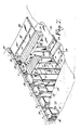
La suite des opérations de construction, suivant le procédé, est décrite en se référant à la Fig. 7 où sont rassemblés plusieurs stades de réalisation successifs.The following construction operations, according to the method, are described with reference to the Fig. 7 where several successive stages of production are gathered.
L'intervalle 30 séparant deux coques 1 successives est dégagé du matériau de remblai 9. On y introduit une armature 31 coopérant avec des éléments longitudinaux d'armature 32 solidarisant le bas des coques 1 d'une même rangée. L'intervalle 30 entre deux coques 1 successives est ensuite fermé par une plaque de coffrage 33 appliquée dans les feuillures 16.The
On coule dans le coffrage ainsi ménagé des colonnes 34 qui forment avec les poutres transversales 28 une suite de portiques aptes à reprendre la poussée des terres.
Par ailleurs, le sol du tunnel étant égalisé, on y pose un treillis d'armature et on y coule une couche de béton qui constitue le radier 35 du tunnel.In addition, the floor of the tunnel being leveled, a reinforcing mesh is placed there and a layer of concrete is poured therein which constitutes the
Dans le sens longitudinal, les armatures 32 introduites au travers des ouvertures 21 pratiquées dans les pans latéraux 12 des coques 1 et prises dans le bas des colonnes 34 forment, une fois le radier 35 coulé, une véritable semelle 36 continue comme on le voit à la Fig. 8 qui soutient le tunnel sur toute sa longueur.In the longitudinal direction, the
Les poutres supérieures transversales 28 supportent des prédalles 37 en béton armé, disposées de manière telle que chaque prédalle 37 s'appuie par son bord avant sur une poutre supérieure transversale 28, et par son bord arrière sur la poutre supérieure transversale 28 suivante.The transverse
Poutres transversales 28 et prédalles 27 forment, par la façon dont elles s'ajustent, un coffrage pour le coulage de la dalle supérieure 38. Les faces latérales de ce coffrage sont constituées par l'épaulement 19 qui prolonge vers le haut la face arrière 13 des coques ainsi que par des panneaux de coffrage 39 insérés dans les rainures 18 ménagées près de l'arête arrière des faces latérales 14 de ces éléments.
Après le bétonnage de la dalle supérieure 38, il est nécessaire de ménager une pause dans les travaux relatifs à un tronçon pour permettre la prise du béton.After the concreting of the
Durant ce temps, la progression du tunnel se poursuit sans interruption par un simple transfert de tâche sur les autres tronçons à divers stades d'achèvement. Après solidification de l'ouvrage, la partie supérieure du tunnel est revêtue d'une couche d'étanchéité et l'on procède au remblayage.During this time, the tunnel progress continues without interruption by a simple task transfer to the other sections at various stages of completion. After the structure has solidified, the upper part of the tunnel is coated with a sealing layer and backfilling is carried out.
La Fig. 8 est une coupe du tunnel, perpendiculairement à son axe, indiquant les trois phases de bétonnage successives nécessaires pour réaliser un portique apte à reprendre les poussées latérales et verticales exercées par les terres sur le tunnel.Fig. 8 is a section through the tunnel, perpendicular to its axis, indicating the three successive concreting phases necessary to produce a gantry capable of taking up the lateral and vertical thrusts exerted by the earth on the tunnel.
La phase 1 concerne le radier 35 et la double semelle longitudinale 36 qui s'étend sur toute la longueur du tunnel.
La phase 2 concerne les colonnes verticales 34 situées entre les coques 1.
La phase 3 concerne la solidarisation de ces colonnes verticales 34, les poutres 28 transversales et la dalle supérieure 38 de la structure.Phase 3 concerns the joining of these
Les Fig. 9 et 10 montrent deux coupes, l'une en élévation, l'autre en plan, de la base d'une colonne 34 joignant deux coques 1. Cet emplacement constitue un véritable noeud dans la structure du tunnel puisque s'y rejoignent des armatures reprenant des sollicitations provenant de trois directions différentes, à savoir les armatures 31 de la colonne verticale 34, non représentée, située entre deux coques 1, l'armature 32, la "poutre" longitudinale 36 qui relie l'ensemble des coques d'une rangée et l'ensemble poutre d'étançon nement 29 et radier 35 qui relie transversalement les deux côtés du tunnel.Figs. 9 and 10 show two sections, one in elevation, the other in plan, of the base of a
Le procédé suivant l'invention a l'avantage de permettre au tunnel d'épouser les diverses dénivellations du terrain ainsi que les changements de hauteur imposés par le tracé.The method according to the invention has the advantage of allowing the tunnel to follow the various unevennesses of the terrain as well as the height changes imposed by the layout.
Un exemple d'un tunnel de ce type est illustré aux Fig. 11 et 12, dans lesquelles les éléments communs à toutes les formes de réalisation décrites ont les mêmes chiffres de référence.An example of such a tunnel is illustrated in Figs. 11 and 12, in which the elements common to all the embodiments described have the same reference numbers.
Les Fig. 11 et 12 illustrent un tunnel à alignement droit dont l'assiette est en pente. Les différentes phases de réalisation sont les mêmes que celles décrites plus haut pour la construction d'un tunnel droit et horizontal. Les coques successives sont mises en place à des niveaux différents suivant la pente du tunnel à construire. Bien entendu, les coques sont mises en place verticalement puisqu'il est essentiel que les colonnes qui seront coulées dans les espaces entre les coques successives soient verticales.Figs. 11 and 12 illustrate a straight-aligned tunnel whose slope is sloping. The different production phases are the same as those described above for the construction of a straight and horizontal tunnel. The successive hulls are placed at different levels depending on the slope of the tunnel to be built. Of course, the shells are placed vertically since it is essential that the columns which will be cast in the spaces between the successive shells are vertical.
La différence de niveau entre deux coques 1 successives nécessite l'utilisation de linteaux 27 d'un type particulier. Un linteau de ce type, ainsi qu'illustré à la Fig. 12, présente à sa surface supérieure deux surfaces d'appui 40 et 41 décalées, séparées par un échelon 42 dont la hauteur est égale à la différence de niveau entre deux coques 1 successives. Les extrémités de deux demi-poutres 43 et 44 viendront s'appuyer respectivement sur les surfaces 40 et 41. Ces poutres 43 et 44 sont, par conséquent, décalées en hauteur l'une par rapport à l'autre. La solidarisation avec les colonnes verticales 34 des demi-poutres 43, 44, se fait de la même manière que dans le cas d'un tunnel à assiette horizontale, ainsi que décrit plus haut. (Insertion d'une armature 31 dans l'espace 30 vertical entre deux coques 1 successives, coulage d'une colonne 34 verticale, solidarisation de chacune des demi-poutres 43 et 44 avec celle-ci). Ainsi que l'on peut le remarquer à la Fig. 11 la demi-poutre la plus haute 43 d'une paire de demi-poutres 43, 44 est à la même hauteur que la demi-poutre la plus basse 33 de la paire de demi-poutres suivante, de manière telle qu'une prédalle 37 s'appuyant par ses extrémités sur ces demi-poutres soit donc sensiblement horizontale. Les travaux de parachèvement du tunnel (bétonnage de la dalle supérieure, étanchéité, recouvrement) sont effectués de la manière décrite plus haut.The difference in level between two
La Fig. 13 illustre un exemple de tunnel en courbe, dans laquelle les éléments communs à toutes les formes de réalisation ont les mêmes chiffres de référence. Les phases de réalisation d'un tunnel en courbe sont les mêmes que précédemment.Fig. 13 illustrates an example of a curved tunnel, in which the elements common to all the embodiments have the same reference numbers. The construction phases of a curved tunnel are the same as before.
L'intervalle entre les coques 1 de la rangée située à l'extérieur de la courbe est supérieur à l'intervalle entre les coques 1 de la rangée située à l'intérieur de la courbe.The interval between the
Par conséquent, les plaques de coffrage verticales 45 entre coques successives 1 (et par suite les armatures 31 qui y sont insérées) de la rangée de coques 1 située à l'extérieur de la courbe, sont plus larges que les plaques de coffrage verticales 46 (et les armatures 31 qui y sont insérées) de la rangée de coques 1 située à l'intérieur de la courbe. Cela nécessite évidemment le placement de linteaux 27 plus longs entre les coques 1 successives de la rangée extérieure de la courbe et le placement de linteaux 27 plus courts entre les coques 1 successives de la rangée intérieure de la courbe.Consequently, the
La Fig. 14 illustre un exemple de tunnel construit en milieu aquifère. Le tronçon illustré est en ligne droite, mais il va de soi que le procédé s'applique aussi bien à un tunnel en alignement courbe qu'à un tunnel dont l'assiette est en pente.Fig. 14 illustrates an example of a tunnel constructed in an aquifer. The section illustrated is in a straight line, but it goes without saying that the method applies as well to a tunnel in curved alignment as to a tunnel whose base is sloping.
Le tronçon de tunnel comprend alors des coques 1 dont la voûte 10 est munie d'ouvertures 47 mettant en communication l'intérieur de celle-ci avec le milieu environnant, et permettant par conséquent, le passage d'eau. La cavité 6 de ces coques est fermée sur toute la hauteur par une cloison verticale 48 munie d'un trou d'accès 49 (Fig. 15). L'intérieur de ces coques se remplit ainsi d'eau jusqu'à un niveau égal au niveau de la nappe.The tunnel section then comprises
Un tuyau 50 transversal situé en dessous du radier 35 relie deux coques 1 de chaque côté du tunnel. Ce tuyau 50 est raccordé à la partie inférieure de chaque coque 1 par un orifice 51 et permet le passage de la nappe souterraine et l'établissement de l'équilibre des niveaux de celle-ci de chaque côté du tunnel.A
Il est évident que cette forme d'exécution nécessite l'utilisation de joints d'étanchéité de type connu, non représentés sur les figures. Ces joins sont placés notamment entre les bases en demi-lune inférieures 11 des coques verticales 1 et le radier 35, d'une part, et les bases 11 en demi-lune supérieures des coques verticales 1 et les prédalles 37, d'autre part.It is obvious that this embodiment requires the use of seals of known type, not shown in the figures. These joints are placed in particular between the lower half-
Le procédé suivant l'invention n'est pas limité à la réalisation de tunnels simples, comme ceux décrits plus haut, et dont un exemple est illustré en coupe à la Fig. 8, permettant la circulation suivant deux voies parallèles, mais se prête également à la réalisation de tunnels de plus grande largeur, par exemple, un tunnel de largeur double, tel qu'illustré en coupe à la Fig. 16. Ce tunnel comprend des colonnes intermédiaires 52 disposées suivant l'axe médian du tunnel. Chacune de ces colonnes 52 supporte les extrémités intérieures de deux poutres supérieures 53 perpendiculaires à l'axe du tunnel dont les extrémités extérieures sont supportées par des linteaux 27 et bétonnées à des colonnes verticales 34 (non représentés) de la manière décrite plus haut. Les poutres 53 sont solidarisées entre elles et avec la colonne 52 qui les supporte, l'ensemble ainsi obtenu formant un portique double solidaire du radier.The method according to the invention is not limited to the production of simple tunnels, such as those described above, and an example of which is illustrated in section in FIG. 8, allowing circulation along two parallel lanes, but also lends itself to the production of tunnels of greater width, for example, a tunnel of double width, as illustrated in section in FIG. 16. This tunnel comprises
La Fig. 17 représente une forme d'exécution particulière de tunnel double, utilisant des poutres supérieures 54 de plus grande longueur, ce qui permet l'aménagement d'un quai de débarquement central 55, entre les voies de circulation.Fig. 17 shows a particular embodiment of a double tunnel, using
Il va de soi que la largeur du tunnel peut être augmentée à souhait, selon les besoins, grâce à la multiplication des éléments intermédiaires (colonnes 52, poutres supérieures, etc.). Le procédé suivant l'invention se prête également à la réalisation de tronçons de tunnel intermédiaires, pour joindre, par exemple, un tronçon de tunnel simple (de ligne) à un tronçon de tunnel double (de gare), en passant par des largeurs intermédiaires.It goes without saying that the width of the tunnel can be increased as desired, as required, thanks to the multiplication of intermediate elements (
Claims (13)
- creusement, à l'aplomb de l'emplacement des parois verticales, de fouilles blindées (2) de dimensions légèrement supérieures à celles d'éléments (1) en béton armé préfabriqués destinés à constituer partiellement les parois du tunnel,
- réalisation d'une assise de fondation (4),
- mise en place d'éléments verticaux (1) dans chaque fouille (2), chaque élément (1), espacé du précédent, étant disposé au droit d'un élément (1) semblable disposé de l'autre côté du tunnel,
- remblayage des fouilles (2) au moyen d'un matériau de remblai stabilisé (9) et retrait simultané des blindages (3),
- préterrassement frontal (25) du volume du tunnel dégageant progressivement le sommet des éléments verticaux (1) d'un tronçon de tunnel,
- pose de linteaux (27) parallèlement à l'axe du tunnel, au droit des intervalles séparant deux éléments verticaux (1), de manière telle que chaque linteau (27) s'appuie par ses extrémités à la partie supérieure de deux éléments verticaux (1) successifs;
- pose de poutres supérieures transversales (28), chaque poutre reposant par ses extrémités sur des linteaux (27) disposés en regard l'un de l'autre de part et d'autre du tunnel,
- creusement frontal (26) du volume du tunnel dégageant progressivement chaque paire d'éléments verticaux (1) solidarisés par une poutre transversale (28), le talon (22) des éléments verticaux restant fiché dans le sol,
- dégagement de l'intervalle (30) séparant deux éléments verticaux (1) successifs,
- pose d'une poutre d'étançonnement (29) au droit de l'intervalle séparant deux éléments successifs,
- introduction d'une armature (31) dans l'espace vertical séparant deux éléments verticaux successifs,
- application d'un panneau de coffrage (33) entre deux éléments verticaux (1) successifs du côté de l'intérieur du tunnel,
- introduction d'éléments d'armature (32) parallèlement à l'axe du tunnel au travers d'orifices (17) ménagés au bas des faces latérales (14) des éléments verticaux.
- coulage de béton dans les coffrages formés entre deux éléments verticaux (1) successifs,
- égalisation du sol de l'excavation,
- pose d'une armature et coulage du radier (35),
- pose de prédalles (37) en béton armé, de manière telle que chaque prédalle prend appui sur deux poutres supérieures (28) transversales successives,
- bétonnage de la dalle supérieure (38) et solidarisation de celle-ci avec les colonnes verticales,
- pose d'un moyen d'étanchéité,
- remblayage et recouvrement du tunnel.Method for the construction of tunnels by means of prefabricated concrete elements, which are joined together after placement, characterized in that it comprises the following phases:
- digging, plumb with the location of the vertical walls, armored excavations (2) of dimensions slightly larger than those of elements (1) in prefabricated reinforced concrete intended to partially constitute the walls of the tunnel,
- realization of a foundation foundation (4),
- installation of vertical elements (1) in each excavation (2), each element (1), spaced from the previous one, being arranged in line with a similar element (1) placed on the other side of the tunnel,
- backfilling of excavations (2) with stabilized backfill material (9) and simultaneous removal of shields (3),
- frontal pre-embedding (25) of the volume of the tunnel progressively clearing the top of the vertical elements (1) of a section of tunnel,
- installation of lintels (27) parallel to the axis of the tunnel, in line with the intervals separating two vertical elements (1), so that each lintel (27) is supported by its ends at the top of two vertical elements (1) successive;
laying of transverse upper beams (28), each beam resting at its ends on lintels (27) arranged opposite one another on either side of the tunnel,
- frontal digging (26) of the volume of the tunnel gradually releasing each pair of vertical elements (1) secured by a transverse beam (28), the heel (22) of the vertical elements remaining stuck in the ground,
- clearance of the interval (30) separating two successive vertical elements (1),
- installation of a shoring beam (29) in line with the interval separating two successive elements,
- introduction of a frame (31) into the vertical space separating two successive vertical elements,
- application of a formwork panel (33) between two successive vertical elements (1) on the inside of the tunnel,
- introduction of reinforcing elements (32) parallel to the axis of the tunnel through orifices (17) formed at the bottom of the lateral faces (14) of the vertical elements.
- pouring concrete into the forms formed between two successive vertical elements (1),
- leveling of the excavation soil,
- fitting a frame and pouring the raft (35),
- laying of reinforced concrete slabs (37), so that each slab rests on two successive transverse upper beams (28),
- concreting of the upper slab (38) and securing it with the vertical columns,
- fitting of a sealing means,
- backfilling and covering of the tunnel.
Priority Applications (3)
| Application Number | Priority Date | Filing Date | Title |
|---|---|---|---|
| EP86870058A EP0242497B1 (en) | 1986-04-25 | 1986-04-25 | Tunnel construction process |
| DE8686870058T DE3660932D1 (en) | 1986-04-25 | 1986-04-25 | Tunnel construction process |
| AT86870058T ATE37929T1 (en) | 1986-04-25 | 1986-04-25 | TUNNEL PROCESS. |
Applications Claiming Priority (1)
| Application Number | Priority Date | Filing Date | Title |
|---|---|---|---|
| EP86870058A EP0242497B1 (en) | 1986-04-25 | 1986-04-25 | Tunnel construction process |
Publications (2)
| Publication Number | Publication Date |
|---|---|
| EP0242497A1 true EP0242497A1 (en) | 1987-10-28 |
| EP0242497B1 EP0242497B1 (en) | 1988-10-12 |
Family
ID=8196539
Family Applications (1)
| Application Number | Title | Priority Date | Filing Date |
|---|---|---|---|
| EP86870058A Expired EP0242497B1 (en) | 1986-04-25 | 1986-04-25 | Tunnel construction process |
Country Status (3)
| Country | Link |
|---|---|
| EP (1) | EP0242497B1 (en) |
| AT (1) | ATE37929T1 (en) |
| DE (1) | DE3660932D1 (en) |
Cited By (6)
| Publication number | Priority date | Publication date | Assignee | Title |
|---|---|---|---|---|
| GR1001467B (en) * | 1991-02-20 | 1994-01-31 | Kosm Georgios | Novel method for the rapid construction of urban electrical undergrounds (metros). |
| ES2052433A2 (en) * | 1992-02-13 | 1994-07-01 | Codelfa Prefabbricati S P A | System for the construction of artificial galleries with prefabricated concrete elements |
| EP0736665A2 (en) * | 1995-04-05 | 1996-10-09 | LIPSKER & PARTNERS ENGINEERING SERVICES (1975) LTD. | Construction of holes and tunnels having support walls |
| CN110863515A (en) * | 2019-12-17 | 2020-03-06 | 中铁二局集团有限公司 | Bottom backfill structure of common-wall tunnel group and construction method thereof |
| CN115354693A (en) * | 2022-10-19 | 2022-11-18 | 中国铁路设计集团有限公司 | Open trench tunnel assembly type U-shaped groove structure and construction method |
| CN115492216A (en) * | 2022-09-30 | 2022-12-20 | 中铁八局集团电务工程有限公司 | Supporting device for transferring pipeline to upper part of underground station and construction method |
Citations (4)
| Publication number | Priority date | Publication date | Assignee | Title |
|---|---|---|---|---|
| DE446535C (en) * | 1927-07-05 | Ignaz Beissel Dr | Reinforced concrete track extension for mines | |
| FR685548A (en) * | 1928-11-29 | 1930-07-11 | reinforced concrete elements for the construction of conduits, shafts, mine galleries, etc. | |
| BE785886A (en) * | 1972-07-05 | 1972-11-03 | Const & Entrepr Ind | CONSTRUCTION PROCESS OF UNDERGROUND WORKING WALLS |
| FR2291344A1 (en) * | 1974-11-12 | 1976-06-11 | Alpina Spa | PREFABRICATED ELEMENT FOR THE CONSTRUCTION OF TRENCH WORKS AND RELATED PROCESS |
-
1986
- 1986-04-25 DE DE8686870058T patent/DE3660932D1/en not_active Expired
- 1986-04-25 AT AT86870058T patent/ATE37929T1/en not_active IP Right Cessation
- 1986-04-25 EP EP86870058A patent/EP0242497B1/en not_active Expired
Patent Citations (4)
| Publication number | Priority date | Publication date | Assignee | Title |
|---|---|---|---|---|
| DE446535C (en) * | 1927-07-05 | Ignaz Beissel Dr | Reinforced concrete track extension for mines | |
| FR685548A (en) * | 1928-11-29 | 1930-07-11 | reinforced concrete elements for the construction of conduits, shafts, mine galleries, etc. | |
| BE785886A (en) * | 1972-07-05 | 1972-11-03 | Const & Entrepr Ind | CONSTRUCTION PROCESS OF UNDERGROUND WORKING WALLS |
| FR2291344A1 (en) * | 1974-11-12 | 1976-06-11 | Alpina Spa | PREFABRICATED ELEMENT FOR THE CONSTRUCTION OF TRENCH WORKS AND RELATED PROCESS |
Cited By (8)
| Publication number | Priority date | Publication date | Assignee | Title |
|---|---|---|---|---|
| GR1001467B (en) * | 1991-02-20 | 1994-01-31 | Kosm Georgios | Novel method for the rapid construction of urban electrical undergrounds (metros). |
| ES2052433A2 (en) * | 1992-02-13 | 1994-07-01 | Codelfa Prefabbricati S P A | System for the construction of artificial galleries with prefabricated concrete elements |
| EP0736665A2 (en) * | 1995-04-05 | 1996-10-09 | LIPSKER & PARTNERS ENGINEERING SERVICES (1975) LTD. | Construction of holes and tunnels having support walls |
| EP0736665A3 (en) * | 1995-04-05 | 1997-11-19 | LIPSKER & PARTNERS ENGINEERING SERVICES (1975) LTD. | Construction of holes and tunnels having support walls |
| CN110863515A (en) * | 2019-12-17 | 2020-03-06 | 中铁二局集团有限公司 | Bottom backfill structure of common-wall tunnel group and construction method thereof |
| CN115492216A (en) * | 2022-09-30 | 2022-12-20 | 中铁八局集团电务工程有限公司 | Supporting device for transferring pipeline to upper part of underground station and construction method |
| CN115492216B (en) * | 2022-09-30 | 2023-07-04 | 中铁八局集团电务工程有限公司 | Supporting device for pipeline to be moved to above underground station and construction method |
| CN115354693A (en) * | 2022-10-19 | 2022-11-18 | 中国铁路设计集团有限公司 | Open trench tunnel assembly type U-shaped groove structure and construction method |
Also Published As
| Publication number | Publication date |
|---|---|
| DE3660932D1 (en) | 1988-11-17 |
| EP0242497B1 (en) | 1988-10-12 |
| ATE37929T1 (en) | 1988-10-15 |
Similar Documents
| Publication | Publication Date | Title |
|---|---|---|
| CA1217349A (en) | Engineering of reinforced concrete structures, such as tunnels, underpasses and the like, and precast concrete elements used in said engineering processes | |
| EP0489054B1 (en) | Cellular structures for sustaining walls | |
| CH642416A5 (en) | METHOD OF CONSTRUCTING UNDERGROUND WORKS WITH VERTICAL WALLS, DEVICE FOR EXECUTING THE METHOD AND UNDERGROUND WORK. | |
| WO2013038071A1 (en) | Method for building structures, particularly passages under operating railways or the like. | |
| EP0463925B1 (en) | Construction method adjacent to mountain side, of a semi-buried structure and thus realized structure | |
| WO1986000358A1 (en) | Method and equipement for making a rigid slab enabling to carry a building | |
| JP4881555B2 (en) | Construction method of underground structure | |
| EP0245155B1 (en) | Process for carrying out works under railway tracks in operation | |
| EP0197021B1 (en) | Method for driving a tunnel | |
| EP0242497B1 (en) | Tunnel construction process | |
| EP0560660B1 (en) | Multistorey underground garages and construction method thereof | |
| BE1001360A3 (en) | Deck semi-prefabricated. | |
| EP0165355A1 (en) | Method of realizing a basement underneath an existing structure | |
| CH434335A (en) | Method of construction of a passage under track and installation for the implementation of this method | |
| FR2727447A1 (en) | Construction of tunnel under embankment in soft soils or areas prone to flooding | |
| FR2824851A1 (en) | PREFABRICATED BRIDGE SUPPORT | |
| FR2839990A1 (en) | Prefabricated Civil engineering structure for installing passage under rail track comprises portico with upper crosspiece connecting two vertical abutments extended by additional spans supported by cover plate on talus ridge | |
| WO1990001089A1 (en) | Process for repairing foundations including damaged pile heads, in particular for timber piles | |
| BE894650R (en) | Reinforced concrete construction underground - has frames dropped into excavations with positioning detents ensuring continuity | |
| FR2472074A1 (en) | Reinforcement for open excavations - provides temporary side protection from rocks using vertical plates permitting introduction of tubular coffer pieces | |
| EP0418162A1 (en) | Process for constructing structures, in particular railway underpasses | |
| FR2610339A1 (en) | Method for constructing building substructures and means for implementing the said method | |
| FR3126717A1 (en) | Foundation piece for point foundations, in particular at the property line, and process for manufacturing a floor | |
| FR2894267A1 (en) | Outer separation structure manufacturing method for forming e.g. partition wall, involves pouring grout of hardenable material in formwork to form anchoring units such that formwork and excavations are simultaneously filled with grout | |
| BE864136A (en) | METHOD AND DEVICE FOR CONSTRUCTION IN THE SOIL OF VERTICAL WALLS FROM AN UNDERGROUND DUCT |
Legal Events
| Date | Code | Title | Description |
|---|---|---|---|
| PUAI | Public reference made under article 153(3) epc to a published international application that has entered the european phase |
Free format text: ORIGINAL CODE: 0009012 |
|
| AK | Designated contracting states |
Kind code of ref document: A1 Designated state(s): AT BE CH DE FR GB IT LI LU NL SE |
|
| 17P | Request for examination filed |
Effective date: 19871010 |
|
| 17Q | First examination report despatched |
Effective date: 19880129 |
|
| GRAA | (expected) grant |
Free format text: ORIGINAL CODE: 0009210 |
|
| AK | Designated contracting states |
Kind code of ref document: B1 Designated state(s): AT BE CH DE FR GB IT LI LU NL SE |
|
| PG25 | Lapsed in a contracting state [announced via postgrant information from national office to epo] |
Ref country code: IT Free format text: LAPSE BECAUSE OF FAILURE TO SUBMIT A TRANSLATION OF THE DESCRIPTION OR TO PAY THE FEE WITHIN THE PRE;WARNING: LAPSES OF ITALIAN PATENTS WITH EFFECTIVE DATE BEFORE 2007 MAY HAVE OCCURRED AT ANY TIME BEFORE 2007. THE CORRECT EFFECTIVE DATE MAY BE DIFFERENT FROM THE ONE RECORDED.SCRIBED TIME-LIMIT Effective date: 19881012 Ref country code: SE Effective date: 19881012 Ref country code: GB Free format text: LAPSE BECAUSE OF NON-PAYMENT OF DUE FEES Effective date: 19881012 Ref country code: AT Effective date: 19881012 |
|
| REF | Corresponds to: |
Ref document number: 37929 Country of ref document: AT Date of ref document: 19881015 Kind code of ref document: T |
|
| REF | Corresponds to: |
Ref document number: 3660932 Country of ref document: DE Date of ref document: 19881117 |
|
| GBV | Gb: ep patent (uk) treated as always having been void in accordance with gb section 77(7)/1977 [no translation filed] | ||
| PG25 | Lapsed in a contracting state [announced via postgrant information from national office to epo] |
Ref country code: LU Free format text: LAPSE BECAUSE OF NON-PAYMENT OF DUE FEES Effective date: 19890430 |
|
| PLBE | No opposition filed within time limit |
Free format text: ORIGINAL CODE: 0009261 |
|
| STAA | Information on the status of an ep patent application or granted ep patent |
Free format text: STATUS: NO OPPOSITION FILED WITHIN TIME LIMIT |
|
| 26N | No opposition filed | ||
| PGFP | Annual fee paid to national office [announced via postgrant information from national office to epo] |
Ref country code: FR Payment date: 19900328 Year of fee payment: 5 |
|
| PGFP | Annual fee paid to national office [announced via postgrant information from national office to epo] |
Ref country code: CH Payment date: 19900330 Year of fee payment: 5 |
|
| PGFP | Annual fee paid to national office [announced via postgrant information from national office to epo] |
Ref country code: LU Payment date: 19900406 Year of fee payment: 5 |
|
| PGFP | Annual fee paid to national office [announced via postgrant information from national office to epo] |
Ref country code: NL Payment date: 19900430 Year of fee payment: 5 |
|
| PGFP | Annual fee paid to national office [announced via postgrant information from national office to epo] |
Ref country code: BE Payment date: 19900613 Year of fee payment: 5 |
|
| PGFP | Annual fee paid to national office [announced via postgrant information from national office to epo] |
Ref country code: DE Payment date: 19900618 Year of fee payment: 5 |
|
| PG25 | Lapsed in a contracting state [announced via postgrant information from national office to epo] |
Ref country code: CH Effective date: 19910430 Ref country code: LI Effective date: 19910430 Ref country code: BE Effective date: 19910430 |
|
| BERE | Be: lapsed |
Owner name: S.A. ENTREPRISES KOECKELBERG Effective date: 19910430 |
|
| PG25 | Lapsed in a contracting state [announced via postgrant information from national office to epo] |
Ref country code: NL Effective date: 19911101 |
|
| NLV4 | Nl: lapsed or anulled due to non-payment of the annual fee | ||
| PG25 | Lapsed in a contracting state [announced via postgrant information from national office to epo] |
Ref country code: FR Effective date: 19911230 |
|
| REG | Reference to a national code |
Ref country code: CH Ref legal event code: PL |
|
| PG25 | Lapsed in a contracting state [announced via postgrant information from national office to epo] |
Ref country code: DE Effective date: 19920201 |
|
| REG | Reference to a national code |
Ref country code: FR Ref legal event code: ST |