EP0600708B1 - Reflection type mask and manufacture of microdevices using the same - Google Patents
Reflection type mask and manufacture of microdevices using the same Download PDFInfo
- Publication number
- EP0600708B1 EP0600708B1 EP93309540A EP93309540A EP0600708B1 EP 0600708 B1 EP0600708 B1 EP 0600708B1 EP 93309540 A EP93309540 A EP 93309540A EP 93309540 A EP93309540 A EP 93309540A EP 0600708 B1 EP0600708 B1 EP 0600708B1
- Authority
- EP
- European Patent Office
- Prior art keywords
- type mask
- reflection type
- film
- multilayered film
- mask
- Prior art date
- Legal status (The legal status is an assumption and is not a legal conclusion. Google has not performed a legal analysis and makes no representation as to the accuracy of the status listed.)
- Expired - Lifetime
Links
- 238000004519 manufacturing process Methods 0.000 title claims description 13
- 238000000034 method Methods 0.000 claims description 35
- 239000000463 material Substances 0.000 claims description 11
- 230000010363 phase shift Effects 0.000 claims description 9
- 230000005855 radiation Effects 0.000 claims description 9
- 239000000758 substrate Substances 0.000 claims description 8
- 238000002310 reflectometry Methods 0.000 claims description 6
- 238000010884 ion-beam technique Methods 0.000 claims description 5
- 230000001678 irradiating effect Effects 0.000 claims description 5
- 238000010894 electron beam technology Methods 0.000 claims description 4
- 238000001015 X-ray lithography Methods 0.000 claims description 2
- 230000003247 decreasing effect Effects 0.000 claims description 2
- 239000004065 semiconductor Substances 0.000 description 11
- 230000003287 optical effect Effects 0.000 description 5
- 239000011358 absorbing material Substances 0.000 description 3
- 230000000694 effects Effects 0.000 description 3
- 238000010438 heat treatment Methods 0.000 description 3
- 238000003384 imaging method Methods 0.000 description 3
- 238000001459 lithography Methods 0.000 description 3
- OKTJSMMVPCPJKN-UHFFFAOYSA-N Carbon Chemical compound [C] OKTJSMMVPCPJKN-UHFFFAOYSA-N 0.000 description 2
- ZOKXTWBITQBERF-UHFFFAOYSA-N Molybdenum Chemical compound [Mo] ZOKXTWBITQBERF-UHFFFAOYSA-N 0.000 description 2
- XUIMIQQOPSSXEZ-UHFFFAOYSA-N Silicon Chemical compound [Si] XUIMIQQOPSSXEZ-UHFFFAOYSA-N 0.000 description 2
- 230000015572 biosynthetic process Effects 0.000 description 2
- 229910052799 carbon Inorganic materials 0.000 description 2
- 238000005530 etching Methods 0.000 description 2
- 238000002474 experimental method Methods 0.000 description 2
- 150000002500 ions Chemical class 0.000 description 2
- 239000004973 liquid crystal related substance Substances 0.000 description 2
- 229910052750 molybdenum Inorganic materials 0.000 description 2
- 239000011733 molybdenum Substances 0.000 description 2
- 230000002093 peripheral effect Effects 0.000 description 2
- 229910052710 silicon Inorganic materials 0.000 description 2
- 239000010703 silicon Substances 0.000 description 2
- WFKWXMTUELFFGS-UHFFFAOYSA-N tungsten Chemical compound [W] WFKWXMTUELFFGS-UHFFFAOYSA-N 0.000 description 2
- 229910052721 tungsten Inorganic materials 0.000 description 2
- 239000010937 tungsten Substances 0.000 description 2
- 238000000560 X-ray reflectometry Methods 0.000 description 1
- 238000012938 design process Methods 0.000 description 1
- 230000002708 enhancing effect Effects 0.000 description 1
- PCHJSUWPFVWCPO-UHFFFAOYSA-N gold Chemical compound [Au] PCHJSUWPFVWCPO-UHFFFAOYSA-N 0.000 description 1
- 239000010931 gold Substances 0.000 description 1
- 229910052737 gold Inorganic materials 0.000 description 1
- 238000007689 inspection Methods 0.000 description 1
- 230000010354 integration Effects 0.000 description 1
- 238000001659 ion-beam spectroscopy Methods 0.000 description 1
- 238000001755 magnetron sputter deposition Methods 0.000 description 1
- 238000012986 modification Methods 0.000 description 1
- 230000004048 modification Effects 0.000 description 1
- 230000003647 oxidation Effects 0.000 description 1
- 238000007254 oxidation reaction Methods 0.000 description 1
- 230000001590 oxidative effect Effects 0.000 description 1
- 238000004806 packaging method and process Methods 0.000 description 1
- 229920001296 polysiloxane Polymers 0.000 description 1
- 239000010453 quartz Substances 0.000 description 1
- 238000007789 sealing Methods 0.000 description 1
- 238000000926 separation method Methods 0.000 description 1
- HBMJWWWQQXIZIP-UHFFFAOYSA-N silicon carbide Chemical compound [Si+]#[C-] HBMJWWWQQXIZIP-UHFFFAOYSA-N 0.000 description 1
- 229910010271 silicon carbide Inorganic materials 0.000 description 1
- VYPSYNLAJGMNEJ-UHFFFAOYSA-N silicon dioxide Inorganic materials O=[Si]=O VYPSYNLAJGMNEJ-UHFFFAOYSA-N 0.000 description 1
- 238000007740 vapor deposition Methods 0.000 description 1
Images


Classifications
-
- G—PHYSICS
- G03—PHOTOGRAPHY; CINEMATOGRAPHY; ANALOGOUS TECHNIQUES USING WAVES OTHER THAN OPTICAL WAVES; ELECTROGRAPHY; HOLOGRAPHY
- G03F—PHOTOMECHANICAL PRODUCTION OF TEXTURED OR PATTERNED SURFACES, e.g. FOR PRINTING, FOR PROCESSING OF SEMICONDUCTOR DEVICES; MATERIALS THEREFOR; ORIGINALS THEREFOR; APPARATUS SPECIALLY ADAPTED THEREFOR
- G03F7/00—Photomechanical, e.g. photolithographic, production of textured or patterned surfaces, e.g. printing surfaces; Materials therefor, e.g. comprising photoresists; Apparatus specially adapted therefor
- G03F7/70—Microphotolithographic exposure; Apparatus therefor
- G03F7/70216—Mask projection systems
- G03F7/70283—Mask effects on the imaging process
-
- B—PERFORMING OPERATIONS; TRANSPORTING
- B82—NANOTECHNOLOGY
- B82Y—SPECIFIC USES OR APPLICATIONS OF NANOSTRUCTURES; MEASUREMENT OR ANALYSIS OF NANOSTRUCTURES; MANUFACTURE OR TREATMENT OF NANOSTRUCTURES
- B82Y10/00—Nanotechnology for information processing, storage or transmission, e.g. quantum computing or single electron logic
-
- B—PERFORMING OPERATIONS; TRANSPORTING
- B82—NANOTECHNOLOGY
- B82Y—SPECIFIC USES OR APPLICATIONS OF NANOSTRUCTURES; MEASUREMENT OR ANALYSIS OF NANOSTRUCTURES; MANUFACTURE OR TREATMENT OF NANOSTRUCTURES
- B82Y40/00—Manufacture or treatment of nanostructures
-
- G—PHYSICS
- G03—PHOTOGRAPHY; CINEMATOGRAPHY; ANALOGOUS TECHNIQUES USING WAVES OTHER THAN OPTICAL WAVES; ELECTROGRAPHY; HOLOGRAPHY
- G03F—PHOTOMECHANICAL PRODUCTION OF TEXTURED OR PATTERNED SURFACES, e.g. FOR PRINTING, FOR PROCESSING OF SEMICONDUCTOR DEVICES; MATERIALS THEREFOR; ORIGINALS THEREFOR; APPARATUS SPECIALLY ADAPTED THEREFOR
- G03F1/00—Originals for photomechanical production of textured or patterned surfaces, e.g., masks, photo-masks, reticles; Mask blanks or pellicles therefor; Containers specially adapted therefor; Preparation thereof
- G03F1/22—Masks or mask blanks for imaging by radiation of 100nm or shorter wavelength, e.g. X-ray masks, extreme ultraviolet [EUV] masks; Preparation thereof
- G03F1/24—Reflection masks; Preparation thereof
-
- G—PHYSICS
- G03—PHOTOGRAPHY; CINEMATOGRAPHY; ANALOGOUS TECHNIQUES USING WAVES OTHER THAN OPTICAL WAVES; ELECTROGRAPHY; HOLOGRAPHY
- G03F—PHOTOMECHANICAL PRODUCTION OF TEXTURED OR PATTERNED SURFACES, e.g. FOR PRINTING, FOR PROCESSING OF SEMICONDUCTOR DEVICES; MATERIALS THEREFOR; ORIGINALS THEREFOR; APPARATUS SPECIALLY ADAPTED THEREFOR
- G03F1/00—Originals for photomechanical production of textured or patterned surfaces, e.g., masks, photo-masks, reticles; Mask blanks or pellicles therefor; Containers specially adapted therefor; Preparation thereof
- G03F1/26—Phase shift masks [PSM]; PSM blanks; Preparation thereof
- G03F1/29—Rim PSM or outrigger PSM; Preparation thereof
-
- G—PHYSICS
- G03—PHOTOGRAPHY; CINEMATOGRAPHY; ANALOGOUS TECHNIQUES USING WAVES OTHER THAN OPTICAL WAVES; ELECTROGRAPHY; HOLOGRAPHY
- G03F—PHOTOMECHANICAL PRODUCTION OF TEXTURED OR PATTERNED SURFACES, e.g. FOR PRINTING, FOR PROCESSING OF SEMICONDUCTOR DEVICES; MATERIALS THEREFOR; ORIGINALS THEREFOR; APPARATUS SPECIALLY ADAPTED THEREFOR
- G03F1/00—Originals for photomechanical production of textured or patterned surfaces, e.g., masks, photo-masks, reticles; Mask blanks or pellicles therefor; Containers specially adapted therefor; Preparation thereof
- G03F1/26—Phase shift masks [PSM]; PSM blanks; Preparation thereof
- G03F1/30—Alternating PSM, e.g. Levenson-Shibuya PSM; Preparation thereof
-
- G—PHYSICS
- G03—PHOTOGRAPHY; CINEMATOGRAPHY; ANALOGOUS TECHNIQUES USING WAVES OTHER THAN OPTICAL WAVES; ELECTROGRAPHY; HOLOGRAPHY
- G03F—PHOTOMECHANICAL PRODUCTION OF TEXTURED OR PATTERNED SURFACES, e.g. FOR PRINTING, FOR PROCESSING OF SEMICONDUCTOR DEVICES; MATERIALS THEREFOR; ORIGINALS THEREFOR; APPARATUS SPECIALLY ADAPTED THEREFOR
- G03F7/00—Photomechanical, e.g. photolithographic, production of textured or patterned surfaces, e.g. printing surfaces; Materials therefor, e.g. comprising photoresists; Apparatus specially adapted therefor
- G03F7/20—Exposure; Apparatus therefor
- G03F7/2037—Exposure with X-ray radiation or corpuscular radiation, through a mask with a pattern opaque to that radiation
- G03F7/2039—X-ray radiation
-
- G—PHYSICS
- G03—PHOTOGRAPHY; CINEMATOGRAPHY; ANALOGOUS TECHNIQUES USING WAVES OTHER THAN OPTICAL WAVES; ELECTROGRAPHY; HOLOGRAPHY
- G03F—PHOTOMECHANICAL PRODUCTION OF TEXTURED OR PATTERNED SURFACES, e.g. FOR PRINTING, FOR PROCESSING OF SEMICONDUCTOR DEVICES; MATERIALS THEREFOR; ORIGINALS THEREFOR; APPARATUS SPECIALLY ADAPTED THEREFOR
- G03F7/00—Photomechanical, e.g. photolithographic, production of textured or patterned surfaces, e.g. printing surfaces; Materials therefor, e.g. comprising photoresists; Apparatus specially adapted therefor
- G03F7/70—Microphotolithographic exposure; Apparatus therefor
- G03F7/70216—Mask projection systems
- G03F7/70233—Optical aspects of catoptric systems, i.e. comprising only reflective elements, e.g. extreme ultraviolet [EUV] projection systems
Definitions
- This invention relates generally to a reflection type mask usable, for example, in a lithographic apparatus wherein a radiation energy such as X-rays or vacuum ultraviolet rays is used to project a pattern, with a reflection mirror, onto a resist.
- a radiation energy such as X-rays or vacuum ultraviolet rays is used to project a pattern, with a reflection mirror, onto a resist.
- a radiation energy such as X-rays or vacuum ultraviolet rays having higher resolution has been used to meet higher integration and further miniaturization of each semiconductor device.
- a radiation energy such as X-rays or vacuum ultraviolet rays from a light source source as a synchrotron or a laser plasma is projected to a reflection type mask having a pattern to be transferred. Reflected X-rays or vacuum ultraviolet rays from the mask are projected in a reduced scale onto a resist by using plural reflection mirrors.
- the used reflection type mask generally comprises a reflector on which an absorbing material film or an anti-reflection film is formed in accordance with the pattern to be transferred.
- the reflector may comprise a multilayered film having alternate layers of different materials.
- Phase shift method is known as an expedient for enhancing the resolution of lithography.
- This phase shift method is applicable to a reflection type mask.
- the reflection type mask may comprise a phase shifter by which the phases of X-rays reflected by adjacent patterns of the mask have a mutual phase shift of ⁇ .
- the intensity of the X-rays becomes equal to zero, whereby enhanced contrast is attained.
- the effect of reduction of contrast of the transferred pattern due to diffraction is suppressed without enlarging the numerical aperture of the imaging optical system, and this allows a larger depth of focus. As a result, the effect of a focus error due to wafer alignment error or warp of a wafer is small, and thus enhanced resolution of lithography is attainable.
- a phase shift reflection type mask as disclosed in US-A-5328784 is illustrated in Figure 7, wherein a mask substrate 51 has surface steps 53 and a multilayered film 52 lying thereon. Denoted at 54 are elements of a pattern to be transferred.
- the manufacture of this type mask involves a problem of difficulties in formation of the surface steps. Thus, it is not casy to increase the productivity or yield.
- the present invention provides a reflection type mask comprising:
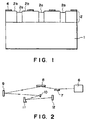
- Figure 1 is a schematic sectional view of a reflection type mask according to a first embodiment of the present invention.
- Figure 2 is a schematic view of a reduction exposure apparatus using a reflection type mask such as shown in Figure 1.
- Figure 4 is a schematic view of a reduction exposure apparatus using a reflection type mask such as shown in Figure 3.
- Figure 5 is a flow chart of semiconductor device manufacturing processes.
- Figure 6 is a flow chart, depicting details of a wafer process.
- a phase shifter is provided with the film thickness period of a multilayered film in a reflecting region being different with location, by which the phase of reflected X-rays is changed.
- the film thickness period of a multilayered film may be changed by locally exposing the film to an energy beam such as an electron beam or ion beam.
- the film thickness period of a multilayered film is p
- the quantity of change of the film thickness period is p'
- the wavelength of used X-rays or vacuum ultraviolet rays is ⁇
- the angle of incidence is ⁇
- the film thickness periodicity is m
- the surface step at the topmost face of the multilayered film is: 2mp'
- phase change of reflected light as X-rays are projected on a multilayered film is not determined by the reflection at the top face only. It is determined also by the reflections at all the interfaces of lower layers. However, in a multilayered film having a sufficient number of accumulated layers to attain high reflectivity, the X-rays reflected at the top face contributes dominantly, such that only the phase change by the reflection at the topmost face may well be taken into account.
- the phase shift quantity may not be exactly equal to ⁇ .
- An effect is obtainable if the quantity is within a range of 0.5 - 1.5 ⁇ .
- the quantity of change of the film thickness period may have a range corresponding to this.
- the film thickness period may be changed by p' which is give by the following relation: 1/2 ⁇ 2mnp'/p ⁇ 3/2 (n is an integer other than zero)
- the multilayered film may be locally heated. This causes an increase or decrease, of a few percentages, of the film thickness period in accordance with the type of the materials constituting the film.
- the quantity of change of the film thickness period can be controlled by heating temperature or heating time.
- irradiation with an energy beam such as an electron beam, an ion beam or a laser beam is preferable.
- a reflection type mask has reflecting areas and non-reflecting areas, by which a mask pattern is defined.
- an energy beam may be projected to destroy the multilayered film structure.
- the non-reflecting areas and phase shifter elements can be produced only by modifying the condition of irradiation in a single energy beam projection process.
- Figure 1 shows a first embodiment, wherein a mask substrate 1 made of quartz has a multilayered film 2 comprising alternate layers of molybdenum and silicone.
- the multilayered film was formed by RF magnetron sputtering method.
- each molybdenum layer has a thickness of 3 nm
- each silicon layer has a thickness of 3.7 nm.
- the number of layers is twenty-five pairs.
- an absorbing material pattern 4 comprising gold of a thickness 100 nm, was formed through an ordinary photolithographic method in accordance with the mask pattern (circuit pattern).
- X-rays of a wavelength 13 nm were projected perpendicularly to the resultant mask.
- Figure 2 shows an example of exposure apparatus using such a reflection type mask.
- Beams from an undulator 6 which is a radiation source for producing soft X-rays of a wavelength 13 nm are expanded by means of two reflection mirrors 7 and 8, and they illuminate a reflection type mask 9 of the type described hereinbefore.
- the soft X-rays having intensities and phases changed by the reflection type mask 9 are reduced by an imaging optical system comprising two reflection mirrors 10 and 11, and they are projected on a resist which is applied to a wafer 12.
- the mask pattern is lithographically transferred to the wafer.
- the reduction ratio was 1/10
- the numerical aperture was 0.06.
- a Schwaltzschild optical system was defined. Reduction exposure experiments were made by using the exposure apparatus described, and a pattern of a linewidth of 90 nm was resolved.
- Figure 3 illustrates another embodiment, wherein a mask substrate 21 made of silicon carbide has a multilayered film 22 comprising alternate layers of tungsten and carbon.
- the multilayered film was formed by ion beam sputtering method.
- each tungsten layer has a thickness of 0.49 nm
- each carbon layer has a thickness of 1.91 nm.
- the number of layers is two hundred and fifty pairs.
- An ion beam was then projected to a peripheral portion 22c of the multilayered film in accordance with a mask pattern (circuit pattern) to locally heat the multilayered film to destroy the multilayered film structure.
- a mask pattern circuit pattern
- the multilayered film was heated and, as a result, the period was increased by about 0.2 %, and the surface step at the surface of the multilayered film had a height of about 1.2 nm.
- X-rays of a wavelength 4.5 nm were projected to the resultant multilayered film with an angle of incidence of 20 deg., and the reflectivity was measured.
- the result is that the portion 22a not irradiated with the ion beam had a reflectivity of 35 %, the destroyed portion 22c had an X-ray reflectivity of not greater than 0.1 %, and the portion 22b in the neighbourhood of it had a reflectivity of 32 %.
- the phases of the reflected X-rays from the portions 22a and 22c had a mutual difference of 0.9 ⁇ .
- non-reflecting areas and phase shifter elements can be formed through a single process.
- it is very effective to improve the mask pattern position precision, the productivity and the yield.
- FIG. 5 is a flow chart of the sequence of manufacturing a semiconductor device such as a semiconductor chip (e.g. IC or LSI), a liquid crystal panel or a CCD, for example.
- Step 1 is a design process for designing the circuit of a semiconductor device.
- Step 2 is a process for manufacturing a mask on the basis of the circuit pattern design.
- Step 3 is a process for manufacturing a wafer by using a material such as silicon.
- Step 4 is a wafer process which is called a pre-process wherein, by using the so prepared mask and wafer, circuits are practically formed on the wafer through lithography.
- Step 5 subsequent to this is an assembling step which is called a post-process wherein the wafer processed by step 4 is formed into semiconductor chips. This step includes assembling (dicing and bonding) and packaging (chip sealing).
- Step 6 is an inspection step wherein operability check, durability check and so on of the semiconductor devices produced by step 5 are carried out. With these processes, semiconductor devices are finished and they are shipped (step 7).
- Step 6 is a flow chart showing details of the wafer process.
- Step 11 is an oxidation process for oxidizing the surface of a wafer.
- Step 12 is a CVD process for forming an insulating film on the wafer surface.
- Step 13 is an electrode forming process for forming electrodes on the wafer by vapor deposition.
- Step 14 is an ion implanting process for implanting ions to the wafer.
- Step 15 is a resist process for applying a resist (photosensitive material) to the wafer.
- Step 16 is an exposure process for printing, by exposure, the circuit pattern of the mask on the wafer through the exposure apparatus described above.
- Step 17 is a developing process for developing the exposed wafer.
- Step 18 is an etching process for removing portions other than the developed resist image.
- Step 19 is a resist separation process for separating the resist material remaining on the wafer after being subjected to the etching process. By repeating these processes, circuit patterns are superposedly formed on the wafer.
Landscapes
- Physics & Mathematics (AREA)
- General Physics & Mathematics (AREA)
- Engineering & Computer Science (AREA)
- Chemical & Material Sciences (AREA)
- Nanotechnology (AREA)
- Crystallography & Structural Chemistry (AREA)
- Toxicology (AREA)
- Theoretical Computer Science (AREA)
- Mathematical Physics (AREA)
- Health & Medical Sciences (AREA)
- Condensed Matter Physics & Semiconductors (AREA)
- Manufacturing & Machinery (AREA)
- Preparing Plates And Mask In Photomechanical Process (AREA)
- Exposure And Positioning Against Photoresist Photosensitive Materials (AREA)
- Exposure Of Semiconductors, Excluding Electron Or Ion Beam Exposure (AREA)
Applications Claiming Priority (2)
| Application Number | Priority Date | Filing Date | Title |
|---|---|---|---|
| JP321908/92 | 1992-12-01 | ||
| JP32190892A JP3219502B2 (ja) | 1992-12-01 | 1992-12-01 | 反射型マスクとその製造方法、並びに露光装置と半導体デバイス製造方法 |
Publications (2)
| Publication Number | Publication Date |
|---|---|
| EP0600708A1 EP0600708A1 (en) | 1994-06-08 |
| EP0600708B1 true EP0600708B1 (en) | 1998-07-22 |
Family
ID=18137750
Family Applications (1)
| Application Number | Title | Priority Date | Filing Date |
|---|---|---|---|
| EP93309540A Expired - Lifetime EP0600708B1 (en) | 1992-12-01 | 1993-11-30 | Reflection type mask and manufacture of microdevices using the same |
Country Status (4)
| Country | Link |
|---|---|
| US (1) | US5503950A (ja) |
| EP (1) | EP0600708B1 (ja) |
| JP (1) | JP3219502B2 (ja) |
| DE (1) | DE69319858T2 (ja) |
Families Citing this family (24)
| Publication number | Priority date | Publication date | Assignee | Title |
|---|---|---|---|---|
| JP3267471B2 (ja) * | 1995-08-02 | 2002-03-18 | キヤノン株式会社 | マスク、これを用いた露光装置やデバイス生産方法 |
| KR0147665B1 (ko) * | 1995-09-13 | 1998-10-01 | 김광호 | 변형조명방법, 이에 사용되는 반사경 및 그 제조방법 |
| US6038279A (en) * | 1995-10-16 | 2000-03-14 | Canon Kabushiki Kaisha | X-ray generating device, and exposure apparatus and semiconductor device production method using the X-ray generating device |
| JP3284045B2 (ja) * | 1996-04-30 | 2002-05-20 | キヤノン株式会社 | X線光学装置およびデバイス製造方法 |
| JP3774522B2 (ja) * | 1996-12-24 | 2006-05-17 | キヤノン株式会社 | 回折光学素子及びそれを有する光学機器 |
| US5962174A (en) * | 1998-02-13 | 1999-10-05 | Micron Technology, Inc. | Multilayer reflective mask |
| US6356340B1 (en) | 1998-11-20 | 2002-03-12 | Advanced Micro Devices, Inc. | Piezo programmable reticle for EUV lithography |
| JP2001057328A (ja) * | 1999-08-18 | 2001-02-27 | Nikon Corp | 反射マスク、露光装置および集積回路の製造方法 |
| US6596465B1 (en) | 1999-10-08 | 2003-07-22 | Motorola, Inc. | Method of manufacturing a semiconductor component |
| US6821682B1 (en) * | 2000-09-26 | 2004-11-23 | The Euv Llc | Repair of localized defects in multilayer-coated reticle blanks for extreme ultraviolet lithography |
| JP2002245947A (ja) * | 2000-12-15 | 2002-08-30 | Canon Inc | 細線を有する基板及びその製造方法及び電子源基板及び画像表示装置 |
| US6645679B1 (en) * | 2001-03-12 | 2003-11-11 | Advanced Micro Devices, Inc. | Attenuated phase shift mask for use in EUV lithography and a method of making such a mask |
| US6428939B1 (en) | 2001-03-20 | 2002-08-06 | Wisconsin Alumni Research Foundation | Enhanced bright peak clear phase shifting mask and method of use |
| FR2825473B1 (fr) * | 2001-06-01 | 2003-11-14 | Xenocs | Procede de modification controlee de proprietes reflectives d'un multicouche |
| EP1395857A2 (fr) * | 2001-06-01 | 2004-03-10 | Xenocs | Procede de modification controlee de proprietes reflectives d'un multicouche |
| US6756158B2 (en) * | 2001-06-30 | 2004-06-29 | Intel Corporation | Thermal generation of mask pattern |
| US6830851B2 (en) * | 2001-06-30 | 2004-12-14 | Intel Corporation | Photolithographic mask fabrication |
| US7022435B2 (en) * | 2002-09-27 | 2006-04-04 | Euv Limited Liability Corporation | Method for the manufacture of phase shifting masks for EUV lithography |
| US6998203B2 (en) * | 2003-08-01 | 2006-02-14 | Intel Corporation | Proximity correcting lithography mask blanks |
| JP4402656B2 (ja) | 2003-09-17 | 2010-01-20 | カール・ツァイス・エスエムティー・アーゲー | マスク及びリソグラフィ装置 |
| NL1036305A1 (nl) | 2007-12-21 | 2009-06-23 | Asml Netherlands Bv | Grating for EUV-radiation, method for manufacturing the grating and wavefront measurement system. |
| US10401723B2 (en) | 2013-06-03 | 2019-09-03 | Asml Netherlands B.V. | Patterning device |
| KR102101837B1 (ko) | 2013-06-11 | 2020-04-17 | 삼성전자 주식회사 | 포토마스크, 포토마스크의 레지스트레이션 에러 보정 방법, 포토마스크를 이용하여 제조된 집적 회로 및 그 제조 방법 |
| KR20230098678A (ko) * | 2020-11-20 | 2023-07-04 | 엔테그리스, 아이엔씨. | 포토리소그래피에 사용하기 위한 위상 시프트 레티클 |
Family Cites Families (11)
| Publication number | Priority date | Publication date | Assignee | Title |
|---|---|---|---|---|
| EP0947882B1 (en) * | 1986-07-11 | 2006-03-29 | Canon Kabushiki Kaisha | X-ray reduction projection exposure system of reflection type |
| JPH0727198B2 (ja) * | 1987-02-18 | 1995-03-29 | キヤノン株式会社 | 多層膜反射型マスク |
| DE3856054T2 (de) * | 1987-02-18 | 1998-03-19 | Canon Kk | Reflexionsmaske |
| JPH01175735A (ja) * | 1987-12-29 | 1989-07-12 | Canon Inc | 反射型マスク及びその製造方法 |
| US5012500A (en) * | 1987-12-29 | 1991-04-30 | Canon Kabushiki Kaisha | X-ray mask support member, X-ray mask, and X-ray exposure process using the X-ray mask |
| JP2710967B2 (ja) * | 1988-11-22 | 1998-02-10 | 株式会社日立製作所 | 集積回路装置の製造方法 |
| JPH02177532A (ja) * | 1988-12-28 | 1990-07-10 | Toshiba Corp | 軟x線反射型露光用マスク及びその製造方法 |
| JPH03266842A (ja) * | 1990-03-16 | 1991-11-27 | Fujitsu Ltd | 反射型ホトリソグラフィ方法、反射型ホトリソグラフィ装置および反射型ホトマスク |
| JP3153230B2 (ja) * | 1990-09-10 | 2001-04-03 | 株式会社日立製作所 | パタン形成方法 |
| JPH0588355A (ja) * | 1991-09-25 | 1993-04-09 | Canon Inc | 反射型マスク及びそれを用いた露光装置 |
| JPH05134385A (ja) * | 1991-11-11 | 1993-05-28 | Nikon Corp | 反射マスク |
-
1992
- 1992-12-01 JP JP32190892A patent/JP3219502B2/ja not_active Expired - Fee Related
-
1993
- 1993-11-30 DE DE69319858T patent/DE69319858T2/de not_active Expired - Fee Related
- 1993-11-30 EP EP93309540A patent/EP0600708B1/en not_active Expired - Lifetime
- 1993-12-01 US US08/158,774 patent/US5503950A/en not_active Expired - Lifetime
Also Published As
| Publication number | Publication date |
|---|---|
| DE69319858T2 (de) | 1998-12-17 |
| DE69319858D1 (de) | 1998-08-27 |
| US5503950A (en) | 1996-04-02 |
| EP0600708A1 (en) | 1994-06-08 |
| JP3219502B2 (ja) | 2001-10-15 |
| JPH06177016A (ja) | 1994-06-24 |
Similar Documents
| Publication | Publication Date | Title |
|---|---|---|
| EP0600708B1 (en) | Reflection type mask and manufacture of microdevices using the same | |
| US5641593A (en) | Lithographic mask and exposure apparatus using the same | |
| US5848119A (en) | Illumination system and exposure apparatus having the same | |
| US6645679B1 (en) | Attenuated phase shift mask for use in EUV lithography and a method of making such a mask | |
| US5995582A (en) | X-ray reduction exposure apparatus and device manufacturing method using the same | |
| US6927004B2 (en) | Mask for use in lithography, method of making a mask, lithographic apparatus, and device manufacturing method | |
| US5549994A (en) | Exposure apparatus and reflection type mask to be used in the same | |
| EP0710890B1 (en) | Device fabrication using DUV/EUV pattern delineation | |
| US6373553B1 (en) | Photo-lithographic method to print a line-space pattern with a pitch equal to half the pitch of the mask | |
| TW567534B (en) | Lithographic projection apparatus, method of manufacturing integrated circuits, method of manufacturing a reflector, and phase shift mask | |
| US5262257A (en) | Mask for lithography | |
| US5889758A (en) | Reflection type mask structure and exposure apparatus using the same | |
| US5572564A (en) | Reflecting photo mask for x-ray exposure and method for manufacturing the same | |
| JP2000206321A (ja) | 回折光学素子、回折光学素子を備えた光学系、回折光学素子の製造方法、回折光学素子を備えた光学系を含む露光装置、及び露光装置を用いたデバイスの製造方法 | |
| US5499076A (en) | Exposure method and apparatus | |
| US6647087B2 (en) | Exposure method | |
| US6324250B1 (en) | Exposure method | |
| JP3658398B2 (ja) | 反射型x線マスク構造体、該マスクを用いたx線露光装置並びに該装置を用いたデバイス製造方法 | |
| JPH0588355A (ja) | 反射型マスク及びそれを用いた露光装置 | |
| EP0997779A1 (en) | Exposure method and x-ray mask structure for use with the same | |
| US20220334462A1 (en) | Photomask and method of fabricating a photomask | |
| US5770335A (en) | Mask and exposure apparatus using the same | |
| JP2002217097A (ja) | 反射型x線マスク構造体、x線露光装置、x線露光方法ならびに該反射型x線マスク構造体を用いたデバイス作製方法 | |
| JP2002313694A (ja) | 反射マスク | |
| EP1081551A2 (en) | Two-dimensional phase element and method of manufacturing the same |
Legal Events
| Date | Code | Title | Description |
|---|---|---|---|
| PUAI | Public reference made under article 153(3) epc to a published international application that has entered the european phase |
Free format text: ORIGINAL CODE: 0009012 |
|
| AK | Designated contracting states |
Kind code of ref document: A1 Designated state(s): DE FR GB NL |
|
| 17P | Request for examination filed |
Effective date: 19941021 |
|
| 17Q | First examination report despatched |
Effective date: 19961113 |
|
| GRAG | Despatch of communication of intention to grant |
Free format text: ORIGINAL CODE: EPIDOS AGRA |
|
| GRAG | Despatch of communication of intention to grant |
Free format text: ORIGINAL CODE: EPIDOS AGRA |
|
| GRAH | Despatch of communication of intention to grant a patent |
Free format text: ORIGINAL CODE: EPIDOS IGRA |
|
| GRAH | Despatch of communication of intention to grant a patent |
Free format text: ORIGINAL CODE: EPIDOS IGRA |
|
| GRAA | (expected) grant |
Free format text: ORIGINAL CODE: 0009210 |
|
| AK | Designated contracting states |
Kind code of ref document: B1 Designated state(s): DE FR GB NL |
|
| PG25 | Lapsed in a contracting state [announced via postgrant information from national office to epo] |
Ref country code: FR Free format text: LAPSE BECAUSE OF FAILURE TO SUBMIT A TRANSLATION OF THE DESCRIPTION OR TO PAY THE FEE WITHIN THE PRESCRIBED TIME-LIMIT Effective date: 19980722 |
|
| REF | Corresponds to: |
Ref document number: 69319858 Country of ref document: DE Date of ref document: 19980827 |
|
| EN | Fr: translation not filed | ||
| PLBE | No opposition filed within time limit |
Free format text: ORIGINAL CODE: 0009261 |
|
| STAA | Information on the status of an ep patent application or granted ep patent |
Free format text: STATUS: NO OPPOSITION FILED WITHIN TIME LIMIT |
|
| 26N | No opposition filed | ||
| REG | Reference to a national code |
Ref country code: GB Ref legal event code: IF02 |
|
| PGFP | Annual fee paid to national office [announced via postgrant information from national office to epo] |
Ref country code: NL Payment date: 20081118 Year of fee payment: 16 |
|
| PGFP | Annual fee paid to national office [announced via postgrant information from national office to epo] |
Ref country code: DE Payment date: 20081130 Year of fee payment: 16 |
|
| PGFP | Annual fee paid to national office [announced via postgrant information from national office to epo] |
Ref country code: GB Payment date: 20081124 Year of fee payment: 16 |
|
| REG | Reference to a national code |
Ref country code: NL Ref legal event code: V1 Effective date: 20100601 |
|
| GBPC | Gb: european patent ceased through non-payment of renewal fee |
Effective date: 20091130 |
|
| PG25 | Lapsed in a contracting state [announced via postgrant information from national office to epo] |
Ref country code: NL Free format text: LAPSE BECAUSE OF NON-PAYMENT OF DUE FEES Effective date: 20100601 |
|
| PG25 | Lapsed in a contracting state [announced via postgrant information from national office to epo] |
Ref country code: DE Free format text: LAPSE BECAUSE OF NON-PAYMENT OF DUE FEES Effective date: 20100601 |
|
| PG25 | Lapsed in a contracting state [announced via postgrant information from national office to epo] |
Ref country code: GB Free format text: LAPSE BECAUSE OF NON-PAYMENT OF DUE FEES Effective date: 20091130 |