EP0600526B1 - Vibrationsvorrichtung für Maschinen - Google Patents
Vibrationsvorrichtung für Maschinen Download PDFInfo
- Publication number
- EP0600526B1 EP0600526B1 EP93200324A EP93200324A EP0600526B1 EP 0600526 B1 EP0600526 B1 EP 0600526B1 EP 93200324 A EP93200324 A EP 93200324A EP 93200324 A EP93200324 A EP 93200324A EP 0600526 B1 EP0600526 B1 EP 0600526B1
- Authority
- EP
- European Patent Office
- Prior art keywords
- shafts
- vibrating
- centers
- masses
- relative
- Prior art date
- Legal status (The legal status is an assumption and is not a legal conclusion. Google has not performed a legal analysis and makes no representation as to the accuracy of the status listed.)
- Expired - Lifetime
Links
- 230000005484 gravity Effects 0.000 claims description 2
- 230000001360 synchronised effect Effects 0.000 claims 2
- 238000004519 manufacturing process Methods 0.000 abstract description 2
- 230000033001 locomotion Effects 0.000 description 2
Images


Classifications
-
- B—PERFORMING OPERATIONS; TRANSPORTING
- B28—WORKING CEMENT, CLAY, OR STONE
- B28B—SHAPING CLAY OR OTHER CERAMIC COMPOSITIONS; SHAPING SLAG; SHAPING MIXTURES CONTAINING CEMENTITIOUS MATERIAL, e.g. PLASTER
- B28B1/00—Producing shaped prefabricated articles from the material
- B28B1/08—Producing shaped prefabricated articles from the material by vibrating or jolting
- B28B1/087—Producing shaped prefabricated articles from the material by vibrating or jolting by means acting on the mould ; Fixation thereof to the mould
- B28B1/0873—Producing shaped prefabricated articles from the material by vibrating or jolting by means acting on the mould ; Fixation thereof to the mould the mould being placed on vibrating or jolting supports, e.g. moulding tables
-
- B—PERFORMING OPERATIONS; TRANSPORTING
- B06—GENERATING OR TRANSMITTING MECHANICAL VIBRATIONS IN GENERAL
- B06B—METHODS OR APPARATUS FOR GENERATING OR TRANSMITTING MECHANICAL VIBRATIONS OF INFRASONIC, SONIC, OR ULTRASONIC FREQUENCY, e.g. FOR PERFORMING MECHANICAL WORK IN GENERAL
- B06B1/00—Methods or apparatus for generating mechanical vibrations of infrasonic, sonic, or ultrasonic frequency
- B06B1/10—Methods or apparatus for generating mechanical vibrations of infrasonic, sonic, or ultrasonic frequency making use of mechanical energy
- B06B1/16—Methods or apparatus for generating mechanical vibrations of infrasonic, sonic, or ultrasonic frequency making use of mechanical energy operating with systems involving rotary unbalanced masses
- B06B1/161—Adjustable systems, i.e. where amplitude or direction of frequency of vibration can be varied
- B06B1/162—Making use of masses with adjustable amount of eccentricity
-
- Y—GENERAL TAGGING OF NEW TECHNOLOGICAL DEVELOPMENTS; GENERAL TAGGING OF CROSS-SECTIONAL TECHNOLOGIES SPANNING OVER SEVERAL SECTIONS OF THE IPC; TECHNICAL SUBJECTS COVERED BY FORMER USPC CROSS-REFERENCE ART COLLECTIONS [XRACs] AND DIGESTS
- Y10—TECHNICAL SUBJECTS COVERED BY FORMER USPC
- Y10T—TECHNICAL SUBJECTS COVERED BY FORMER US CLASSIFICATION
- Y10T74/00—Machine element or mechanism
- Y10T74/18—Mechanical movements
- Y10T74/18056—Rotary to or from reciprocating or oscillating
- Y10T74/18344—Unbalanced weights
Definitions
- the present invention relates to a vibrating arrangement for machinery, which exhibits remarkable advantages and innovations with respect to the present arrangements used with the same or similar purpose.
- a vibrating apparatus which comprises two vibrators fitted in line and rotating in the same direction which cause a multidirectional vibration perpendicularly to the axis of the vibrators.
- Each vibrator comprises two coaxial shafts carrying eccentric masses which may be adjusted in their mutual angular position by an adjustment of two coaxial shafts driven by a motor and able to rotatively slide in their mutual relationship.
- the vibrating arrangement for machinery which is the object of the present invention, has been devised and particularly designed to be used in the vibrocompressing machines in the manufacture of concrete moulded components.
- the vibrating arrangement proposed according to the invention consists in a vibrating unit provided with the features as indicated in claim 1.
- the vibrating table is driven by two vibrating centers made up of rotating shafts around which concentric masses with identical rotation centers are provided, these two vibrating centers being arranged in a parallel relationship, and promoted by a motion drive kinematic chain, capable of ensuring two rotating systems, one of which setting up a rotation while the other not, without stopping the rotation and thus without startings and brakings with the subsequent energy saving and operating time saving and also the least wear in the components.
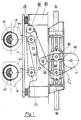
- Figure 1 shows a side view of a vibrating unit according to the invention and a detail of the vibrating centers 2 and 3 at a position where vibration is caused.
- Figure 2 is a view similar to the previous figure but in a position where no vibration is caused, i.e. with operation of cylinders 16 and 17, free pulleys 18 and 19 are moved and eccentric-mass shafts 4 and 5 are duly balanced.
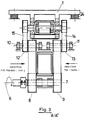
- Figure 3 is a cross-section view along lines A-A' of the preceding figure 2.
- FIG 4 shows the other side view of the unit as illustrated in figure 3 wherein the drive is fixed (pulleys 9 and 13).
- a vibrating arrangement for machinery of the type according to the invention comprises a rotating table 1 driven by two vibrating centers 2 and 3, arranged in a parallel relationship and rotating in opposite directions, each one being provided with two shafts 4 and 5 having eccentric masses with the same rotating center so that when rotating, as shown in figure 2, no vibration is caused while instead when rotating, as shown in figure 1, a vibration is caused.
- a double toothed belt 14 and 15, as illustrated on Fig. 1 to 3 is fitted, said opposite rotation of the two vibrating centers 2 and 3 is originated and consequently likewise an overall one-direction vibration of the vibrating table 1, i.e. downwardly and viceversa on the plane made with both main vibrating centers 2 and 3.
- This vibrating arrangement using the device detailed hereinafter causes a vibration or not (according to positions as in figure 1 or figure 2), all this without stopping rotation, and consequently energy (startings and brakings) is saved, also with the least mechanical wear and many other advantages that are not necessary to be detailed here.
- the operation of the system is driven from a motor 6 such as designated in figure 3 and is started by rotating the interlocked shaft 7 together with two toothed pulleys 8 and 9.
- the independent shafts 10 and 11 are driven by two belt-driving pulleys. These shafts 10 and 11 drive the four shafts with eccentric masses 4 and 5 through their toothed pulleys 12 and 13 and the double toothed belts 14 and 15, the motor driving power being equally shared by the four eccentric mass vibrating shafts and the vibration is caused whenever the shfats are located in the position of figure 1 while no vibration is caused in the position of figure 2.
- the step from the position of figure 1 to that of figure 2 is performed by means of the device of figure 1 and figure 2, comprising two cylinders 16 and 17 (hydraulic or pneumatic) which are shifting the pulleys 18 and 19 from the position of figure 1 to the position of figure 2, i.e. from left to right-hand and vice versa.
- the two vibrating shafts (5) driven by the fixed belt driving unit remain fixed, while otherwise the other two vibrating shafts (4) (figures 1-2) may rotate by 180° which is the same the pulley 12 rotates, with the consequence that the belt 27 in the position of figure 1, when going to the position of figure 2, reduces its length in the side of the pulley 18 and increases its length in the side of the pulley 19, while causing the 180° rotation of the pulley 12 and shaft 10 (all that happening with all devices when rotating).
- Shifting of cylinders 16 and 17 can be varied with the consequence that the positions of the eccentric masses 4 and 5 are also made variable, so that a stronger or weaker vibrating power can thus be achieved.
- antivibrating supports of the vibrating table 1 are shown on columns or bases 25 to which the vibration is not wanted.
Landscapes
- Engineering & Computer Science (AREA)
- Mechanical Engineering (AREA)
- Manufacturing & Machinery (AREA)
- Chemical & Material Sciences (AREA)
- Ceramic Engineering (AREA)
- Apparatuses For Generation Of Mechanical Vibrations (AREA)
- Bridges Or Land Bridges (AREA)
- Turning (AREA)
- Lift-Guide Devices, And Elevator Ropes And Cables (AREA)
- Diaphragms For Electromechanical Transducers (AREA)
- Glass Compositions (AREA)
- Soil Working Implements (AREA)
- Jigging Conveyors (AREA)
- Devices For Conveying Motion By Means Of Endless Flexible Members (AREA)
Claims (4)
- Vibrationseinheit für Maschinen, mit- einem Rahmen (25),- einem Vibrationstisch (1), der vom Rahmen unterstützt wird,- ersten und zweiten Vibrationszentralelementen (2, 3),- wobei jedes Vibrationszentralelement erste (4) und zweite (5) koaxiale drehbare Wellen enthält, die entsprechende erste und zweite exzentrische Massen tragen, wobei die ersten und zweiten exzentrischen Massen jedes Vibrationselements so angeordnet sind, daß sie im Gleichgewicht sind und keine Drehvibration erzeugen, wenn die Massen in einer ersten Stellung angeordnet sind, in der sie sich im wesentlichen in einander gegenüberliegenden Winkelpositionen befinden, und wobei die Massen dann, wenn sie relativ zueinander in eine zweite Position bewegt werden, in der sie beide in derselben Winkelposition angeordnet sind, eine Unwucht erzeugen, wenn das entsprechende Vibrationszentralelement gedreht wird,einer Antriebseinheit, die einen Motor (6) enthält, der mittels erster und zweiter Antriebsriemeneinrichtungen (8-15, 18-19 und 27) die ersten und zweiten Vibrationszentralelemente dreht, und
einer Positionseinstelleinrichtung (16-17), die während der Drehung der Wellen eine Winkeleinstellung der Positionen der ersten Wellen (4) relativ zu den zweiten Wellen (5) bewirkt und eine Winkeleinstellung der exzentrischen Massen auf den ersten Wellen relativ zu den zweiten Wellen ermöglicht,
dadurch gekennzeichnet, daß
die ersten und zweiten Vibrationszentralelemente (2, 3) zueinander parallel Seite an Seite auf dem Tisch montiert sind,
die Antriebseinheit die ersten und zweiten Vibrationszentralelemente in entgegengesetzte Drehrichtungen dreht,
die erste Antriebsriemeneinrichtung (8, 12, 15, 18, 19, 27) die jeweils ersten Wellen (4) der ersten und zweiten Vibrationszentralelemente (2, 3) antreibt, um eine gleichzeitige und synchrone Drehung der ersten Wellen (4) in zueinander entgegensetzten Drehrichtungen zu bewirken,
die zweite Antriebsriemeneinrichtung (9, 11, 13, 14) die jeweils zweiten Wellen (5) der ersten und zweiten Vibrationszentralelemente antreibt, um eine gleichzeitige und synchrone Drehung der jeweiligen zweiten Wellen in zueinander entgegengesetzten Richtungen zu bewirken,
wobei die Vibrationseinheit auf den Tisch eine vertikale Vibrationskraft ausübt, wenn die Massen in der zweiten Position bewegt werden, und
daß die Positionseinstelleinrichtung (16, 17) mit der ersten Antriebsriemeneinrichtung (18, 19, 27) während der Drehung zusammenwirken kann, um eine Winkeleinstellung zu bewirken. - Vibrationseinheit nach Anspruch 1, in der die Positionseinstelleinrichtung (16-17) hydraulische oder pneumatische Zylinder (16, 17) enthält, die mit Riemenscheiben (18, 19) der ersten Antriebsriemeneinrichtung (18, 19, 27) zusammenwirken, um diese quer zu ihrem entsprechenden Riemen (27) zu verschieben, wodurch die Winkeleinstellung der exzentrischen Massen auf den ersten Wellen (4) relativ zu den zweiten Wellen (5) ermöglicht wird.
- Vibrationseinheit nach Anspruch 1, in der die Positionseinstelleinrichtung versehen ist mit einem hydraulischen oder pneumatischen Zylinder oder einer mechanischen Schiebevorrichtung, die mit den Riemenscheiben (18, 19) der ersten Antriebsriemeneinrichtung (18, 19, 27) zusammenwirkt, um diese quer zu ihrem entsprechenden Riemen (27) zu verschieben, wodurch eine Winkeleinstellung der exzentrischen Massen auf den ersten Wellen (4) relativ zu den zweiten Wellen (5) ermöglicht wird, sowie mit einer Kompensationseinrichtung für die Verschiebung wie z. B. Federn, Elektrometer oder Schwerkraft-Gegengewichte, die mit den Riemenscheiben (18, 19) zusammenwirken.
- Vibrationseinheit nach einem der Ansprüche 1 bis 3, in der der Tisch (1) mittels Antivibrationsträgern (24) vom Rahmen (25) getragen wird.
Applications Claiming Priority (2)
| Application Number | Priority Date | Filing Date | Title |
|---|---|---|---|
| ES9203576 | 1992-12-03 | ||
| ES9203576U ES1023151Y (es) | 1992-12-03 | 1992-12-03 | Dispositivo vibrador para maquinaria. |
Publications (2)
| Publication Number | Publication Date |
|---|---|
| EP0600526A1 EP0600526A1 (de) | 1994-06-08 |
| EP0600526B1 true EP0600526B1 (de) | 1997-06-04 |
Family
ID=8280118
Family Applications (1)
| Application Number | Title | Priority Date | Filing Date |
|---|---|---|---|
| EP93200324A Expired - Lifetime EP0600526B1 (de) | 1992-12-03 | 1993-02-05 | Vibrationsvorrichtung für Maschinen |
Country Status (6)
| Country | Link |
|---|---|
| US (1) | US5496167A (de) |
| EP (1) | EP0600526B1 (de) |
| AT (1) | ATE153885T1 (de) |
| DE (1) | DE69311272T2 (de) |
| ES (1) | ES1023151Y (de) |
| MX (1) | MX9304026A (de) |
Families Citing this family (12)
| Publication number | Priority date | Publication date | Assignee | Title |
|---|---|---|---|---|
| FR2722444B1 (fr) * | 1994-07-13 | 1996-08-23 | Ancrenaz Daniel | Dispositif de vibration pour table de presse utilisee pour la fabrication de produits en beton |
| US5584375A (en) * | 1994-12-21 | 1996-12-17 | Food Engineering Corporation | Single drive vibrational conveyor with vibrational motion altering phase control and method of determining optimal conveyance speeds therewith |
| ATE248691T1 (de) * | 1995-10-18 | 2003-09-15 | Cobber Engineering S R L | Vorrichtung zum herstellen von blöcken |
| JP3134050B2 (ja) * | 1996-06-28 | 2001-02-13 | 茂 小林 | コンクリート型枠加振装置 |
| ES2161097B1 (es) * | 1996-10-29 | 2003-11-01 | Prensoland Sa | Dispositivo vibrador para maquinas moldeadoras de piezas de hormigon. |
| DE19814013C1 (de) * | 1998-03-28 | 1999-07-22 | Braun Biotech Int Gmbh | Schüttelvorrichtung und Verfahren zum Schütteln |
| US6112596A (en) * | 1999-03-02 | 2000-09-05 | Qualmark Corporation | Shaker table assembly for a test chamber |
| US6105433A (en) * | 1999-03-02 | 2000-08-22 | Qualmark Corporation | Shaker table assembly for a reliability test chamber utilizing different types of vibrator assemblies |
| ES1059224Y (es) * | 2005-01-04 | 2005-07-01 | Diaz Antonio Poyatos | "dispositivo vibrador para maquinaria perfeccionado" |
| JP4726977B2 (ja) * | 2009-08-24 | 2011-07-20 | Thk株式会社 | 減衰機構付き免震テーブル及びこれを利用した免震テーブルユニット |
| AT520358B1 (de) * | 2017-09-07 | 2019-10-15 | Fill Gmbh | Entkernmaschine zum Entkernen von Gusswerkstücken |
| AT520666B1 (de) | 2017-11-22 | 2020-07-15 | Fill Gmbh | Entkernmaschine zum Entkernen von Gusswerkstücken sowie Verfahren zum Herstellen von Gusswerkstücken |
Family Cites Families (7)
| Publication number | Priority date | Publication date | Assignee | Title |
|---|---|---|---|---|
| FR400510A (fr) * | 1909-03-08 | 1909-07-29 | Lucien Julie | Perfectionnements à la construction des sirènes pour voitures automobiles, canots, etc. |
| US3332293A (en) * | 1963-12-02 | 1967-07-25 | Gen Mills Inc | Vibratory apparatus |
| SE443591B (sv) * | 1981-10-28 | 1986-03-03 | Dynapac Ab | Anordning for kontinuerlig omstellning av vibrationsamplituden hos ett roterbart excenterelement |
| DE3235390C2 (de) * | 1982-09-24 | 1984-09-13 | Thyssen Industrie Ag, 4300 Essen | Rütteltisch |
| FR2647705B1 (fr) * | 1989-06-02 | 1991-08-30 | Balbinot Ets | Installation a table vibrante pour la fabrication de produits en beton |
| FR2659574B1 (fr) * | 1990-03-14 | 1994-07-29 | Bernard Michel | Vibrateur et application de celui-ci a un dispositif de commande en vibration d'une piece, avec amplitude variable. |
| DE4116647C5 (de) * | 1991-05-22 | 2004-07-08 | Hess Maschinenfabrik Gmbh & Co. Kg | Rüttelvorrichtung |
-
1992
- 1992-12-03 ES ES9203576U patent/ES1023151Y/es not_active Expired - Fee Related
-
1993
- 1993-02-05 AT AT93200324T patent/ATE153885T1/de active
- 1993-02-05 DE DE69311272T patent/DE69311272T2/de not_active Expired - Lifetime
- 1993-02-05 EP EP93200324A patent/EP0600526B1/de not_active Expired - Lifetime
- 1993-07-05 MX MX9304026A patent/MX9304026A/es unknown
- 1993-12-02 US US08/161,321 patent/US5496167A/en not_active Expired - Lifetime
Also Published As
| Publication number | Publication date |
|---|---|
| DE69311272T2 (de) | 1998-01-22 |
| ES1023151U (es) | 1993-06-16 |
| ATE153885T1 (de) | 1997-06-15 |
| EP0600526A1 (de) | 1994-06-08 |
| MX9304026A (es) | 1994-06-30 |
| US5496167A (en) | 1996-03-05 |
| ES1023151Y (es) | 1994-01-01 |
| DE69311272D1 (de) | 1997-07-10 |
Similar Documents
| Publication | Publication Date | Title |
|---|---|---|
| EP0600526B1 (de) | Vibrationsvorrichtung für Maschinen | |
| EP0841264B1 (de) | Schwingungsgerät mit Riemenantrieb | |
| US5979640A (en) | Vibrating conveyor drive with continuously adjustable stroke | |
| AU719552B2 (en) | Vibratory drive for a screening machine | |
| RU2262850C2 (ru) | Способ и устройство для формования куска теста | |
| EP0504579B1 (de) | Vorrichtung mit vielfachen Hammerplatten zum Stollen und Geschmeidigmachen von industriellen Fellen und dergleichen | |
| US5496132A (en) | Vibration controller designed in particular for vibrating, tamping and compacting equipment | |
| US3277697A (en) | Vibration testing machine with continuously adjustable amplitude and frequency | |
| NL194008C (nl) | Vibratieheiblok voor het heien en/of trekken van heimateriaal. | |
| EP1048409A1 (de) | Planetengetriebesystem für doppelseitige läppmaschine | |
| US4145156A (en) | Plate vibrator | |
| US4862756A (en) | Adjustable throw eccentric drive | |
| JPH0351538B2 (de) | ||
| EP0025408A2 (de) | Schwingungsgenerator mit veränderbarer Wirkrichtung | |
| US4084446A (en) | Vibratory machine | |
| SU990481A2 (ru) | Плоскодоводочный станок | |
| JPH0711879Y2 (ja) | 平面研削盤のアタッチメント | |
| RU2053866C1 (ru) | Лесопильная рама | |
| JP2001129481A (ja) | 振動篩機及び振動篩設備 | |
| IT9019823A1 (it) | Macchina vibrante, in particolare del tipo alimentatore, vaglio, classificatore, sgrossatore o simile | |
| KR200218384Y1 (ko) | 스크린 진동용 브이벨트 연결장치 | |
| SU919634A1 (ru) | Вибрационный сепаратор семенных смесей | |
| SU1097480A1 (ru) | Устройство дл вибрационно-центробежной обработки | |
| JPS63274508A (ja) | 切断機 | |
| JPH11193169A (ja) | 郵便物取揃装置 |
Legal Events
| Date | Code | Title | Description |
|---|---|---|---|
| PUAI | Public reference made under article 153(3) epc to a published international application that has entered the european phase |
Free format text: ORIGINAL CODE: 0009012 |
|
| AK | Designated contracting states |
Kind code of ref document: A1 Designated state(s): AT BE CH DE DK FR GB GR IE IT LI LU MC NL PT SE |
|
| 17P | Request for examination filed |
Effective date: 19940816 |
|
| 17Q | First examination report despatched |
Effective date: 19941109 |
|
| GRAG | Despatch of communication of intention to grant |
Free format text: ORIGINAL CODE: EPIDOS AGRA |
|
| GRAH | Despatch of communication of intention to grant a patent |
Free format text: ORIGINAL CODE: EPIDOS IGRA |
|
| GRAH | Despatch of communication of intention to grant a patent |
Free format text: ORIGINAL CODE: EPIDOS IGRA |
|
| GRAA | (expected) grant |
Free format text: ORIGINAL CODE: 0009210 |
|
| AK | Designated contracting states |
Kind code of ref document: B1 Designated state(s): AT BE CH DE DK FR GB GR IE IT LI LU MC NL PT SE |
|
| PG25 | Lapsed in a contracting state [announced via postgrant information from national office to epo] |
Ref country code: NL Free format text: LAPSE BECAUSE OF FAILURE TO SUBMIT A TRANSLATION OF THE DESCRIPTION OR TO PAY THE FEE WITHIN THE PRESCRIBED TIME-LIMIT Effective date: 19970604 Ref country code: GR Free format text: LAPSE BECAUSE OF FAILURE TO SUBMIT A TRANSLATION OF THE DESCRIPTION OR TO PAY THE FEE WITHIN THE PRESCRIBED TIME-LIMIT Effective date: 19970604 Ref country code: DK Effective date: 19970604 |
|
| REF | Corresponds to: |
Ref document number: 153885 Country of ref document: AT Date of ref document: 19970615 Kind code of ref document: T |
|
| REG | Reference to a national code |
Ref country code: CH Ref legal event code: EP |
|
| REF | Corresponds to: |
Ref document number: 69311272 Country of ref document: DE Date of ref document: 19970710 |
|
| PG25 | Lapsed in a contracting state [announced via postgrant information from national office to epo] |
Ref country code: SE Effective date: 19970904 |
|
| ET | Fr: translation filed | ||
| REG | Reference to a national code |
Ref country code: CH Ref legal event code: NV Representative=s name: AMMANN PATENTANWAELTE AG BERN Ref country code: CH Ref legal event code: AEN Free format text: DAS PATENT IST AUFGRUND DES WERTERBEHANDLUNGSANTRAGS VOM 06.10.1997 REAKTIVIERT WORDEN. |
|
| NLV1 | Nl: lapsed or annulled due to failure to fulfill the requirements of art. 29p and 29m of the patents act | ||
| REG | Reference to a national code |
Ref country code: PT Ref legal event code: SC4A Free format text: AVAILABILITY OF NATIONAL TRANSLATION Effective date: 19970820 |
|
| PG25 | Lapsed in a contracting state [announced via postgrant information from national office to epo] |
Ref country code: LU Free format text: LAPSE BECAUSE OF NON-PAYMENT OF DUE FEES Effective date: 19980205 Ref country code: IE Free format text: LAPSE BECAUSE OF NON-PAYMENT OF DUE FEES Effective date: 19980205 |
|
| PLBE | No opposition filed within time limit |
Free format text: ORIGINAL CODE: 0009261 |
|
| STAA | Information on the status of an ep patent application or granted ep patent |
Free format text: STATUS: NO OPPOSITION FILED WITHIN TIME LIMIT |
|
| 26N | No opposition filed | ||
| PG25 | Lapsed in a contracting state [announced via postgrant information from national office to epo] |
Ref country code: MC Free format text: LAPSE BECAUSE OF NON-PAYMENT OF DUE FEES Effective date: 19980831 |
|
| REG | Reference to a national code |
Ref country code: GB Ref legal event code: IF02 |
|
| PG25 | Lapsed in a contracting state [announced via postgrant information from national office to epo] |
Ref country code: IT Free format text: LAPSE BECAUSE OF NON-PAYMENT OF DUE FEES Effective date: 20050205 |
|
| PGRI | Patent reinstated in contracting state [announced from national office to epo] |
Ref country code: IT Effective date: 20080301 |
|
| PGFP | Annual fee paid to national office [announced via postgrant information from national office to epo] |
Ref country code: FR Payment date: 20120316 Year of fee payment: 20 Ref country code: CH Payment date: 20120321 Year of fee payment: 20 |
|
| PGFP | Annual fee paid to national office [announced via postgrant information from national office to epo] |
Ref country code: PT Payment date: 20120201 Year of fee payment: 20 |
|
| PGFP | Annual fee paid to national office [announced via postgrant information from national office to epo] |
Ref country code: BE Payment date: 20120224 Year of fee payment: 20 Ref country code: IT Payment date: 20120223 Year of fee payment: 20 Ref country code: GB Payment date: 20120217 Year of fee payment: 20 |
|
| PGFP | Annual fee paid to national office [announced via postgrant information from national office to epo] |
Ref country code: DE Payment date: 20120320 Year of fee payment: 20 |
|
| REG | Reference to a national code |
Ref country code: DE Ref legal event code: R071 Ref document number: 69311272 Country of ref document: DE |
|
| REG | Reference to a national code |
Ref country code: PT Ref legal event code: MM4A Free format text: MAXIMUM VALIDITY LIMIT REACHED Effective date: 20130205 |
|
| REG | Reference to a national code |
Ref country code: GB Ref legal event code: PE20 Expiry date: 20130204 |
|
| BE20 | Be: patent expired |
Owner name: *POYATOS DIAZ ANTONIO Effective date: 20130205 |
|
| REG | Reference to a national code |
Ref country code: AT Ref legal event code: MK07 Ref document number: 153885 Country of ref document: AT Kind code of ref document: T Effective date: 20130205 |
|
| PGFP | Annual fee paid to national office [announced via postgrant information from national office to epo] |
Ref country code: AT Payment date: 20120223 Year of fee payment: 20 |
|
| PG25 | Lapsed in a contracting state [announced via postgrant information from national office to epo] |
Ref country code: DE Free format text: LAPSE BECAUSE OF EXPIRATION OF PROTECTION Effective date: 20130206 Ref country code: GB Free format text: LAPSE BECAUSE OF EXPIRATION OF PROTECTION Effective date: 20130204 |
|
| PG25 | Lapsed in a contracting state [announced via postgrant information from national office to epo] |
Ref country code: PT Free format text: LAPSE BECAUSE OF EXPIRATION OF PROTECTION Effective date: 20130213 |