EP0600325B1 - Bildröhre mit einer Vielzahl von Kanonen - Google Patents
Bildröhre mit einer Vielzahl von Kanonen Download PDFInfo
- Publication number
- EP0600325B1 EP0600325B1 EP93118696A EP93118696A EP0600325B1 EP 0600325 B1 EP0600325 B1 EP 0600325B1 EP 93118696 A EP93118696 A EP 93118696A EP 93118696 A EP93118696 A EP 93118696A EP 0600325 B1 EP0600325 B1 EP 0600325B1
- Authority
- EP
- European Patent Office
- Prior art keywords
- guns
- picture tube
- tube according
- picture
- strips
- Prior art date
- Legal status (The legal status is an assumption and is not a legal conclusion. Google has not performed a legal analysis and makes no representation as to the accuracy of the status listed.)
- Expired - Lifetime
Links
- 230000003287 optical effect Effects 0.000 claims description 14
- OAICVXFJPJFONN-UHFFFAOYSA-N Phosphorus Chemical compound [P] OAICVXFJPJFONN-UHFFFAOYSA-N 0.000 claims description 10
- 239000011159 matrix material Substances 0.000 claims description 6
- 230000007704 transition Effects 0.000 claims description 6
- 238000001514 detection method Methods 0.000 claims 1
- 239000011248 coating agent Substances 0.000 description 4
- 238000000576 coating method Methods 0.000 description 4
- 230000006978 adaptation Effects 0.000 description 1
- XAGFODPZIPBFFR-UHFFFAOYSA-N aluminium Chemical compound [Al] XAGFODPZIPBFFR-UHFFFAOYSA-N 0.000 description 1
- 229910052782 aluminium Inorganic materials 0.000 description 1
- 239000003086 colorant Substances 0.000 description 1
- 238000011161 development Methods 0.000 description 1
- 230000018109 developmental process Effects 0.000 description 1
- 238000010894 electron beam technology Methods 0.000 description 1
- 239000011521 glass Substances 0.000 description 1
- 230000001360 synchronised effect Effects 0.000 description 1
Images
Classifications
-
- H—ELECTRICITY
- H01—ELECTRIC ELEMENTS
- H01J—ELECTRIC DISCHARGE TUBES OR DISCHARGE LAMPS
- H01J31/00—Cathode ray tubes; Electron beam tubes
- H01J31/08—Cathode ray tubes; Electron beam tubes having a screen on or from which an image or pattern is formed, picked up, converted, or stored
- H01J31/10—Image or pattern display tubes, i.e. having electrical input and optical output; Flying-spot tubes for scanning purposes
- H01J31/20—Image or pattern display tubes, i.e. having electrical input and optical output; Flying-spot tubes for scanning purposes for displaying images or patterns in two or more colours
- H01J31/201—Image or pattern display tubes, i.e. having electrical input and optical output; Flying-spot tubes for scanning purposes for displaying images or patterns in two or more colours using a colour-selection electrode
- H01J31/203—Image or pattern display tubes, i.e. having electrical input and optical output; Flying-spot tubes for scanning purposes for displaying images or patterns in two or more colours using a colour-selection electrode with more than one electron beam
-
- H—ELECTRICITY
- H01—ELECTRIC ELEMENTS
- H01J—ELECTRIC DISCHARGE TUBES OR DISCHARGE LAMPS
- H01J2231/00—Cathode ray tubes or electron beam tubes
- H01J2231/12—CRTs having luminescent screens
- H01J2231/125—CRTs having luminescent screens with a plurality of electron guns within the tube envelope
- H01J2231/1255—CRTs having luminescent screens with a plurality of electron guns within the tube envelope two or more neck portions containing one or more guns
Definitions
- the invention is based on a picture tube according to the preamble of claim 1. It is known to create a large screen area with a screen diagonal of ⁇ 40 "from EP 0 356 823 A1, in that several cannons are arranged so that a large screen area with In such solutions, shadow masks are used which considerably reduce the efficiency of the brightness and allow the field transitions to be recognized. The deviation of the electron beam and its brightness are not noticed and corrected.
- the invention has for its object to provide a picture tube without a shadow mask with a variety of cannons, in which the field transitions are imperceptible. This object is achieved by the invention specified in claim 1. Advantageous further developments are specified in the subclaims.
- each cannon is arranged side by side in the vertical and horizontal directions.
- the inside of the screen is coated with blue, green and red vertical phosphor stripes and these are separated by opaque stripes, preferably black matrix stripes.
- black matrix stripe areas there are index areas that are used for vertical and horizontal position finding of the beam.
- the cannons arranged in the vertical direction form a column, and each column has at least one optical sensor to determine the position and the brightness of the beam. In the event of deviations, readjustments are made in the horizontal and vertical directions and the brightness is adjusted so that the sub-picture transitions cannot be seen.
- the individual columns are separated by optical walls that are on the inside of the screen, but each cannon writes its own drawing file on the screen.
- the sequence of the drawing files results on the screen the entire image, in which no partial image transition can be seen due to the brightness-continuous transitions.
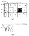
- Fig. 1 shows a screen of the picture tube, which is equipped with fifteen mono-beam guns K.
- the arrangement of three vertical cannons K in a column and the alignment of five columns in the horizontal direction was chosen based on a 16: 9 format to be displayed.
- the image to be displayed is created by fifteen cannons K, which write the partial images 1.1 to 3.5.
- the phosphor stripes blue B, green G and red R are arranged vertically next to each other and separated by black matrix stripes BM.
- the vertical stripe-like arrangement of the phosphor stripes Ph has the advantage, on the one hand, that different line numbers can be projected, and, on the other hand, that it is possible to work with the mono-jet cannons K already mentioned. Since a television picture is usually written with horizontal lines, but here the picture is composed of vertically written lines, electronics with an image memory are to be provided which record the picture with the horizontal lines and output them in vertical lines.
- An optical sensor Opt is arranged in the middle of each column in order to determine the position of the individual beams to be able to.
- the individual columns are separated by optical walls 2, the optical wall having a gap at the beginning and at the end of the column. This gap is used by the adjacent sensor and the sensor of the column concerned, so that the optical sensors Opt perceive the position and the brightness of the adjacent beams and so that an adaptation is made between the partial images.
- the beam path in a column is synchronous, so that the information about the beginning and end of the column is advantageously used to monitor and, if necessary, adapt the synchronization.
- the scanned area aB is larger than the visible area sB.
- the picture tube 2 shows the picture tube viewed from above, whereby the optical sensor Opt for a column, the deflection yoke 3 of the picture tube and the cannons K can be seen. It can be seen that the angular range to be represented of a cannon is small, approx. 40 ° . For this reason, the picture tube can get by with a smaller depth T.
- the optical walls 2 separate the columns from each other.
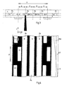
- FIG. 3 shows the coating of a screen detail viewed from above.
- the vertical phosphor stripes Ph in blue B, green G, red R and the black matrix areas BM are arranged between the glass 4 on the front and the aluminum layer 5 on the back, on which the index areas I are located.
- the length of a pixel p extends from the center of an index area I to the center of the following index area I in the X direction, with the phosphor stripes blue B, green G and red R in between and a pixel p divided into four equal distances a becomes. It is also possible to integrate the index areas I into the black matrix areas BM.
- FIG. 4 shows the coating of the screen detail according to FIG. 3 viewed from behind.
- the subdivision of the index areas I can be seen, the index areas I being offset by their width and lying on the same optical axis in the vertical direction.
- the distance between the index areas I is ri, the length yi of an index area I is more than four spot lengths.
- the light spot or spot S generated by the beam is elliptical, the length of the ellipse being extendable.
- the width of the spot must be adapted to the phosphor stripe Ph.
- the spot writes the vertical lines one after the other by first writing over the index areas I, then blue B, green G and red R.
- the index areas are arranged so that if the spot is too far to the left of the vertical direction, the indexes I1 and I3 project more light than index I2 and so that the deviation is measured by the difference in amplitude and readjusted by influencing the beam deflection by the deflection yokes 3.
- the spot hits the area ri between two vertical indexes I, no more light is generated, so that the vertical spot position is detected. Since the image information to be written is located in a memory, if a readjustment based on the index areas has been detected, it is changed accordingly, so that the phosphor stripes blue B, green G and red R are controlled correctly.
Landscapes
- Video Image Reproduction Devices For Color Tv Systems (AREA)
- Telescopes (AREA)
- Cathode-Ray Tubes And Fluorescent Screens For Display (AREA)
Description
- Die Erfindung geht aus von einer Bildröhre gemäß dem Oberbegriff des Anspruchs 1. Es ist bekannt, aus EP 0 356 823 Al, eine große Bildschirmfläche mit einer Bildschirmdiagonalen von ≥ 40" zu schaffen, indem mehrere Kanonen so angeordnet sind, daß eine große Bildschirmfläche mit mehreren Teilbildern dargestellt wird. Bei derartigen Lösungen werden Lochmasken verwendet, die den Wirkungsgrad der Helligkeit erheblich herabsetzen und die Teilbildübergänge erkennen lassen. Die Abweichung des Elektronenstrahls und dessen Helligkeit wird nicht bemerkt und korrigiert.
- Der Erfindung liegt die Aufgabe zugrunde, eine Bildröhre ohne Lochmaske zu schaffen mit einer Vielzahl an Kanonen, bei der die Teilbildübergänge nicht wahrnehmbar sind. Diese Aufgabe wird durch die im Anspruch 1 angegebene Erfindung gelöst. Vorteilhafte Weiterbildungen sind in den Unteransprüchen angegeben.
- Bei der Erfindung werden mehrere Kanonen, je nach Größe des Bildschirms, in vertikaler und horizontaler Richtung nebeneinander angeordnet. Die Innenseite des Bildschirms ist mit blauen, grünen und roten senkrechten Phosphorstreifen beschichtet, und diese sind durch lichtundurchlässigen Streifen vorzugsweise Black Matrix Streifen getrennt. In den Black Matrix Streifen Bereichen befinden sich Index Bereiche, die zur vertikalen und horizontalen Positionsfindung des Strahles dienen. Die in vertikaler Richtung angeordneten Kanonen bilden eine Kolonne, und jede Kolonne hat mindestens einen optischen Sensor, um die Position und die Helligkeit des Strahles festzustellen. Bei Abweichungen wird in horizontaler und vertikaler Richtung nachjustiert und die Helligkeit angepaßt, so daß die Teilbildübergänge nicht zu sehen sind.
- Die einzelnen Kolonnen sind durch optische Wände getrennt, die sich auf der Innenseite des Bildschirms befinden, aber jede Kanone schreibt ihr eigenes Teilbild auf dem Bildschirm. Durch die Aneinanderreihung der Teilbilder ergibt sich auf dem Bildschirm das gesamte Bild, in dem durch die helligkeitskontinuierlichen Übergänge kein Teilbildübergang zu sehen ist.
- Bei der Bildröhre wird keine Lochmaske verwendet, so daß der Heilligkeitswirkungsgrad um den Faktor 4 im Vergleich zum "shadow masc prinzip" erhöht werden kann.
- Im folgendem Beispiel wird die Erfindung anhand der Zeichnung erläutert. Die einzelnen Figuren stellen dar:
- Fig. 1
- den Prinzipbildschirm der erfindungsgemäßen Bildröhre von hinten betrachtet;
- Fig. 2
- den Prinzipbildschirm der erfindungsgemäßen Bildröhre von oben betrachtet;
- Fig. 3
- die Beschichtung eines Bildschirmauschnittes von oben betrachtet und
- Fig. 4
- die Beschichtung eines Bildschirmausschnittes von hinten betrachtet.
- Fig. 1 zeigt einen Bildschirm der Bildröhre, welche mit fünfzehn Monostrahlkanonen K ausgestattet ist. Die Anordnung von drei vertikalen Kanonen K in einer Kolonne und die Aneinanderreihung von fünf Kolonnen in der horizontalen Richtung wurde in Anlehnung an ein darzustellendes Format 16:9 gewählt. Das darzustellende Bild wird von fünfzehn Kanonen K erstellt, die die Teilbilder 1.1 bis 3.5 schreiben. Die Phosphorstreifen blau B, grün G und rot R sind nebeneinander senkrecht angeordnet und durch Black Matrix Streifen BM getrennt. Die senkrechte streifenweise Anordnung der Phosphorstreifen Ph hat zum einen den Vorteil, daß unterschiedliche Zeilenzahlen projiziert werden können, und zum anderen, daß mit den schon erwähnten Monostrahlkanonen K gearbeitet werden kann. Da ein Fernsehbild normalerweise mit horizontalen Zeilen geschrieben wird, aber hier sich das Bild aus vertikal geschriebenen Zeilen zusammensetzt, ist eine Elektronik mit einem Bildspeicher vorzusehen, die das Bild mit den horizontalen Zeilen aufnimmt und in vertikalen Zeilen ausgibt.
- Ein optischer Sensor Opt ist jeweils pro Kolonne in der Mitte angeordnet, um so die Position der einzelnen Strahlen feststellen zu können. Die einzelnen Kolonnen sind durch optische Wände 2 getrennt, wobei am Anfang und am Ende der Kolonne die optische Wand eine Lücke aufweist. Diese Lücke dient dem benachbarten Sensor und dem Sensor der betroffenen Kolonne, damit die optischen Sensoren Opt die Position und die Helligkeit der benachbarten Strahlen wahrnehmen und so eine Anpassung zwischen den Teilbildern vorgenommen wird. Der Strahlverlauf in einer Kolonne ist synchron, so daß die Information über Kolonnenanfang und Kolonnenende vorteilhaft ausgenutzt wird, um die Synchronisation zu überwachen und gegebenenfalls anzupassen. Der abgetastete Bereich aB ist größer als der sichtbare Bereich sB.
- Fig. 2 zeigt die Bildröhre von oben betrachtet, wobei zu erkennen sind der optische Sensor Opt für eine Kolonne, das Ablenkjoch 3 der Bildröhre und die Kanonen K. Es ist zu sehen, daß der darzustellende Winkelbereich einer Kanone gering ist, ca. 40°. Aus diesem Grunde kann die Bildröhre mit einer geringeren Tiefe T auskommen. Die optischen Wände 2 trennen jeweils die Kolonnen voneinander.
- Fig. 3 zeigt die Beschichtung eines Bildschirmausschnittes von oben betrachtet. Zwischen dem Glas 4 der Vorderseite und der Aluschicht 5 auf der Rückseite, auf welcher sich die Index Bereiche I befinden, sind die vertikalen Phosphorstreifen Ph in blau B, grün G, Rot R sowie die Black Matrix Bereiche BM angeordnet. Die Länge eines Pixels p erstreckt sich von der Mitte eines Index Bereiches I bis zu der Mitte des folgenden Indexbereiches I in X-Richtung, wobei die Phosphorstreifen blau B, grün G und rot R dazwischen liegen und ein Pixel p in vier gleiche Abstände a unterteilt wird. Es ist auch möglich, die Indexbereiche I mit in die Blackmatrixbereiche BM zu integrieren.
- Fig. 4 zeigt die Beschichtung des Bildschirmausschnittes gemäß Fig. 3 von hinten betrachtet. In dieser Darstellung ist die Unterteilung der Index Bereiche I zu sehen, wobei die Index Bereiche I um ihre Breite versetzt, in vertikaler Richtung an der gleichen optischen Achse liegen. Der Abstand zwischen den Indexbereichen I ist ri, wobei die Länge yi eines Indexbereiches I mehr als vier Spotlängen beträgt. Der vom Strahl erzeugte Leuchtfleck oder Spot S ist elliptisch, wobei die Länge der Ellipse noch verlängerbar ist. In der Breite muß der Spot jedoch an den Phosphorstreifen Ph angepaßt sein. Der Spot schreibt nacheinander die vertikalen Zeilen, indem er zuerst über die Index Bereiche I schreibt, danach blau B, grün G und rot R. Die Index Bereiche sind so angeordnet, daß, wenn der Spot sich zu sehr links von der vertikalen Richtung befindet, die Indexe I1 und I3 mehr Licht projizieren als Index I2 und daß so, durch den Amplitudenunterschied, die Abweichung gemessen und durch Beeinflussung der Strahlablenkung durch die Ablenkjoche 3 nachjustiert wird. Wenn der Spot den Bereich ri zwischen zwei vertikalen Index I trifft, wird kein Licht mehr erzeugt, so daß die vertikale Spot Position erfaßt wird. Da die zu schreibende Bildinformation sich in einem Speicher befindet, wird dieser, wenn eine Nachjustierung anhand der Indexbereiche erkannt wurde, dementsprechend verändert, so daß die Phosphorstreifen blau B, grün G und rot R richtig angesteuert werden. Für die Darstellung eines Bildes wird weniger Videospeichervolumen benötigt, da die Monostrahlkanone K zwar sehr schnell in vertikaler Richtung die vier Streifen schreibt, aber die benötigte Information ist geringer, als wenn drei Kannonen die jeweiligen Farben schreiben. Bei einer Farbe z.B. grün wird nur diese Information benötigt und die anderen beiden Phosphorstreifen blau B und rot R werden schwarz geschrieben. Die sehr schnelle Schreibweise der einzelnen Streifen wird vorteilhaft verringert, da ja jede Kanone K nur ein Teilbild schreibt.
Claims (10)
- Bildröhre mit einer Vielzahl an Kanonen, wobei jede Kanone ein Teilbild darstellt, so daß sich ein Gesamtbild ohne Teilbildübergänge ergibt, dadurch gekennzeichnet, daß unter Verzicht auf eine Lochmaske die Innenseite des Bildschirms beschichtet ist mit vertikal angeordneten Phosphor-Farbstreifen (Ph), die durch lichtundurchlässige Streifen (BM) voneinander getrennt sind auf denen sich teilweise Index Bereiche (I) zur vertikalen und horizontalen Positionsfindung befinden, wobei die Kanonen als Monostrahlkanonen (K) ausgebildet und in horizontaler und vertikaler Richtung angeordnet sind und den in der Vertikalen liegenden Kanonen (K) mindestens ein optischer Sensor (Opt) zugeordnet ist.
- Bildröhre nach Anspruch 1, dadurch gekennzeichnet, daß für die Positions- und Helligkeitserfassung des Spots Index Bereiche (I) und optische Sensoren (Opt) vorgesehen sind.
- Bildröhre nach Anspruch 1, dadurch gekennzeichnet, daß der Bildschirm mit blau (B), grün (G) und roten (R) senkrechten Phosphorstreifen (Ph) beschichtet ist und diese durch lichtundurchlässige Streifen (BM) vorzugsweise Black Matrix Streifen (BM) getrennt sind.
- Bildröhre nach Anspruch 1, dadurch gekennzeichnet, daß sich auf oder in den lichtundurchlässigen Streifen (BM) Index Bereiche (I) befinden.
- Bildröhre nach Anspruch 1, dadurch gekennzeichnet, daß den senkrecht angeordneten Kanonen (Kolonne) mindestens ein optischer Sensor (Opt) zugeordnet ist.
- Bildröhre nach Anspruch 1, dadurch gekennzeichnet, daß die senkrecht angeordneten Kanonen (Kolonne) durch optische Wände (2) voneinander getrennnt sind.
- Bildröhre nach Anspruch 1, dadurch gekennzeichnet, daß die optischen Wände (2) Lücken aufweisen.
- Bildröhre nach Anspruch 1, dadurch gekennzeichnet, daß die senkrecht angeorneten Kanonen (Kolonne) synchron angesteuert werden.
- Bildröhre nach Anspruch 1, dadurch gekennzeichnet, daß die Kanonen durch senkrecht abgelenkte Strahlen die Teilbilder erstellen.
- Schaltung für eine Bildröhre nach Anspruch 1, dadurch gekennzeichnet, daß ein aus horizontalen Zeilen bestehendes Bild in einem Speicher abgelegt und der Speicher derart ausgelesen wird, daß eine Ausgabe von vertikalen Zeilen erfolgt.
Applications Claiming Priority (2)
| Application Number | Priority Date | Filing Date | Title |
|---|---|---|---|
| DE4240353A DE4240353A1 (de) | 1992-12-01 | 1992-12-01 | Bildröhre mit einer Vielzahl von Kanonen |
| DE4240353 | 1992-12-01 |
Publications (2)
| Publication Number | Publication Date |
|---|---|
| EP0600325A1 EP0600325A1 (de) | 1994-06-08 |
| EP0600325B1 true EP0600325B1 (de) | 1997-03-05 |
Family
ID=6474090
Family Applications (1)
| Application Number | Title | Priority Date | Filing Date |
|---|---|---|---|
| EP93118696A Expired - Lifetime EP0600325B1 (de) | 1992-12-01 | 1993-11-20 | Bildröhre mit einer Vielzahl von Kanonen |
Country Status (5)
| Country | Link |
|---|---|
| US (1) | US5418426A (de) |
| EP (1) | EP0600325B1 (de) |
| JP (1) | JPH06215707A (de) |
| CN (1) | CN1046374C (de) |
| DE (2) | DE4240353A1 (de) |
Families Citing this family (9)
| Publication number | Priority date | Publication date | Assignee | Title |
|---|---|---|---|---|
| MY114546A (en) * | 1995-02-03 | 2002-11-30 | Toshiba Kk | Color cathode-ray tube |
| US6061038A (en) * | 1995-11-21 | 2000-05-09 | Washburn; Clayton A. | Multi-deflection CRT display |
| JPH09306391A (ja) * | 1996-05-21 | 1997-11-28 | Toshiba Corp | インデックス方式カラー受像管 |
| JP3068115B1 (ja) * | 1999-03-17 | 2000-07-24 | ソニー株式会社 | 陰極線管および画像補正方法 |
| TW457510B (en) | 1999-05-21 | 2001-10-01 | Sony Corp | Image control device and method, and image display device |
| TW451247B (en) | 1999-05-25 | 2001-08-21 | Sony Corp | Image control device and method, and image display device |
| JP2001056658A (ja) * | 1999-06-07 | 2001-02-27 | Sony Corp | 陰極線管並びに輝度制御装置および方法 |
| JP3417394B2 (ja) * | 2000-09-13 | 2003-06-16 | ソニー株式会社 | 陰極線管および陰極線管における信号検出方法 |
| CN107728976B (zh) * | 2017-09-22 | 2021-02-09 | 海信视像科技股份有限公司 | 一种画面调节方法及其装置 |
Family Cites Families (12)
| Publication number | Priority date | Publication date | Assignee | Title |
|---|---|---|---|---|
| US3289196A (en) * | 1962-02-19 | 1966-11-29 | Hull Instr Inc | Cathode ray tube display with means for recording the tube display |
| US4225880A (en) * | 1978-11-16 | 1980-09-30 | Goodman David M | Energy-efficient beam-index displays with programmable power supplies |
| DE3006943A1 (de) * | 1980-02-25 | 1981-09-10 | Licentia Patent-Verwaltungs-Gmbh, 6000 Frankfurt | Farbbildwiedergabevorrichtung |
| US4386364A (en) * | 1980-09-12 | 1983-05-31 | Sony Corporation | Image display apparatus |
| SU1021024A1 (ru) * | 1981-01-27 | 1983-05-30 | Предприятие П/Я Г-4937 | Устройство отображени информации на большом экране |
| FR2549671B1 (fr) * | 1983-07-22 | 1987-05-22 | Thomson Csf | Dispositif d'affichage d'une image de television de grandes dimensions et recepteur de television comportant un tel dispositif |
| JPH0746574B2 (ja) * | 1985-05-10 | 1995-05-17 | 株式会社東芝 | 陰極線管装置 |
| JPH0750593B2 (ja) * | 1985-05-10 | 1995-05-31 | 株式会社東芝 | カラ−受像管 |
| DE3678679D1 (de) * | 1985-12-09 | 1991-05-16 | Toshiba Kawasaki Kk | Farbbildroehre. |
| JP2693419B2 (ja) * | 1986-01-22 | 1997-12-24 | 株式会社東芝 | カラー受像装置 |
| JPS62173878A (ja) * | 1986-01-27 | 1987-07-30 | Nec Kansai Ltd | ビ−ムインデツクス形陰極線管装置 |
| EP0356823B1 (de) * | 1988-08-30 | 1993-02-10 | Kabushiki Kaisha Toshiba | Farbkathodenstrahlröhre und Röhrenkolben für Farbkathodenstrahlröhren |
-
1992
- 1992-12-01 DE DE4240353A patent/DE4240353A1/de not_active Withdrawn
-
1993
- 1993-11-12 US US08/150,910 patent/US5418426A/en not_active Expired - Fee Related
- 1993-11-20 DE DE59305608T patent/DE59305608D1/de not_active Expired - Fee Related
- 1993-11-20 EP EP93118696A patent/EP0600325B1/de not_active Expired - Lifetime
- 1993-11-30 CN CN93120700A patent/CN1046374C/zh not_active Expired - Fee Related
- 1993-12-01 JP JP5302035A patent/JPH06215707A/ja active Pending
Also Published As
| Publication number | Publication date |
|---|---|
| EP0600325A1 (de) | 1994-06-08 |
| DE4240353A1 (de) | 1994-06-09 |
| CN1091858A (zh) | 1994-09-07 |
| US5418426A (en) | 1995-05-23 |
| JPH06215707A (ja) | 1994-08-05 |
| DE59305608D1 (de) | 1997-04-10 |
| CN1046374C (zh) | 1999-11-10 |
Similar Documents
| Publication | Publication Date | Title |
|---|---|---|
| DE68921592T2 (de) | Wiedergabevorrichtung. | |
| DE2223818C3 (de) | Selbstkonvergierende Farbbildwiedergabeeinrichtung | |
| EP0600325B1 (de) | Bildröhre mit einer Vielzahl von Kanonen | |
| DE69600022T2 (de) | Farbkathodenstrahlröhre | |
| AT259640B (de) | Farbfernseh-Bildröhre | |
| DE2615569C3 (de) | Farbbildwiedergabevorrichtung | |
| DE942747C (de) | Schaltung fuer eine Fernseh-Wiedergaberoehre | |
| DE3856169T2 (de) | Kathodenstrahlröhre vom Schattenmaskentyp | |
| DE2026412A1 (de) | Schattenmaske für Kathodenstrahlröhren | |
| DE2207632C3 (de) | Verfahren zur optischen Wiedergabe von rasterartig aus Lichtpunkten gebildeten Zeichen auf einer Projektionsfläche | |
| DE69200815T2 (de) | Farbkathodenstrahlröhre. | |
| DD238473A5 (de) | Schlitzmaskenelektronenkanone fuer katodenstrahlroehren | |
| DE2619871A1 (de) | Kathodenstrahlroehre mit verbesserter schirmstruktur | |
| DE3043048C2 (de) | ||
| DE1487095A1 (de) | Kathodenstrahlroehre,insbesondere Fernseh-Bildroehre | |
| DE69029213T2 (de) | CRT-Matrixtyp-Videosichtgerät | |
| DE2813386A1 (de) | Einzeilen-elektronenrohranordnung | |
| DE667405C (de) | Anordnung zur Regelung der wirksamen Elektronendurchtrittsoeffnung fuer eine Bildzerlegerroehre | |
| DE69304802T2 (de) | Flache Bildwiedergabeanordnung mit Elektronenfortpflanzungskanälen | |
| EP0062281B1 (de) | Verfahren und Vorrichtung zur Ermittlung der Farbreinheits- und der Konvergenzkorrekturgrösse auf einem Farbfernseh-Bildschirm vom In-Line-Typ mit magnetischen Ablenkmitteln | |
| DE4143199C2 (de) | Elektronenkanone für eine Kathodenstrahlröhre | |
| EP0975003A1 (de) | Farbfernsehgerät oder Farbmonitor mit flachem Bildschirm | |
| DE1462481C3 (de) | Farbfernsehbildröhre | |
| DE2346854C3 (de) | Ablenkspulensatz für Farbfernsehen | |
| DE2935856A1 (de) | Kathodenstrahlroehre mit schattenmaske |
Legal Events
| Date | Code | Title | Description |
|---|---|---|---|
| PUAI | Public reference made under article 153(3) epc to a published international application that has entered the european phase |
Free format text: ORIGINAL CODE: 0009012 |
|
| AK | Designated contracting states |
Kind code of ref document: A1 Designated state(s): DE FR GB IT |
|
| 17P | Request for examination filed |
Effective date: 19941025 |
|
| 17Q | First examination report despatched |
Effective date: 19950712 |
|
| GRAG | Despatch of communication of intention to grant |
Free format text: ORIGINAL CODE: EPIDOS AGRA |
|
| GRAH | Despatch of communication of intention to grant a patent |
Free format text: ORIGINAL CODE: EPIDOS IGRA |
|
| GRAH | Despatch of communication of intention to grant a patent |
Free format text: ORIGINAL CODE: EPIDOS IGRA |
|
| GRAA | (expected) grant |
Free format text: ORIGINAL CODE: 0009210 |
|
| GRAH | Despatch of communication of intention to grant a patent |
Free format text: ORIGINAL CODE: EPIDOS IGRA |
|
| ITF | It: translation for a ep patent filed | ||
| AK | Designated contracting states |
Kind code of ref document: B1 Designated state(s): DE FR GB IT |
|
| REF | Corresponds to: |
Ref document number: 59305608 Country of ref document: DE Date of ref document: 19970410 |
|
| ET | Fr: translation filed | ||
| GBT | Gb: translation of ep patent filed (gb section 77(6)(a)/1977) |
Effective date: 19970512 |
|
| PLBE | No opposition filed within time limit |
Free format text: ORIGINAL CODE: 0009261 |
|
| STAA | Information on the status of an ep patent application or granted ep patent |
Free format text: STATUS: NO OPPOSITION FILED WITHIN TIME LIMIT |
|
| 26N | No opposition filed | ||
| PGFP | Annual fee paid to national office [announced via postgrant information from national office to epo] |
Ref country code: GB Payment date: 19991018 Year of fee payment: 7 |
|
| PGFP | Annual fee paid to national office [announced via postgrant information from national office to epo] |
Ref country code: FR Payment date: 19991123 Year of fee payment: 7 |
|
| PGFP | Annual fee paid to national office [announced via postgrant information from national office to epo] |
Ref country code: DE Payment date: 19991229 Year of fee payment: 8 |
|
| PG25 | Lapsed in a contracting state [announced via postgrant information from national office to epo] |
Ref country code: GB Free format text: LAPSE BECAUSE OF NON-PAYMENT OF DUE FEES Effective date: 20001120 |
|
| GBPC | Gb: european patent ceased through non-payment of renewal fee |
Effective date: 20001120 |
|
| PG25 | Lapsed in a contracting state [announced via postgrant information from national office to epo] |
Ref country code: FR Free format text: LAPSE BECAUSE OF NON-PAYMENT OF DUE FEES Effective date: 20010731 |
|
| REG | Reference to a national code |
Ref country code: FR Ref legal event code: ST |
|
| PG25 | Lapsed in a contracting state [announced via postgrant information from national office to epo] |
Ref country code: DE Free format text: LAPSE BECAUSE OF NON-PAYMENT OF DUE FEES Effective date: 20020702 |
|
| PG25 | Lapsed in a contracting state [announced via postgrant information from national office to epo] |
Ref country code: IT Free format text: LAPSE BECAUSE OF NON-PAYMENT OF DUE FEES;WARNING: LAPSES OF ITALIAN PATENTS WITH EFFECTIVE DATE BEFORE 2007 MAY HAVE OCCURRED AT ANY TIME BEFORE 2007. THE CORRECT EFFECTIVE DATE MAY BE DIFFERENT FROM THE ONE RECORDED. Effective date: 20051120 |