EP0599110B1 - Machines à laver le linge et la vaisselle avec distributeur de détergent amélioré - Google Patents
Machines à laver le linge et la vaisselle avec distributeur de détergent amélioré Download PDFInfo
- Publication number
- EP0599110B1 EP0599110B1 EP93117902A EP93117902A EP0599110B1 EP 0599110 B1 EP0599110 B1 EP 0599110B1 EP 93117902 A EP93117902 A EP 93117902A EP 93117902 A EP93117902 A EP 93117902A EP 0599110 B1 EP0599110 B1 EP 0599110B1
- Authority
- EP
- European Patent Office
- Prior art keywords
- washing
- washing machine
- machine according
- storage container
- appropriate
- Prior art date
- Legal status (The legal status is an assumption and is not a legal conclusion. Google has not performed a legal analysis and makes no representation as to the accuracy of the status listed.)
- Expired - Lifetime
Links
- 238000005406 washing Methods 0.000 title claims description 64
- 239000003599 detergent Substances 0.000 title description 43
- 238000003860 storage Methods 0.000 claims description 39
- 239000000843 powder Substances 0.000 claims description 22
- XLYOFNOQVPJJNP-UHFFFAOYSA-N water Substances O XLYOFNOQVPJJNP-UHFFFAOYSA-N 0.000 claims description 8
- 238000010276 construction Methods 0.000 claims description 5
- 239000003795 chemical substances by application Substances 0.000 claims 8
- 238000005192 partition Methods 0.000 claims 2
- 230000004075 alteration Effects 0.000 claims 1
- 230000005540 biological transmission Effects 0.000 claims 1
- 239000000126 substance Substances 0.000 description 8
- 238000000034 method Methods 0.000 description 5
- 230000015572 biosynthetic process Effects 0.000 description 4
- 230000005484 gravity Effects 0.000 description 4
- 238000010412 laundry washing Methods 0.000 description 4
- 230000000694 effects Effects 0.000 description 2
- 230000000149 penetrating effect Effects 0.000 description 2
- 239000012459 cleaning agent Substances 0.000 description 1
- 230000006835 compression Effects 0.000 description 1
- 238000007906 compression Methods 0.000 description 1
- 238000005520 cutting process Methods 0.000 description 1
- 238000004851 dishwashing Methods 0.000 description 1
- 239000003344 environmental pollutant Substances 0.000 description 1
- 239000004744 fabric Substances 0.000 description 1
- 238000005429 filling process Methods 0.000 description 1
- 238000004519 manufacturing process Methods 0.000 description 1
- 231100000719 pollutant Toxicity 0.000 description 1
- 238000000926 separation method Methods 0.000 description 1
- 238000003756 stirring Methods 0.000 description 1
Images


Classifications
-
- A—HUMAN NECESSITIES
- A47—FURNITURE; DOMESTIC ARTICLES OR APPLIANCES; COFFEE MILLS; SPICE MILLS; SUCTION CLEANERS IN GENERAL
- A47L—DOMESTIC WASHING OR CLEANING; SUCTION CLEANERS IN GENERAL
- A47L15/00—Washing or rinsing machines for crockery or tableware
- A47L15/42—Details
- A47L15/44—Devices for adding cleaning agents; Devices for dispensing cleaning agents, rinsing aids or deodorants
- A47L15/4463—Multi-dose dispensing arrangements
-
- D—TEXTILES; PAPER
- D06—TREATMENT OF TEXTILES OR THE LIKE; LAUNDERING; FLEXIBLE MATERIALS NOT OTHERWISE PROVIDED FOR
- D06F—LAUNDERING, DRYING, IRONING, PRESSING OR FOLDING TEXTILE ARTICLES
- D06F39/00—Details of washing machines not specific to a single type of machines covered by groups D06F9/00 - D06F27/00
- D06F39/02—Devices for adding soap or other washing agents
- D06F39/026—Devices for adding soap or other washing agents the powder or tablets being added directly, e.g. without the need of a flushing liquid
Definitions
- the invention relates to washing machines and dishwashers, particularly for the household, with an improved distributor in order to facilitate the filling and dosing of the cleaning agent in powder form and other substances in powder form which are used in these washing machines and dishwashers.
- This invention applies to any washing and dishwashing machine, be it for crockery or for fabric parts, for which substances are used in powder form, but it is clear that the most advantageous application takes place in laundry washing machines. Therefore, in the course of the description reference is made to a front loading laundry washing machine, it being assumed that the described and claimed with the obvious expedient changes also apply to laundry washing machines for loading from above and for dishwashers.
- Laundry washing machines with a drawer which can be pulled out from the outside are known, the drawer mentioned having a plurality of sub-compartments into which the washing powder and the other substances which are used in the various phases of the washing cycle are filled.
- the drawer is closed again after it has been filled and the washing cycle begins, which, between the various processes which take place by means of various circuits and devices which are not described in any more detail and which are known in the prior art, provides for a water jet to selectively trickle down over the sub-compartments mentioned, and these Substances in powder form are washed away and gravity-fed into the washing container.
- This occurrence of lump formation is based on three basic causes: the first reason is that these lumps already exist in the original container and are only transferred to the machine's storage container; the second reason is that the relatively large amount of detergent, which can also be stored for a long time, exerts pressure on the lower layers of the supply, which also causes the formation of lumps by the natural adhesion and compressibility of the washing powder; the third reason, which favors the two previously mentioned, is due to the increased moisture generated by the washing machine and slowly entering the storage container, which greatly increases the formation and hardening of the lumps.
- the detergent When the detergent is dosed automatically one after the other, it is poured into the above-mentioned shaft, but existing hard lumps quickly block the above-mentioned shaft and therefore impede any kind of controlled removal of the detergent.
- the filling process which is carried out by the user, is currently subject to errors in the metering and in particular in the intentional overdosing, which occurs in the unclear belief that a larger amount of detergent results in better washing quality.
- the generic US-A-25 98 227 is known.
- This document discloses a metering device for powdery substances, in which the powdery substances are stored in a storage container.
- the metering device has an agitator with which the powder is fed to a drum of a washing machine with the screw screw arranged at an outlet. With this agitator, lump formation, particularly in the edge area of the storage container, cannot be avoided.
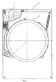
- the figures show a section of a washing machine, consisting of a washing container 1, a work surface 2, a storage container 3 for washing powder, a lid 4 for said storage container, a funnel 5, which is arranged on the bottom of said storage container and is suitable by gravity to feed detergent dispenser 6 arranged below it.
- the storage container 3 contains a plurality of movable elements 7 for crushing the lumps of detergent, the said movable elements preferably being wheels similar to the cutting wheels, each of which is cylindrical in shape and provided with a plurality of outer arms 8 and radial arms 9 which hold the said outer arms 8 and transfer the motion to it.
- the said movable elements are preferably arranged with axes running parallel to one another and are paired with one another in such a way that their axes are at a distance from one another which is smaller than the length of the radial arms 9.
- Said movable elements can rotate, and upon rotation the outer arms of each pair of elements engage in one another, engaging with one another like a pair of gearwheels which transmit the movement to one another, in such a way that all said movable elements move simultaneously and synchronously.
- the rotary movement is transmitted from a suitable drive device 10, which is arranged outside the storage container, to one of these movable elements, which also transfers the rotation to the others.
- Said drive device can exist in different functional configurations: for example it can be an electric motor which is connected to the axis of a certain movable element which also transfers the rotary movement to the other movable elements; or it can also be an electric motor which acts on suitable gears which are connected to the axes of the said movable elements, which in this case move autonomously and are not carried along by a certain element; or it can also be a simple electric rotary actuator which acts with its adjusting arm on a gear wheel which is connected to one of the movable elements; or it can also be a device that is connected to other rotary components of the washing machine, such as. B. the rotary motor of the drum, and which transmits the rotary movement, possibly via suitable deflections, to an axis of a specific movable element.
- the above-mentioned movable elements can take on a wide variety of shapes and arrangements if they are only able to perform their function effectively, which consists in stirring the lumps of detergent and thus to shred.
- You can e.g. B. have the form of rotating brushes in which the radial elements rotate in different planes so as not to interfere with each other, or they consist of real wheels 12 which are provided with a plurality of closed wings 13.
- the torque required for their movement must be greater, but this can easily be achieved with suitable reduction gears between the drive device 10 and the axes of rotation of the said vanes.
- the said movable elements are at least partially arranged in the vicinity of the inlet opening 14 of the funnel 5, as shown in FIG. 1A.
- a hinged lid 4 is provided in the working surface of the washing machine, through which the user can fill the washing powder into the storage container described.
- a network with sufficiently narrow meshes or a stiff filter element 16 with sufficiently small holes is advantageously arranged in the area of the feed opening of the aforementioned storage container, so that when the detergent is filled in, the user himself intervenes and crushes possible lumps and crushes them into powder, which is therefore can easily pass through said filter element 16.
- the washing machine is to be built over with another body, for example with a tumble dryer, as is increasingly the case, the detergent can of course no longer be filled in from above.
- Figures 5 and 5A show a drawer with a handle 51 and a flat bottom 52, on which a structure 53 is arranged, which forms sub-compartments and is open at the top and bottom, said structure under the action of the horizontal pressure caused by a suitable element 54 is exerted, slides horizontally on said plane in order to penetrate over the storage container, and is held above suitable by drawer guides 55 which prevent it from falling down.
- the method of operation is as follows: the user pulls out the drawer 52, which contains said sub-compartment construction, fills the washing powder into the sub-compartments and, by acting on said element 54, only presses the construction 53 and not the drawer inside.
- the sub-compartments, which are open on the floor, continue to reach the space above the storage container 3 and let the detergent drain into it, then the construction 54 is pulled out again and the procedure described can be repeated until the storage container is filled.
- 6 shows another way of filling the storage container: in this case, the drawer consists of several elements 61 which are shaped as sub-compartments, are telescopically connected and end at the handle 62.
- the user opens when the handle 62 is pulled out the various elements 61 up to their maximum capacity; the detergent is poured onto the container, which consists of all the above elements, and the handle is inserted. In this way, the elements are telescopically pushed into one another, their total internal volume being significantly reduced, and the amount of detergent reduced by this closing process is thereby poured into the storage container.
- FIG. 7 shows another version of a detergent filling device:
- a handle 70 is connected in an articulated manner to an open fork 71 which holds a bellows 72, the lower edges of which close the vertical detergent supply opening 74.
- the user simply lifts the handle 70 mentioned, which in turn lifts the fork 71, which extends and takes the bellows 72 with it.
- the washing powder filled into the horizontal opening 75 slips on the bellows and falls through the vertical feed opening 74 into the storage container.
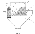
- FIGS. 11 and 11A A particularly effective and functional of these variants is shown in FIGS. 11 and 11A;
- the filling compartment 110 for washing powder has an open bottom, but which can be closed by a plurality of adjoining bulkheads 111, which can rotate about respective horizontal axes.
- the aforementioned bulkheads are articulated on a single arm 112, to which a further inner bulkhead 113 is articulated, the rear end 114 of which is provided with mutually aligned and rotatable guide means, e.g. B. two small hooks 115 and 116.
- the hooks mentioned are inserted in a fixed horizontal guide 117 which is arranged in the direction from front to back and ends in a downward curvature 118 at the rear.
- the spatial arrangement of the components is such that, when the drawer is opened, the bulkheads are rotated so that they lie essentially in the horizontal plane and thus together form a closed bottom of the drawer onto which the washing powder is filled .
- a useful improvement of the invention is to provide the user with the ability to be notified when the detergent fill is running low, ie when the reservoir needs to be refilled. This is particularly useful in view of the fact that after a certain period of use, the average user will no longer get the detergent into the machine every time they are washed to fill and therefore not knowing when this will end.
- the improvement is to provide a weight sensor located below and outside of the reservoir, as shown in FIG. 8.
- the storage container 3 is supported by one or more springs 81 which rest on a support 82 which is fastened to the housing of the machine (not shown).
- the storage container is therefore not rigidly connected to the machine, but rather is inserted into a container or vertical guides 83 which allow it to move slightly vertically, depending on the opposing forces of its weight with the detergent filling contained therein and the upward thrust caused by the aforementioned Springs 81, which are compression springs.
- An arm 88 is actuated beneath said storage container, which actuates a microswitch 85, whereby, after suitable adjustment of the various elements, the storage container rises more and more when it is emptied, until, when empty, it is raised to a point at which said arm 88 triggers microswitch 85.
- this switch operates in two different ways: it turns on an outside light and / or audible indicator that warns the user that the reservoir is empty, and it operates the machine control circuit by disabling its operation until the Storage container is filled with detergent again.
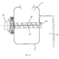
- a special type of metering device for the washing powder is therefore proposed which is significantly less susceptible to the ingress of moisture, the device mentioned being designed as described below with reference to FIG. 9: instead of feeding an opening below by falling, through which the detergent enters the washing container, the detergent storage container 3 feeds an underlying recess 90 which contains a screw 91 which can be rotated about a horizontal axis and whose outlet end 92 abuts an essentially vertical line 93. Said screw is rotated by a suitable small motor 94, the function of which can typically be controlled by the programming of the washing machine.
- the possibly penetrating moisture does not prevent the powder, even if it is slightly moistened, from still being able to be fed into the washing container, since the metering and the separation of the powder are no longer effected by gravity but by the rotational movement of the coils of said screw takes place, which "cut off" the exact amount of powder required and at the same time, by separating it from the rest of the powder, feeds it into said line 93 and from there into the washing container.
- a variant of the device just illustrated, to which FIG. 10 relates, is to replace the small motor 94 for driving the screw with a mill 100 which is driven by a water flow which flows from a suitable line 101 onto the blades the mill mentioned is directed, and wherein the rotary shaft of the mill, possibly via suitable gear, preferably reduction gear, is connected to the rotary shaft of the screw.
- the amount of detergent to be added to each cycle depends on the number of rotations of the screw and thus on the number of rotations of the mill mentioned and ultimately on the amount of water used, which can be controlled by opening the aforementioned electrovalve for a suitable period of time .
Landscapes
- Engineering & Computer Science (AREA)
- Textile Engineering (AREA)
- Detail Structures Of Washing Machines And Dryers (AREA)
Claims (15)
- Machine à laver et rincer, en particulier pour usage domestique, constituée d'une cuve de lavage (1), d'un récipient de réserve (3) pour de la poudre à laver, d'un doseur (6) pour ce détergent, d'une ouverture d'entrée (14) dans ce doseur, d'une conduite qui relie ce doseur à ladite cuve de lavage, le récipient de réserve (3) contenant plusieurs quantités de dosage de détergent, qui peuvent délivrer à la machine le détergent nécessaire lors de plusieurs cycles de lavage successifs, et le détergent étant mélangé périodiquement par plusieurs éléments mobiles (7) dans ledit récipient de réserve, caractérisée en ce que lesdits éléments mobiles sont disposés avec leurs axes parallèles les uns aux autres et s'engagent de telle manière les uns dans les autres que leurs axes se trouvent à une distance les uns des autres qui est inférieure à la longueur des bras radiaux (9), lesdits éléments mobiles peuvent tourner, et en ce que, lors de la rotation, les bras extérieurs (9) de chaque paire d'éléments s'engagent les uns dans les autres, en se transmettant mutuellement le mouvement.
- Machine à laver selon la revendication 1, caractérisée en ce que lesdits éléments mobiles sont formés de roues (12) qui sont munies de plusieurs ailettes fermées (13).
- Machine à laver selon la revendication 1 ou 2, caractérisée en ce que lesdits éléments mobiles (7) sont actionnés par un dispositif d'entraînement approprié (10).
- Machine à laver selon la revendication 3, caractérisée en ce que ledit dispositif d'entraînement (10) est un moteur, qui est relié à l'axe d'un élément mobile déterminé, ou en ce que qu'il est un moteur qui agit sur des engrenages appropriés, qui sont reliés aux axes desdits éléments mobiles, ou en ce qu'il est un actuateur rotatif électrique, qui agit avec son bras sur une roue dentée qui est reliée à l'axe des éléments rotatifs.
- Machine à laver selon la revendication 3 ou 4, caractérisée en ce qu'entre ledit dispositif d'entraînement (10) et lesdits éléments mobiles (7) est placé un boîtier réducteur.
- Machine à laver selon l'une des revendications précédentes, caractérisée en ce qu'il est formé dans le plan de travail un couvercle de fermeture (4) à travers lequel ledit récipient de réserve (3) est accessible.
- Machine à laver selon la revendication 6, caractérisée en ce qu'au niveau de l'ouverture d'introduction dudit récipient de réserve se trouve un grillage ou un élément filtrant (16) avec des trous.
- Machine à laver selon l'une des revendications 1 à 7, caractérisée en ce qu'elle est équipée d'un tiroir qui, par des guides-tiroirs (55) appropriés, est tenu en suspension au-dessus dudit récipient de réserve (3) et est muni d'une poignée (51) ainsi qu'un fond plan (52), sur lequel est placée une construction (53) qui glisse horizontalement sur ledit plan, forme des compartiments, est ouverte vers le haut et vers le bas et est reliée à un élément approprié (54) pour pousser ladite construction.
- Machine à laver selon l'une des revendications 1 à 7, caractérisée en ce qu'elle est équipée d'un tiroir qui est constitué de plusieurs éléments (61), qui sont formés en compartiments, sont reliés de manière télescopique et se terminent par une poignée (62).
- Machine à laver selon l'une des revendications 1 à 7, caractérisée en ce qu'elle est équipée d'une poignée (70) qui est reliée de manière articulée à une fourche ouverte (71), qui entoure l'ouverture d'introduction horizontale (75) pour le détergent et tient un soufflet (72) qui peut être fermé autour de l'ouverture d'introduction verticale de détergent (74).
- Machine à laver selon l'une des revendications 1 à 7, caractérisée en ce qu'elle est équipée d'un tiroir (110) pour le remplissage du détergent, qui a un fond ouvert, mais qui peut être fermé par plusieurs cloisons étanches contiguës (111), qui peuvent tourner autour d'axes horizontaux respectifs et sont articulés sur un seul bras (112), sur lequel est articulée également une cloison intérieure (113) dont l'extrémité arrière (114) est munie de moyens de guidage (115, 116) mutuellement alignés et rotatifs, lesdits moyens étant insérés dans un guidage horizontal (117) qui est disposé dans la direction d'avant en arrière et se termine à l'arrière par une courbure (118).
- Machine à laver selon l'une quelconque des revendications précédentes, caractérisée en ce que le récipient de réserve (3) est soutenu par plusieurs ressorts (81) qui reposent sur un support (82), lequel est fixé au boîtier de la machine, ledit récipient de réserve étant inséré dans un récipient avec des guidages verticaux (83), dont le fond forme une surface de contrôle pour la position dudit récipient de réserve, surface contre laquelle s'appuie un bras (88) qui actionne un commutateur (85) approprié, lequel peut afficher à l'extérieur les modifications de position dudit récipient de réserve.
- Machine à laver selon l'une quelconque des revendications précédentes, caractérisée en ce que le récipient de réserve de détergent (3) alimente un évidement placé en bas (90), qui contient une vis sans fin (91) rotative autour d'un axe horizontal, vis dont l'extrémité extérieure (92) bute dans une conduite (93) pour l'essentiel verticale, ladite vis sans fin étant mise en mouvement de rotation par un moteur (94) approprié dont le fonctionnement peut être commandé par la programmation de la machine.
- Machine à laver selon la revendication 13, caractérisée en ce que le moteur (94) d'entraînement de la vis sans fin est remplacé par un moulin (100) qui est entraîné par un courant d'eau provenant d'une conduite (101) appropriée, l'arbre rotatif du moulin étant relié à l'arbre rotatif de la vis sans fin, éventuellement par l'intermédiaire de moyens de transmission appropriés.
- Machine selon la revendication 14, caractérisée en ce que ladite conduite (101) provient d'une dérivation de la conduite d'alimentation principale de la machine, grâce à une vanne de fermeture pilotable appropriée.
Applications Claiming Priority (2)
| Application Number | Priority Date | Filing Date | Title |
|---|---|---|---|
| ITPN920088A IT1259236B (it) | 1992-11-27 | 1992-11-27 | Macchine per il lavaggio con distributore di detersivo perfezionato. |
| ITPN920088 | 1992-11-27 |
Publications (2)
| Publication Number | Publication Date |
|---|---|
| EP0599110A1 EP0599110A1 (fr) | 1994-06-01 |
| EP0599110B1 true EP0599110B1 (fr) | 1997-02-12 |
Family
ID=11394727
Family Applications (1)
| Application Number | Title | Priority Date | Filing Date |
|---|---|---|---|
| EP93117902A Expired - Lifetime EP0599110B1 (fr) | 1992-11-27 | 1993-11-04 | Machines à laver le linge et la vaisselle avec distributeur de détergent amélioré |
Country Status (4)
| Country | Link |
|---|---|
| EP (1) | EP0599110B1 (fr) |
| DE (1) | DE59305448D1 (fr) |
| ES (1) | ES2097422T3 (fr) |
| IT (1) | IT1259236B (fr) |
Cited By (2)
| Publication number | Priority date | Publication date | Assignee | Title |
|---|---|---|---|---|
| US7754025B1 (en) | 2000-06-08 | 2010-07-13 | Beverage Works, Inc. | Dishwasher having a door supply housing which holds dish washing supply for multiple wash cycles |
| US8190290B2 (en) | 2000-06-08 | 2012-05-29 | Beverage Works, Inc. | Appliance with dispenser |
Families Citing this family (9)
| Publication number | Priority date | Publication date | Assignee | Title |
|---|---|---|---|---|
| DE19740819A1 (de) * | 1997-09-17 | 1999-03-18 | Ako Werke Gmbh & Co | Vorrichtung zum dosierten Zugeben eines pulverförmigen Reinigungsmittels in wasserführenden Reinigungsmaschinen |
| WO2003027377A1 (fr) * | 2001-09-12 | 2003-04-03 | Cading Konstruktions Gmbh Für Maschinenbau | Dispositif doseur de reservoir permettant de d'approvisionner et de doser des detergents liquides dans des appareils menagers |
| WO2003044256A1 (fr) * | 2001-11-08 | 2003-05-30 | Arçelik A. S. | Appareil electromenager |
| KR100446493B1 (ko) * | 2002-07-26 | 2004-09-01 | 삼성전자주식회사 | 세탁기 |
| DE102004045446A1 (de) * | 2004-09-18 | 2006-03-23 | Premark Feg L.L.C., Wilmington | Geschirrspülmaschine mit mindestens einer Versorgungseinrichtung zur Bereitstellung eines Spülzusatzes |
| IT1390915B1 (it) * | 2008-07-24 | 2011-10-19 | Indesit Co Spa | Macchina di lavaggio comprendente un cassetto di caricamento per agenti di lavaggio |
| CN113818212B (zh) * | 2020-06-19 | 2024-08-27 | 青岛海尔洗衣机有限公司 | 一种洗涤剂盒组件及洗衣机 |
| CN113818214B (zh) * | 2020-06-19 | 2024-07-16 | 青岛海尔洗衣机有限公司 | 一种洗涤剂溶解装置及洗衣机 |
| CN113818213B (zh) * | 2020-06-19 | 2024-03-01 | 青岛海尔洗衣机有限公司 | 一种洗涤剂盒及洗衣机 |
Family Cites Families (5)
| Publication number | Priority date | Publication date | Assignee | Title |
|---|---|---|---|---|
| US2514000A (en) * | 1945-08-20 | 1950-07-04 | Sophia Tank | Dishwashing apparatus |
| US2598227A (en) * | 1948-03-12 | 1952-05-27 | Avco Mfg Corp | Injector for powdered materials |
| DE2501969C3 (de) * | 1975-01-18 | 1987-10-22 | Licentia Patent-Verwaltungs-Gmbh, 6000 Frankfurt | Anordnung zur Steuerung von Wasch- und Geschirrspülmaschinen |
| CN1003659B (zh) * | 1986-02-06 | 1989-03-22 | 株式会社东芝 | 洗衣机等的洗涤剂供给装置 |
| DE3721381A1 (de) * | 1987-06-29 | 1989-01-19 | Henkel Kgaa | Pulverdosiervorrichtung |
-
1992
- 1992-11-27 IT ITPN920088A patent/IT1259236B/it active IP Right Grant
-
1993
- 1993-11-04 DE DE59305448T patent/DE59305448D1/de not_active Expired - Fee Related
- 1993-11-04 ES ES93117902T patent/ES2097422T3/es not_active Expired - Lifetime
- 1993-11-04 EP EP93117902A patent/EP0599110B1/fr not_active Expired - Lifetime
Cited By (12)
| Publication number | Priority date | Publication date | Assignee | Title |
|---|---|---|---|---|
| US7754025B1 (en) | 2000-06-08 | 2010-07-13 | Beverage Works, Inc. | Dishwasher having a door supply housing which holds dish washing supply for multiple wash cycles |
| US8103378B2 (en) | 2000-06-08 | 2012-01-24 | Beverage Works, Inc. | Appliance having a user interface panel and a beverage dispenser |
| US8190290B2 (en) | 2000-06-08 | 2012-05-29 | Beverage Works, Inc. | Appliance with dispenser |
| US8290615B2 (en) | 2000-06-08 | 2012-10-16 | Beverage Works, Inc. | Appliance with dispenser |
| US8290616B2 (en) | 2000-06-08 | 2012-10-16 | Beverage Works, Inc. | Appliance having a user interface panel and a beverage dispenser |
| US8548624B2 (en) | 2000-06-08 | 2013-10-01 | Beverage Works, Inc. | Appliance having a user interface panel and a beverage dispenser |
| US8565917B2 (en) | 2000-06-08 | 2013-10-22 | Beverage Works, Inc. | Appliance with dispenser |
| US8606395B2 (en) | 2000-06-08 | 2013-12-10 | Beverage Works, Inc. | Appliance having a user interface panel and a beverage dispenser |
| US9090449B2 (en) | 2000-06-08 | 2015-07-28 | Beverage Works, Inc. | Appliance having a user interface panel and a beverage dispenser |
| US9090446B2 (en) | 2000-06-08 | 2015-07-28 | Beverage Works, Inc. | Appliance with dispenser |
| US9090448B2 (en) | 2000-06-08 | 2015-07-28 | Beverage Works, Inc. | Appliance having a user interface panel and a beverage dispenser |
| US9090447B2 (en) | 2000-06-08 | 2015-07-28 | Beverage Works, Inc. | Appliance having a user interface panel and a beverage dispenser |
Also Published As
| Publication number | Publication date |
|---|---|
| ES2097422T3 (es) | 1997-04-01 |
| IT1259236B (it) | 1996-03-11 |
| ITPN920088A0 (it) | 1992-11-27 |
| DE59305448D1 (de) | 1997-03-27 |
| EP0599110A1 (fr) | 1994-06-01 |
| ITPN920088A1 (it) | 1994-05-27 |
Similar Documents
| Publication | Publication Date | Title |
|---|---|---|
| DE69316482T2 (de) | Geschirrspülmaschine | |
| EP0906747A2 (fr) | Dispositif pour la distribution dosée d'un produit de nettoyage en poudre dans les machines à nettoyer utilisant de l'eau | |
| DE69413064T2 (de) | Automatische dosiervorrichtung für mahlgut | |
| EP0599110B1 (fr) | Machines à laver le linge et la vaisselle avec distributeur de détergent amélioré | |
| DE10059183A1 (de) | Getränkemaschine | |
| DE102007037883A1 (de) | Mehrfachzugabeventil für eine Anlage zum Dosieren flüssigen oder pastösen Waschhilfsmitteln und Verfahren zum Betreiben des Mehrfachzugabeventils | |
| EP3468440B1 (fr) | Dispositif de dosage pour des corps moulés de détergent dans des lave-vaisselle ménagers | |
| DE2108031A1 (de) | Eisabgabevorrichtung fur Eiswürfel und zerkleinertes Eis | |
| EP3660198A1 (fr) | Lave-linge pour sous-vêtements et son procédé de fonctionnement | |
| WO2009021874A1 (fr) | Soupape d'addition multiple pour un dispositif de dosage d'auxiliaires de lavage liquides ou pâteux | |
| DE1812654B2 (de) | Vorrichtung zum automatischen zubereiten von kaffee | |
| DE69008302T2 (de) | Einstückige Mahlvorrichtung, insbesondere zum Mahlen einer oder mehrerer Kaffeesorten. | |
| EP3629880A1 (fr) | Lave-vaisselle comportant un dispositif de dosage | |
| DE2006930A1 (de) | Maschine zur Zubereitung von Aufgußgetränken, insbesondere von Espresso-Kaffee | |
| DE60202387T2 (de) | Abgabevorrichtung für Geschirrspülmaschine oder Waschmaschine | |
| DE19848370B4 (de) | Vorrichtung und Verfahren zur Zubereitung eines Kaffeeaufgusses | |
| DE19545773A1 (de) | Vorrichtung für die Einspeisung eines Reinigungsmittels und eines Nachspülmittels in eine Geschirrspülmaschine | |
| DE3730405A1 (de) | Waschmittel-einspueler, insbesondere fuer waschmaschinen | |
| DE102018214652A1 (de) | Geschirrspülmaschine, Verfahren zum Betreiben einer Geschirrspülmaschine und Computerprogrammprodukt | |
| DE29922439U1 (de) | Trockner mit drehender Trommel | |
| EP3468439A1 (fr) | Dispositif de dosage pour corps moulés de produit de nettoyage dans des lave-vaisselles ménagers | |
| DE102017110303A1 (de) | Reinigungsvorrichtung für ein Gargerät | |
| DE19535153B4 (de) | Vorrichtung zur Einspeisung von Spülmitteln für Geschirrspülmaschinen | |
| DE69421452T2 (de) | Obenbeschickbare Waschmaschine mit einer in dem Deckel eingebauten Waschmittelabgabevorrichtung | |
| DE102017208013A1 (de) | Dosiervorrichtung für Reinigungsmittel-Formkörper für eine Geschirrspülmaschine, Geschirrspülmaschine und Verfahren zum Betreiben einer Geschirrspülmaschine |
Legal Events
| Date | Code | Title | Description |
|---|---|---|---|
| PUAI | Public reference made under article 153(3) epc to a published international application that has entered the european phase |
Free format text: ORIGINAL CODE: 0009012 |
|
| AK | Designated contracting states |
Kind code of ref document: A1 Designated state(s): DE ES FR GB IT |
|
| 17P | Request for examination filed |
Effective date: 19940511 |
|
| 17Q | First examination report despatched |
Effective date: 19951222 |
|
| GRAG | Despatch of communication of intention to grant |
Free format text: ORIGINAL CODE: EPIDOS AGRA |
|
| RAP1 | Party data changed (applicant data changed or rights of an application transferred) |
Owner name: ELECTROLUX ZANUSSI ELETTRODOMESTICI S.P.A. |
|
| GRAH | Despatch of communication of intention to grant a patent |
Free format text: ORIGINAL CODE: EPIDOS IGRA |
|
| GRAH | Despatch of communication of intention to grant a patent |
Free format text: ORIGINAL CODE: EPIDOS IGRA |
|
| ITF | It: translation for a ep patent filed | ||
| GRAA | (expected) grant |
Free format text: ORIGINAL CODE: 0009210 |
|
| AK | Designated contracting states |
Kind code of ref document: B1 Designated state(s): DE ES FR GB IT |
|
| GBT | Gb: translation of ep patent filed (gb section 77(6)(a)/1977) |
Effective date: 19970214 |
|
| ET | Fr: translation filed | ||
| REF | Corresponds to: |
Ref document number: 59305448 Country of ref document: DE Date of ref document: 19970327 |
|
| REG | Reference to a national code |
Ref country code: ES Ref legal event code: FG2A Ref document number: 2097422 Country of ref document: ES Kind code of ref document: T3 |
|
| PLBE | No opposition filed within time limit |
Free format text: ORIGINAL CODE: 0009261 |
|
| STAA | Information on the status of an ep patent application or granted ep patent |
Free format text: STATUS: NO OPPOSITION FILED WITHIN TIME LIMIT |
|
| 26N | No opposition filed | ||
| REG | Reference to a national code |
Ref country code: FR Ref legal event code: TP |
|
| REG | Reference to a national code |
Ref country code: GB Ref legal event code: 732E |
|
| REG | Reference to a national code |
Ref country code: ES Ref legal event code: PC2A |
|
| REG | Reference to a national code |
Ref country code: GB Ref legal event code: IF02 |
|
| PGFP | Annual fee paid to national office [announced via postgrant information from national office to epo] |
Ref country code: DE Payment date: 20081119 Year of fee payment: 16 |
|
| PGFP | Annual fee paid to national office [announced via postgrant information from national office to epo] |
Ref country code: ES Payment date: 20081111 Year of fee payment: 16 |
|
| PGFP | Annual fee paid to national office [announced via postgrant information from national office to epo] |
Ref country code: IT Payment date: 20081106 Year of fee payment: 16 |
|
| PGFP | Annual fee paid to national office [announced via postgrant information from national office to epo] |
Ref country code: FR Payment date: 20081013 Year of fee payment: 16 |
|
| PGFP | Annual fee paid to national office [announced via postgrant information from national office to epo] |
Ref country code: GB Payment date: 20081022 Year of fee payment: 16 |
|
| GBPC | Gb: european patent ceased through non-payment of renewal fee |
Effective date: 20091104 |
|
| REG | Reference to a national code |
Ref country code: FR Ref legal event code: ST Effective date: 20100730 |
|
| PG25 | Lapsed in a contracting state [announced via postgrant information from national office to epo] |
Ref country code: FR Free format text: LAPSE BECAUSE OF NON-PAYMENT OF DUE FEES Effective date: 20091130 |
|
| PG25 | Lapsed in a contracting state [announced via postgrant information from national office to epo] |
Ref country code: DE Free format text: LAPSE BECAUSE OF NON-PAYMENT OF DUE FEES Effective date: 20100601 |
|
| PG25 | Lapsed in a contracting state [announced via postgrant information from national office to epo] |
Ref country code: GB Free format text: LAPSE BECAUSE OF NON-PAYMENT OF DUE FEES Effective date: 20091104 |
|
| REG | Reference to a national code |
Ref country code: ES Ref legal event code: FD2A Effective date: 20110309 |
|
| PG25 | Lapsed in a contracting state [announced via postgrant information from national office to epo] |
Ref country code: IT Free format text: LAPSE BECAUSE OF NON-PAYMENT OF DUE FEES Effective date: 20091104 |
|
| PG25 | Lapsed in a contracting state [announced via postgrant information from national office to epo] |
Ref country code: ES Free format text: LAPSE BECAUSE OF NON-PAYMENT OF DUE FEES Effective date: 20110308 |
|
| PG25 | Lapsed in a contracting state [announced via postgrant information from national office to epo] |
Ref country code: ES Free format text: LAPSE BECAUSE OF NON-PAYMENT OF DUE FEES Effective date: 20091105 |