EP0599110B1 - Washing machines and dish washers with an improved detergent dispenser - Google Patents
Washing machines and dish washers with an improved detergent dispenser Download PDFInfo
- Publication number
- EP0599110B1 EP0599110B1 EP93117902A EP93117902A EP0599110B1 EP 0599110 B1 EP0599110 B1 EP 0599110B1 EP 93117902 A EP93117902 A EP 93117902A EP 93117902 A EP93117902 A EP 93117902A EP 0599110 B1 EP0599110 B1 EP 0599110B1
- Authority
- EP
- European Patent Office
- Prior art keywords
- washing
- washing machine
- machine according
- storage container
- appropriate
- Prior art date
- Legal status (The legal status is an assumption and is not a legal conclusion. Google has not performed a legal analysis and makes no representation as to the accuracy of the status listed.)
- Expired - Lifetime
Links
Images


Classifications
-
- A—HUMAN NECESSITIES
- A47—FURNITURE; DOMESTIC ARTICLES OR APPLIANCES; COFFEE MILLS; SPICE MILLS; SUCTION CLEANERS IN GENERAL
- A47L—DOMESTIC WASHING OR CLEANING; SUCTION CLEANERS IN GENERAL
- A47L15/00—Washing or rinsing machines for crockery or tableware
- A47L15/42—Details
- A47L15/44—Devices for adding cleaning agents; Devices for dispensing cleaning agents, rinsing aids or deodorants
- A47L15/4463—Multi-dose dispensing arrangements
-
- D—TEXTILES; PAPER
- D06—TREATMENT OF TEXTILES OR THE LIKE; LAUNDERING; FLEXIBLE MATERIALS NOT OTHERWISE PROVIDED FOR
- D06F—LAUNDERING, DRYING, IRONING, PRESSING OR FOLDING TEXTILE ARTICLES
- D06F39/00—Details of washing machines not specific to a single type of machines covered by groups D06F9/00 - D06F27/00
- D06F39/02—Devices for adding soap or other washing agents
- D06F39/026—Devices for adding soap or other washing agents the powder or tablets being added directly, e.g. without the need of a flushing liquid
Definitions
- the invention relates to washing machines and dishwashers, particularly for the household, with an improved distributor in order to facilitate the filling and dosing of the cleaning agent in powder form and other substances in powder form which are used in these washing machines and dishwashers.
- This invention applies to any washing and dishwashing machine, be it for crockery or for fabric parts, for which substances are used in powder form, but it is clear that the most advantageous application takes place in laundry washing machines. Therefore, in the course of the description reference is made to a front loading laundry washing machine, it being assumed that the described and claimed with the obvious expedient changes also apply to laundry washing machines for loading from above and for dishwashers.
- Laundry washing machines with a drawer which can be pulled out from the outside are known, the drawer mentioned having a plurality of sub-compartments into which the washing powder and the other substances which are used in the various phases of the washing cycle are filled.
- the drawer is closed again after it has been filled and the washing cycle begins, which, between the various processes which take place by means of various circuits and devices which are not described in any more detail and which are known in the prior art, provides for a water jet to selectively trickle down over the sub-compartments mentioned, and these Substances in powder form are washed away and gravity-fed into the washing container.
- This occurrence of lump formation is based on three basic causes: the first reason is that these lumps already exist in the original container and are only transferred to the machine's storage container; the second reason is that the relatively large amount of detergent, which can also be stored for a long time, exerts pressure on the lower layers of the supply, which also causes the formation of lumps by the natural adhesion and compressibility of the washing powder; the third reason, which favors the two previously mentioned, is due to the increased moisture generated by the washing machine and slowly entering the storage container, which greatly increases the formation and hardening of the lumps.
- the detergent When the detergent is dosed automatically one after the other, it is poured into the above-mentioned shaft, but existing hard lumps quickly block the above-mentioned shaft and therefore impede any kind of controlled removal of the detergent.
- the filling process which is carried out by the user, is currently subject to errors in the metering and in particular in the intentional overdosing, which occurs in the unclear belief that a larger amount of detergent results in better washing quality.
- the generic US-A-25 98 227 is known.
- This document discloses a metering device for powdery substances, in which the powdery substances are stored in a storage container.
- the metering device has an agitator with which the powder is fed to a drum of a washing machine with the screw screw arranged at an outlet. With this agitator, lump formation, particularly in the edge area of the storage container, cannot be avoided.
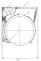
- the figures show a section of a washing machine, consisting of a washing container 1, a work surface 2, a storage container 3 for washing powder, a lid 4 for said storage container, a funnel 5, which is arranged on the bottom of said storage container and is suitable by gravity to feed detergent dispenser 6 arranged below it.
- the storage container 3 contains a plurality of movable elements 7 for crushing the lumps of detergent, the said movable elements preferably being wheels similar to the cutting wheels, each of which is cylindrical in shape and provided with a plurality of outer arms 8 and radial arms 9 which hold the said outer arms 8 and transfer the motion to it.
- the said movable elements are preferably arranged with axes running parallel to one another and are paired with one another in such a way that their axes are at a distance from one another which is smaller than the length of the radial arms 9.
- Said movable elements can rotate, and upon rotation the outer arms of each pair of elements engage in one another, engaging with one another like a pair of gearwheels which transmit the movement to one another, in such a way that all said movable elements move simultaneously and synchronously.
- the rotary movement is transmitted from a suitable drive device 10, which is arranged outside the storage container, to one of these movable elements, which also transfers the rotation to the others.
- Said drive device can exist in different functional configurations: for example it can be an electric motor which is connected to the axis of a certain movable element which also transfers the rotary movement to the other movable elements; or it can also be an electric motor which acts on suitable gears which are connected to the axes of the said movable elements, which in this case move autonomously and are not carried along by a certain element; or it can also be a simple electric rotary actuator which acts with its adjusting arm on a gear wheel which is connected to one of the movable elements; or it can also be a device that is connected to other rotary components of the washing machine, such as. B. the rotary motor of the drum, and which transmits the rotary movement, possibly via suitable deflections, to an axis of a specific movable element.
- the above-mentioned movable elements can take on a wide variety of shapes and arrangements if they are only able to perform their function effectively, which consists in stirring the lumps of detergent and thus to shred.
- You can e.g. B. have the form of rotating brushes in which the radial elements rotate in different planes so as not to interfere with each other, or they consist of real wheels 12 which are provided with a plurality of closed wings 13.
- the torque required for their movement must be greater, but this can easily be achieved with suitable reduction gears between the drive device 10 and the axes of rotation of the said vanes.
- the said movable elements are at least partially arranged in the vicinity of the inlet opening 14 of the funnel 5, as shown in FIG. 1A.
- a hinged lid 4 is provided in the working surface of the washing machine, through which the user can fill the washing powder into the storage container described.
- a network with sufficiently narrow meshes or a stiff filter element 16 with sufficiently small holes is advantageously arranged in the area of the feed opening of the aforementioned storage container, so that when the detergent is filled in, the user himself intervenes and crushes possible lumps and crushes them into powder, which is therefore can easily pass through said filter element 16.
- the washing machine is to be built over with another body, for example with a tumble dryer, as is increasingly the case, the detergent can of course no longer be filled in from above.
- Figures 5 and 5A show a drawer with a handle 51 and a flat bottom 52, on which a structure 53 is arranged, which forms sub-compartments and is open at the top and bottom, said structure under the action of the horizontal pressure caused by a suitable element 54 is exerted, slides horizontally on said plane in order to penetrate over the storage container, and is held above suitable by drawer guides 55 which prevent it from falling down.
- the method of operation is as follows: the user pulls out the drawer 52, which contains said sub-compartment construction, fills the washing powder into the sub-compartments and, by acting on said element 54, only presses the construction 53 and not the drawer inside.
- the sub-compartments, which are open on the floor, continue to reach the space above the storage container 3 and let the detergent drain into it, then the construction 54 is pulled out again and the procedure described can be repeated until the storage container is filled.
- 6 shows another way of filling the storage container: in this case, the drawer consists of several elements 61 which are shaped as sub-compartments, are telescopically connected and end at the handle 62.
- the user opens when the handle 62 is pulled out the various elements 61 up to their maximum capacity; the detergent is poured onto the container, which consists of all the above elements, and the handle is inserted. In this way, the elements are telescopically pushed into one another, their total internal volume being significantly reduced, and the amount of detergent reduced by this closing process is thereby poured into the storage container.
- FIG. 7 shows another version of a detergent filling device:
- a handle 70 is connected in an articulated manner to an open fork 71 which holds a bellows 72, the lower edges of which close the vertical detergent supply opening 74.
- the user simply lifts the handle 70 mentioned, which in turn lifts the fork 71, which extends and takes the bellows 72 with it.
- the washing powder filled into the horizontal opening 75 slips on the bellows and falls through the vertical feed opening 74 into the storage container.
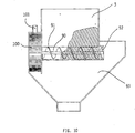
- FIGS. 11 and 11A A particularly effective and functional of these variants is shown in FIGS. 11 and 11A;
- the filling compartment 110 for washing powder has an open bottom, but which can be closed by a plurality of adjoining bulkheads 111, which can rotate about respective horizontal axes.
- the aforementioned bulkheads are articulated on a single arm 112, to which a further inner bulkhead 113 is articulated, the rear end 114 of which is provided with mutually aligned and rotatable guide means, e.g. B. two small hooks 115 and 116.
- the hooks mentioned are inserted in a fixed horizontal guide 117 which is arranged in the direction from front to back and ends in a downward curvature 118 at the rear.
- the spatial arrangement of the components is such that, when the drawer is opened, the bulkheads are rotated so that they lie essentially in the horizontal plane and thus together form a closed bottom of the drawer onto which the washing powder is filled .
- a useful improvement of the invention is to provide the user with the ability to be notified when the detergent fill is running low, ie when the reservoir needs to be refilled. This is particularly useful in view of the fact that after a certain period of use, the average user will no longer get the detergent into the machine every time they are washed to fill and therefore not knowing when this will end.
- the improvement is to provide a weight sensor located below and outside of the reservoir, as shown in FIG. 8.
- the storage container 3 is supported by one or more springs 81 which rest on a support 82 which is fastened to the housing of the machine (not shown).
- the storage container is therefore not rigidly connected to the machine, but rather is inserted into a container or vertical guides 83 which allow it to move slightly vertically, depending on the opposing forces of its weight with the detergent filling contained therein and the upward thrust caused by the aforementioned Springs 81, which are compression springs.
- An arm 88 is actuated beneath said storage container, which actuates a microswitch 85, whereby, after suitable adjustment of the various elements, the storage container rises more and more when it is emptied, until, when empty, it is raised to a point at which said arm 88 triggers microswitch 85.
- this switch operates in two different ways: it turns on an outside light and / or audible indicator that warns the user that the reservoir is empty, and it operates the machine control circuit by disabling its operation until the Storage container is filled with detergent again.
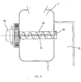
- a special type of metering device for the washing powder is therefore proposed which is significantly less susceptible to the ingress of moisture, the device mentioned being designed as described below with reference to FIG. 9: instead of feeding an opening below by falling, through which the detergent enters the washing container, the detergent storage container 3 feeds an underlying recess 90 which contains a screw 91 which can be rotated about a horizontal axis and whose outlet end 92 abuts an essentially vertical line 93. Said screw is rotated by a suitable small motor 94, the function of which can typically be controlled by the programming of the washing machine.
- the possibly penetrating moisture does not prevent the powder, even if it is slightly moistened, from still being able to be fed into the washing container, since the metering and the separation of the powder are no longer effected by gravity but by the rotational movement of the coils of said screw takes place, which "cut off" the exact amount of powder required and at the same time, by separating it from the rest of the powder, feeds it into said line 93 and from there into the washing container.
- a variant of the device just illustrated, to which FIG. 10 relates, is to replace the small motor 94 for driving the screw with a mill 100 which is driven by a water flow which flows from a suitable line 101 onto the blades the mill mentioned is directed, and wherein the rotary shaft of the mill, possibly via suitable gear, preferably reduction gear, is connected to the rotary shaft of the screw.
- the amount of detergent to be added to each cycle depends on the number of rotations of the screw and thus on the number of rotations of the mill mentioned and ultimately on the amount of water used, which can be controlled by opening the aforementioned electrovalve for a suitable period of time .
Description
Die Erfindung betrifft Wasch- und Spülmaschinen vor allem für den Haushalt mit einem verbesserten Verteiler, um das Einfüllen und Dosieren des Reinigungsmittels in Pulverform und anderer Substanzen in Pulverform, die bei diesen Wasch- und Spülmaschinen verwendet werden, zu erleichtern.The invention relates to washing machines and dishwashers, particularly for the household, with an improved distributor in order to facilitate the filling and dosing of the cleaning agent in powder form and other substances in powder form which are used in these washing machines and dishwashers.
Diese Erfindung gilt für jede beliebige Wasch- und Spülmaschine, sei es für Geschirr oder für Gewebeteile, für die Substanzen in Pulverform verwendet werden, es wird jedoch deutlich, daß die vorteilhafteste Anwendung bei Wäschewaschmaschinen stattfindet. Daher wird im Verlauf der Beschreibung auf eine Frontlade-Wäschewaschmaschine Bezug genommen, wobei unterstellt ist, daß das Beschriebene und Beanspruchte mit den offensichtlichen zweckmäßigen Änderungen auch für Wäschewaschmaschinen zum Beladen von oben und für Geschirrspüler gilt.This invention applies to any washing and dishwashing machine, be it for crockery or for fabric parts, for which substances are used in powder form, but it is clear that the most advantageous application takes place in laundry washing machines. Therefore, in the course of the description reference is made to a front loading laundry washing machine, it being assumed that the described and claimed with the obvious expedient changes also apply to laundry washing machines for loading from above and for dishwashers.
Es sind Wäschewaschmaschinen mit einem von außen herausziehbaren Schubfach bekannt, wobei das genannte Schubfach mehrere Unterfächer aufweist, in die das Waschpulver und die anderen Substanzen, die in den verschiedenen Phasen des Waschzyklus verwendet werden, eingefüllt werden. Das Schubfach wird nach seinem Befüllen wieder geschlossen und es beginnt der Waschzyklus, der zwischen den verschiedenen Vorgängen, die mittels verschiedener, nicht weiter beschriebener da allgemein bekannter Kreisläufe und Vorrichtungen erfolgen, vorsieht, daß über den genannten Unterfächern selektiv ein Wasserstrahl herabrieselt, der die genannten Substanzen in Pulverform wegschwemmt und sie durch Schwerkraft in den Waschbehälter befördert.Laundry washing machines with a drawer which can be pulled out from the outside are known, the drawer mentioned having a plurality of sub-compartments into which the washing powder and the other substances which are used in the various phases of the washing cycle are filled. The drawer is closed again after it has been filled and the washing cycle begins, which, between the various processes which take place by means of various circuits and devices which are not described in any more detail and which are known in the prior art, provides for a water jet to selectively trickle down over the sub-compartments mentioned, and these Substances in powder form are washed away and gravity-fed into the washing container.
Die genannten Vorrichtungen haben im Lauf der Jahre sehr viele Verbesserungen und Änderungen erfahren, was durch die hohe Anzahl an erteilten Patenten über diese Materie belegt wird.The devices mentioned have undergone many improvements and changes over the years, which is evidenced by the large number of patents granted on this matter.
Es hat jedoch keine dieser Verbesserungen und Patente Lösungen ausgeführt, um ein Problem zu beseitigen, das sich den Herstellern schon seit längerem stellt, wenn sie versuchen, einer sich immer deutlicher herauskristallisierenden Nachfrage des Marktes nachzukommen: Diese Nachfrage betrifft die Möglichkeit, die genannten Substanzen, jedoch hauptsächlich das Waschmittel, in solchen Mengen einfüllen zu können, daß es nicht nur für einen, sondern für mehrere Waschzyklen reicht, so daß der Maschine für eine längere Zeitdauer vollkommene Funktionsselbstständigkeit verliehen wird, wodurch der Benutzer davon befreit wird, jedes Mal die genannten Substanzen einfüllen zu müssen.However, none of these improvements and patents have implemented solutions to solve a problem that manufacturers have been facing for a long time when they try to meet an increasingly clear market demand: This demand concerns the possibility of the substances mentioned, however, it is mainly the detergent that can be added in such quantities that it lasts not just for one but for several washing cycles, so that the machine is given complete functional independence for a longer period of time, thereby releasing the user from the substances mentioned each time to fill in.
Wenn nämlich ein einmaliges Einfüllen von Waschmittel, das für zahlreiche Waschzyklen ausreicht, stattfindet, wobei die genannte Füllung direkt aus dem Waschmittelbehälter in einen dazu vorgesehenen Vorratsbehälter der Maschine geschüttet wird, von dem das Wascumittel dosiert und entnommen wird, indem es durch Schwerkraft in einen Trichter mit kontrolliertem Volumen strömt, entsteht im Inneren dieses Vorratsbehälters ein dauerhafter Druck, der sich so auswirkt, daß er das Auftreten von relativ harten und großen Waschmittelklumpen verursacht oder begünstigt.When a single detergent filling, which is sufficient for numerous washing cycles, takes place, said filling being poured directly from the detergent container into a designated storage container of the machine, from which the detergent is dosed and removed by gravity into a funnel flows with a controlled volume, a permanent pressure arises inside this storage container, which has the effect that it causes or promotes the appearance of relatively hard and large lumps of detergent.
Dieses Auftreten von Klumpenbildung beruht auf drei grundsätzlichen Ursachen: Der erste Grund besteht darin, daß diese Klumpen bereits im Originalbehälter vorhanden sind und nur in den Vorratsbehälter der Maschine übergeführt werden; der zweite Grund besteht darin, daß die relativ große Menge Waschmittel, die auch für längere Zeit gelagert sein kann, einen Druck auf die unteren Schichten des Vorrats ausübt, der auch durch die natürliche Adhäsion und Verdichtungsfähigkeit des Waschpulvers die Bildung von Klumpen bewirkt; der dritte Grund, der die beiden zuvor genannten begünstigt, ist auf die erhöhte Feuchtigkeit zurückzuführen, die von der Waschmaschine erzeugt wird und langsam in den Vorratsbehälter eindringt, wobei sie die Bildung und das Verhärten der Klumpen sehr verstärkt.This occurrence of lump formation is based on three basic causes: the first reason is that these lumps already exist in the original container and are only transferred to the machine's storage container; the second reason is that the relatively large amount of detergent, which can also be stored for a long time, exerts pressure on the lower layers of the supply, which also causes the formation of lumps by the natural adhesion and compressibility of the washing powder; the third reason, which favors the two previously mentioned, is due to the increased moisture generated by the washing machine and slowly entering the storage container, which greatly increases the formation and hardening of the lumps.
Beim nacheinander erfolgenden automatischen Dosieren des Waschmittels wird dieses in den genannten Schacht geschüttet, jedoch verstopfen vorhandene harte Klumpen schnell den genannten Schacht und behindern daher jede Art von kontrolliertem Entnehmen des Waschmittels.When the detergent is dosed automatically one after the other, it is poured into the above-mentioned shaft, but existing hard lumps quickly block the above-mentioned shaft and therefore impede any kind of controlled removal of the detergent.
Weiterhin unterliegt gegenwärtig der Füllvorgang, der vom Benutzer durchgeführt wird, Irrtümern beim Dosieren und insbesondere beim gewollten Überdosieren, das in dem unklaren Glauben geschieht, daß eine größere Menge an Waschmittel eine bessere Waschqualität zur Folge habe.Furthermore, the filling process, which is carried out by the user, is currently subject to errors in the metering and in particular in the intentional overdosing, which occurs in the unclear belief that a larger amount of detergent results in better washing quality.
Dies ist absolut nicht richtig, wie jeder Fachmann auf diesem Gebiet weiß; diese Gewohnheit, eine andere Waschmittelmenge als die optimale von den Waschmaschinenherstellern oder den Waschmittelherstellern-empfohlene einzufüllen, hat jedoch den doppelten Nachteil zur Folge, daß die erhöhte Waschmittelmenge die Kosten der einzelnen Wäsche erhöht, ohne daß sich dies in der Waschqualität zeigt, und zudem eine größere Menge an Schadstoffen nach außen entleert wird, mit den offensichtlichen negativen Auswirkungen auf die Umwelt.This is absolutely not correct, as any specialist in the field knows; However, this habit of adding a different amount of detergent than the optimal one recommended by the washing machine manufacturers or the detergent manufacturers has the double disadvantage that the increased amount of detergent increases the cost of the individual laundry without this being reflected in the washing quality, and also one larger amount of pollutants is emptied to the outside, with the obvious negative effects on the environment.
Wenn umgekehrt eine kleinere Waschmittelmenge als die optimale Dosis eingefüllt wird, ergibt dies eine Wäsche mit ungenügender Waschmittelkonzentration, die eventuell nicht zur Zufriedenheit des Benutzers ausfällt.Conversely, if a smaller amount of detergent than the optimal dose is added, this results in laundry with insufficient detergent concentration, which may not be to the satisfaction of the user.
Aus dem Stand der Technik ist die gattungsbildende US-A-25 98 227 bekannt. Diese Druckschrift offenbart ein Dosiervorrichtung für pulverförmige Stoffe, bei der in einem Vorratsbehälter die pulverförmigen Stoffe gespeichert werden. Dabei besitzt die Dosiervorrichtung ein Rührwerk, mit dem an einem Auslaß angeordnete Schneckenschraube das Pulver einer Trommel einer Waschmaschine zugeführt wird. Mit diesem Rührwerk läßt sich eine Klumpenbildung insbesondere im Randbereich des Vorratsbehälters nicht vermeiden.The generic US-A-25 98 227 is known. This document discloses a metering device for powdery substances, in which the powdery substances are stored in a storage container. The metering device has an agitator with which the powder is fed to a drum of a washing machine with the screw screw arranged at an outlet. With this agitator, lump formation, particularly in the edge area of the storage container, cannot be avoided.
Es wäre daher wünschenswert und ist Aufgabe dieser Erfindung, eine solche Vorrichtung auszuführen, daß die oben dargelegten Nachteile beseitigt werden, und die zuverlässig, ökonomisch und mit den heutigen Techniken leicht herzustellen ist.It would therefore be desirable and the object of this invention to provide such a device that the drawbacks set forth above are eliminated, and which is reliable, economical and easy to manufacture with current techniques.
Diese und weitere Aufgaben werden gelöst mit einer Art von Waschmittel-Vorratsbehälter, der in der folgenden, nur als nicht einschränkendes Beispiel und unter Bezugnahme auf die beigefügten Zeichnungen erfolgenden Beschreibung dargestellt wird, wobei
- die
Figuren 1 und 1A schematisch einen Querschnitt einer erfindungsgemäßen Waschmaschine für Wäsche bzw. ein Detail von dieser in Vergrößerung zeigen, - Fig. 1B eine Außenansicht dieser Waschmaschine zeigt,
- Fig. 2 eine perspektivische Ansicht eines Details der Vorrichtung von Fig. 1 zeigt,
- Fig. 3 eine Variante der Vorrichtung von Fig. 2 zeigt,
- Fig. 4 ein Detail der erfindungsgemäßen Vorrichtung perspektivisch von oben zeigt,
- die
Figuren - Fig. 8 eine Verbesserung der gemäß dieser Erfindung ausgeführten Vorrichtung zeigt,
- die
Figuren 9 und 10 schematisch zwei Schnittansichten von zwei erfindungsgemäßen Dosiervorrichtungen zeigen.
- FIGS. 1 and 1A schematically show a cross section of a washing machine for laundry according to the invention or a detail of this in enlarged form,
- 1B shows an external view of this washing machine,
- Figure 2 shows a perspective view of a detail of the device of Figure 1,
- 3 shows a variant of the device of FIG. 2,
- 4 shows a detail of the device according to the invention in perspective from above,
- FIGS. 5, 5A, 6, 7, 11 and 11A show some alternatives of the front filling devices for detergents,
- 8 shows an improvement of the device made according to this invention,
- FIGS. 9 and 10 schematically show two sectional views of two metering devices according to the invention.
Die Figuren zeigen einen Schnitt einer Waschmaschine, bestehend aus einem Waschbehälter 1, einer Arbeitsfläche 2, einem Vorratsbehälter 3 für Waschpulver, einem Deckel 4 für genannten Vorratsbehälter, einem Trichter 5, der am Boden des genannten Vorratsbehälters angeordnet ist und geeignet ist, mittels Schwerkraft einen unter ihm angeordneten Dosierer 6 für Waschmittel zu speisen.The figures show a section of a washing machine, consisting of a
Der Vorratsbehälter 3 enthält mehrere bewegliche Elemente 7 zum Zerkleinern der Waschmittelklumpen, wobei die genannten beweglichen Elemente vorzugsweise Räder ähnlich den Schneidrädern sind, von denen jedes zylinderartig geformt ist und mit mehreren Außenarmen 8 und radialen Armen 9 versehen ist, die die genannten Außenarme 8 halten und die Bewegung auf sie übertragen.The
Vorzugsweise sind die genannten beweglichen Elemente mit parallel zueinander verlaufenden Achsen angeordnet und miteinander dergestalt gepaart, daß ihre Achsen sich in einem Abstand voneinander befinden, der kleiner ist als die Länge der radialen Arme 9.The said movable elements are preferably arranged with axes running parallel to one another and are paired with one another in such a way that their axes are at a distance from one another which is smaller than the length of the
Daher dringen bei jedem Paar der genannten beweglichen Elemente einige Außenarme 8 eines Elements in die Form ein, die von den Außenarmen des anderen Elements umschrieben wird.Therefore, in each pair of said moving elements, some
Die genannten beweglichen Elemente können sich drehen, und bei der Drehung fassen die Außenarme jedes Elementepaars ineinander, wobei sie wie ein Paar Getrieberäder, die die Bewegung untereinander übertragen, miteinander in Eingriff kommen, dergestalt daß sich alle genannten beweglichen Elemente simultan und synchron bewegen. Die Drehbewegung wird von einer geeigneten Antriebsvorrichtung 10, die außerhalb des Vorratsbehälters angeordnet ist, auf eines dieser beweglichen Elemente übertragen, welches die Drehung auch auf die anderen überträgt.Said movable elements can rotate, and upon rotation the outer arms of each pair of elements engage in one another, engaging with one another like a pair of gearwheels which transmit the movement to one another, in such a way that all said movable elements move simultaneously and synchronously. The rotary movement is transmitted from a
Die genannte Antriebsvorrichtung kann in unterschiedlichen Funktionskonfigurationen bestehen: Zum Beispiel kann sie ein Elektromotor sein, der mit der Achse eines bestimmten beweglichen Elements verbunden ist, das die Drehbewegung auch auf die anderen beweglichen Elemente überträgt; oder sie kann auch ein Elektromotor sein, der auf geeignete Getriebe einwirkt, die mit den Achsen der genannten beweglichen Elemente verbunden sind, die sich in diesem Fall autonom bewegen und nicht von einem bestimmten Element mitgenommen werden; oder sie kann auch ein einfacher elektrischer Drehsteller sein, der mit seinem Stellarm auf ein Zahnrad einwirkt, das mit einem der beweglichen Elemente verbunden ist; oder sie kann auch eine Vorrichtung sein, die mit weiteren Drehkomponenten der Waschmaschine verbunden ist, wie z. B. der Drehmotor der Trommel, und die die Drehbewegung, eventuell über geeignete Umlenkungen, auf eine Achse eines bestimmten beweglichen Elements überträgt.Said drive device can exist in different functional configurations: for example it can be an electric motor which is connected to the axis of a certain movable element which also transfers the rotary movement to the other movable elements; or it can also be an electric motor which acts on suitable gears which are connected to the axes of the said movable elements, which in this case move autonomously and are not carried along by a certain element; or it can also be a simple electric rotary actuator which acts with its adjusting arm on a gear wheel which is connected to one of the movable elements; or it can also be a device that is connected to other rotary components of the washing machine, such as. B. the rotary motor of the drum, and which transmits the rotary movement, possibly via suitable deflections, to an axis of a specific movable element.
Natürlich können die genannten beweglichen Elemente die verschiedensten Formen und Anordnungen annehmen, wenn sie nur in der Lage sind, in wirksamer Weise ihre Funktion auszuüben, die darin besteht, die Waschmittelklumpen umzurühren und damit zu zerkleinern. Sie können z. B. die Form von drehenden Bürsten haben, bei denen die radialen Elemente in verschiedenen Ebenen drehen, um sich nicht gegenseitig zu behindern, oder sie bestehen aus wirklichen Rädern 12, die mit mehreren geschlossenen Flügeln 13 versehen sind. In diesem Fall muß selbstverständlich das erforderliche Drehmoment für ihre Bewegung größer sein, aber dies kann leicht mit geeigneten Untersetzungsgetrieben zwischen der Antriebsvorrichtung 10 und den Drehachsen der genannten Flügel erreicht werden.Of course, the above-mentioned movable elements can take on a wide variety of shapes and arrangements if they are only able to perform their function effectively, which consists in stirring the lumps of detergent and thus to shred. You can e.g. B. have the form of rotating brushes in which the radial elements rotate in different planes so as not to interfere with each other, or they consist of
Für das reibungslose Funktionieren der gesamten Vorrichtung ist es natürlich von grundsätzlicher Bedeutung, daß die genannten beweglichen Elemente wenigstens zum Teil in der Nähe der Eingangsöffnung 14 des Trichters 5 angeordnet sind, wie in Fig. 1A gezeigt.For the smooth functioning of the entire device, it is of course of fundamental importance that the said movable elements are at least partially arranged in the vicinity of the inlet opening 14 of the
Bezüglich des Einfüllens des Waschmittels in den genannten Vorratsbehälter ist vorgesehen, daß in der Arbeitsfläche der Waschmaschine ein aufklappbarer Deckel 4 ausgeführt ist, durch den der Benutzer das Waschpulver in den beschriebenen Vorratsbehälter einfüllen kann.With regard to the filling of the detergent into the storage container mentioned, it is provided that a
Vorteilhafterweise ist im Bereich der Zuführöffnung des genannten Vorratsbehälters ein Netz mit genügend engen Maschen oder ein steifes Filterelement 16 mit genügend klein bemessenen Löchern angeordnet, so daß beim Einfüllen des Waschmittels der Benutzer selbst eingreifen und mögliche Klumpen zerdrücken und sie zu Pulver zerkleinern kann, welches daher leicht durch das genannte Filterelement 16 gelangen kann.A network with sufficiently narrow meshes or a
Wenn jedoch die Waschmaschine mit einem andern Körper überbaut werden soll, beispielsweise mit einem Wäschetrockner, wie es immer häufiger der Fall ist, kann natürlich das Waschmittel nicht mehr von oben eingefüllt werden.However, if the washing machine is to be built over with another body, for example with a tumble dryer, as is increasingly the case, the detergent can of course no longer be filled in from above.
In diesem Fall ergibt sich die Notwendigkeit,von einer anderen Seite her einzufüllen, vorzugsweise im oberen Bereich der Vorderseite mittels eines Waschmittelschubfachs, das sich von den herkömmlichen Waschmittelschubfächern unterscheidet, da diese neue Art von Schubfach nicht dazu vorgesehen sein soll, eine einzige Waschmittelfüllung aufzunehmen, sondern lediglich einen Zugangsweg für das Pulver in den oben beschriebenen Vorratsbehälter bilden soll.In this case, there is a need to fill in from another side, preferably in the upper area of the front by means of a detergent drawer which differs from the conventional detergent drawers, since this new type of drawer is not intended to accommodate a single detergent filling. but should only form an access path for the powder in the storage container described above.
Zu diesem Zweck können verschiedene Ausführungsformen des genannten Schubfachs unterschieden werden, und die Figuren 5, 5A, 6, 7, 11 und 11A stellen dessen Hauptmerkmale dar.For this purpose, different embodiments of the drawer mentioned can be distinguished, and Figures 5, 5A, 6, 7, 11 and 11A represent its main features.
Die Figuren 5 und 5A zeigen ein Schubfach mit einem Handgriff 51 und einem ebenen Boden 52, auf dem eine Konstruktion 53 angeordnet wird, die Unterfächer bildet und nach oben und nach unten offen ist, wobei die genannte Konstruktion unter Einwirkung des waagrechten Drucks, der durch ein geeignetes Element 54 ausgeübt wird, auf der genannten Ebene waagrecht gleitet, um bis über den Vorratsbehälter einzudringen, und durch geeignete Schubfachführungen 55, die verhindern, daß sie herabfällt, über diesem hängend gehalten wird.Figures 5 and 5A show a drawer with a
Die Funktionsweise ist wie folgt: Der Benutzer zieht das Schubfach 52, das die genannte Unterfächer-Konstruktion enthält, heraus, füllt das Waschpulver in die Unterfächer und drückt durch Einwirkung auf das genannte Element 54 nur die Konstruktion 53 und nicht das Schubfach ins Innere. So gelangen die am Boden offenen Unterfächer immer weiter in den Raum oberhalb des Vorratsbehälters 3 und lassen das Waschmittel in ihn ab, sodann wird die Konstruktion 54 wieder herausgezogen und das beschriebene Vorgehen kann wiederholt werden, bis der Vorratsbehälter gefüllt ist. Fig. 6 zeigt eine andere Weise, den Vorratsbehälter zu füllen: In diesem Fall besteht das Schubfach aus mehreren Elementen 61, die als Unterfächer geformt sind, teleskopartig verbunden sind und am Handgriff 62 enden. Der Benutzer öffnet bei herausgezogenem Handgriff 62 die verschiedenen Elemente 61 bis zu ihrer maximalen Aufnahmefähigkeit; das Waschmittel wird auf den Behälter geschüttet, der aus allen genannten Elementen zusammen besteht, und der Handgriff wird eingeschoben. Auf diese Weise werden die Elemente teleskopartig ineinandergeschoben, wobei sich ihr Gesamtinnenvolumen deutlich verringert, und die durch diesen Verschließvorgang verringerte Waschmittelmenge wird dadurch in den Vorratsbehälter geschüttet.The method of operation is as follows: the user pulls out the
Fig. 7 zeigt eine andere Version einer Waschmitteleinfüllvorrichtung: In dieser Figur ist ein Handgriff 70 gelenkig mit einer offenen Gabel 71 verbunden, die einen Faltenbalg 72 hält, dessen untere Ränder die senkrechte Waschmittelzufuhröffnung 74 verschließen. In diesem Fall hebt der Benutzer einfach den genannten Handgriff 70 an, der seinerseits die Gabel 71 anhebt, die sich auszieht und dabei den Faltenbalg 72 mitnimmt. Das in die waagrechte Öffnung 75 eingefüllte Waschpulver rutscht auf dem Faltenbalg und fällt durch die senkrechte Zufuhröffnung 74 in den Vorratsbehälter.7 shows another version of a detergent filling device: In this figure, a
Natürlich können solche Einfüllvorrichtungen für Mehrfachfüllungen an Waschmittel in allen möglichen Konfigurationen, die im Kenntnisbereich des Fachmanns auf diesem Gebiet liegen, ausgeführt sein.Such filling devices for multiple fillings of detergent can of course be designed in all possible configurations that are within the knowledge of the person skilled in the art in this field.
Eine besonders effektive und funktionale dieser Varianten wird in den Figuren 11 und 11A gezeigt; bezugnehmend auf diese Figuren ist zu bemerken, daß das Einfüllfach 110 für Waschpulver einen offenen Boden hat, der aber durch mehrere aneinandergrenzende Schotte 111, die um jeweilige waagrechte Achsen drehen können, verschließbar ist. Die genannten Schotte sind an einem einzigen Arm 112 angelenkt, an dem auch ein weiteres inneres Schott 113 angelenkt ist, dessen hinteres Ende 114 mit miteinander ausgerichteten und drehbaren Führungsmitteln versehen ist, z. B. zwei kleinen Haken 115 und 116.A particularly effective and functional of these variants is shown in FIGS. 11 and 11A; With reference to these figures, it should be noted that the
Die genannten Haken sind in eine feststehende waagrechte Führung 117 eingesetzt, die in der Richtung von vorn nach hinten angeordnet ist und hinten in einer nach unten gerichteten Krümmung 118 endet. Die räumliche Anordnung der Komponenten ist dergestalt, daß, wenn das Schubfach geöffnet wird, die Schotte so gedreht werden, daß sie im wesentlichen in der waagrechten Ebene liegen und damit auf diese Weise zusammen einen geschlossenen Boden des Schubfachs bilden, auf den das Waschpulver gefüllt wird.The hooks mentioned are inserted in a fixed
Beim Einschieben des Schubfachs wird, wie in Fig. 11A gezeigt, das genannte innere Schott 113 wie die anderen nach innen gedrückt, und die zwei Haken 115 und 116 laufen in der Führung 117 bis zu ihrem hinteren Ende. Sobald sie die nach unten gerichtete Krümmung 118 erreichen, richten sich die genannten Haken unter Einwirkung des Drucks auf das Schubfach auf dem genannten gekrümmten Teil der Führung senkrecht aus und richten damit das zugehörige Schott 113 senkrecht aus, das bei der Drehbewegung den genannten Arm 112 vorrücken läßt, der durch die Gelenkverbindungen, mit denen er mit den verschiedenen Schotten 111 verbunden ist, deren paralleles und synchrones Drehen bewirkt, wobei sie sich in eine im wesentlichen senkrechte Ebene legen müssen.When the drawer is pushed in, as shown in FIG. 11A, the said
In dieser senkrechten Lage halten die genannten Schotte das Waschmittel nicht mehr, das daher in die darunter befindliche Leitung 119 fällt, die das Waschmittel in den Waschbehälter führt.In this vertical position, the above-mentioned bulkheads no longer hold the detergent, which therefore falls into the
Eine nützliche Verbesserung der Erfindung besteht darin, dem Benutzer die Möglichkeit zu bieten, daß ihm angezeigt wird, wenn die Waschmittelfüllung zu Ende geht, d. h. wann der Vorratsbehälter wieder aufgefüllt werden muß. Dies ist besonders nützlich in Anbetracht dessen, daß sich der Durchschnittsbenutzer nach einer gewissen Zeit der Benutzung daran gewöhnt, nicht mehr bei jeder Wäsche das Waschmittel in die Maschine zu füllen und daher nicht zu wissen, wann dieses zu Ende geht. Die Verbesserung besteht darin, einen Gewichtsfühler vorzusehen, der unter und außerhalb des Vorratsbehälters angeordnet ist, wie in Fig. 8 gezeigt.A useful improvement of the invention is to provide the user with the ability to be notified when the detergent fill is running low, ie when the reservoir needs to be refilled. This is particularly useful in view of the fact that after a certain period of use, the average user will no longer get the detergent into the machine every time they are washed to fill and therefore not knowing when this will end. The improvement is to provide a weight sensor located below and outside of the reservoir, as shown in FIG. 8.
In dieser Figur ist zu sehen, daß der Vorratsbehälter 3 von einer oder mehreren Federn 81 abgestützt wird, die auf einer Auflage 82 ruhen, die an dem Gehäuse der Maschine (nicht dargestellt) befestigt ist. Der Vorratsbehälter ist also nicht starr mit der Maschine verbunden, sondern in einen Behälter oder senkrechte Führungen 83 eingesetzt, die ihm eine leichte senkrechte Bewegung erlauben, je nach den gegeneinanderwirkenden Kräften seines Gewichts mit der in ihm enthaltenen Waschmittelfüllung und des Schubs nach oben durch die genannten Federn 81, die Druckfedern sind.In this figure it can be seen that the
Unter den genannten Vorratsbehälter wird ein Arm 88 angelegt, der einen Mikroschalter 85 betätigt, wodurch nach geeigneter Einstellung der verschiedenen Elemente der Vorratsbehälter sich bei seinem Entleeren immer mehr hebt, bis er, wenn er leer ist, bis zu einem Punkt angehoben ist, bei dem der genannte Arm 88 den Mikroschalter 85 auslöst.An
Vorteilhafterweise wird dieser Schalter auf zwei verschiedene Weisen tätig: er schaltet außen eine Leucht- und/oder akkustische Anzeige ein, die den Benutzer warnt, daß der Vorratsbehälter leer ist, und er betätigt den Steuerkreis der Maschine, indem ihr Betrieb gesperrt wird, bis der Vorratsbehälter erneut mit Waschmittel gefüllt ist.Advantageously, this switch operates in two different ways: it turns on an outside light and / or audible indicator that warns the user that the reservoir is empty, and it operates the machine control circuit by disabling its operation until the Storage container is filled with detergent again.
Die oben dargestellten Vorrichtungen können vorteilhaft mit Dosiervorrichtungen wie z. B. der in dem genannten Patent beschriebenen Vorrichtung verbunden werden; diese Art von Vorrichtung weist jedoch den Nachteil auf, daß bei einem Eindringen von Feuchtigkeit in den Waschmittelvorratsbehälter das Waschpulver, das die genannte Feuchtigkeit aufnimmt, dazu neigt, zu klumpen und den Durchgang nach unten für das Herabfallen dieses Waschmittels zu verstopfen.The devices shown above can advantageously with dosing devices such. B. the device described in said patent; however, this type of device has the disadvantage that in the event of moisture penetrating into the detergent storage container the washing powder, which absorbs the said moisture, tends to clump and clog the passage downwards for this detergent to fall down.
Es wird daher eine besondere Art von Dosiervorrichtung für das Waschpulver vorgeschlagen, die gegen das Eindringen von Feuchtigkeit bedeutend weniger anfällig ist, wobei die genannte Vorrichtung gemäß der folgenden Beschreibung unter Bezugnahme auf Fig. 9 ausgeführt ist: Anstatt durch Herabfallen eine untenliegende Öffnung zu speisen, durch die das Waschmittel in den Waschbehälter gelangt, speist der Waschmittelvorratsbehälter 3 eine untenliegende Aussparung 90, die eine um eine waagrechte Achse drehbare Schnecke 91 enthält, deren Ausgangsende 92 in eine im wesentlichen senkrechte Leitung 93 stößt. Die genannte Schnecke wird von einem geeigneten kleinen Motor 94, dessen Funktion in typischer Weise von der Programmierung der Waschmaschine gesteuert werden kann, in Drehbewegung versetzt.A special type of metering device for the washing powder is therefore proposed which is significantly less susceptible to the ingress of moisture, the device mentioned being designed as described below with reference to FIG. 9: instead of feeding an opening below by falling, through which the detergent enters the washing container, the
Mit dieser Vorrichtung verhindert die möglicherweise eindringende Feuchtigkeit nicht, daß das Pulver, selbst wenn es ein wenig angefeuchtet ist, dennoch in den Waschbehälter zugeführt werden kann, da das Dosieren und die Abtrennung des Pulvers nicht mehr durch Schwerkraft, sondern bewirkt durch die Drehbewegung der Wendeln der genannten Schnecke erfolgt, die die genaue erforderliche Pulvermenge "abschneiden" und zugleich, indem sie sie vom Rest des Pulvers trennen, in die genannte Leitung 93 und von dort in den Waschbehälter befördern.With this device, the possibly penetrating moisture does not prevent the powder, even if it is slightly moistened, from still being able to be fed into the washing container, since the metering and the separation of the powder are no longer effected by gravity but by the rotational movement of the coils of said screw takes place, which "cut off" the exact amount of powder required and at the same time, by separating it from the rest of the powder, feeds it into said
Eine Variante der soeben dargestellten Vorrichtung, auf die sich Fig. 10 bezieht, besteht darin, den kleinen Motor 94 für den Antrieb der Schnecke durch eine Mühle 100 zu ersetzen, die durch einen Wasserstrom angetrieben wird, der aus einer geeigneten Leitung 101 auf die Schaufeln der genannten Mühle gerichtet ist, und wobei die Drehwelle der Mühle, eventuell über geeignete Getriebe, vorzugsweise Reduziergetriebe, mit der Drehwelle der Schnecke verbunden ist.A variant of the device just illustrated, to which FIG. 10 relates, is to replace the
Auf diese Weise vermeidet man, den Motor 94 verwenden zu müssen, dessen Funktion von der genannten Mühle und dem Wasserstrom ausgeführt wird, der, da er einen ausreichenden Druck besitzen muß, leicht aus einer Ableitung der Hauptwasserzufuhrleitung der Maschine entnommen und von einem geeigneten, nicht dargestellten Elektroventil gesperrt werden kann.In this way one avoids having to use the
Auf diese Weise hängt die bei jedem Zyklus zuzuführende Waschmittelmenge von der Anzahl der Drehungen der Schnecke und damit von der Anzahl der Drehungen der genannten Mühle und letztendlich von der verwendeten Wassermenge ab, die geregelt werden kann, indem das genannte Elekrtoventil für eine geeignete Zeitspanne geöffnet wird.In this way, the amount of detergent to be added to each cycle depends on the number of rotations of the screw and thus on the number of rotations of the mill mentioned and ultimately on the amount of water used, which can be controlled by opening the aforementioned electrovalve for a suitable period of time .
Für den Fachmann auf diesem Gebiet ist es offensichtlich, daß leicht weitere Lösungen gefunden werden können, bei denen verschiedene Weisen der Verteilung und Steuerung des Wasserstroms zur Betätigung der genannten Mühle verwendet werden, je nachdem ob dieser Strom vor oder nach der Sicherheitsvorrichtung entnommen wird.It will be apparent to those skilled in the art that other solutions can easily be found using various ways of distributing and controlling the flow of water to operate the mill, depending on whether that flow is taken before or after the safety device.
Es versteht sich, daß das Beschriebene und unter Bezugnahme auf die beigefügten Zeichnungen Dargestellte lediglich als Beispiel für die Erfindung dargelegt wurde und daß zahlreiche Varianten und Änderungen ausgeführt werden können, ohne den geschützten Rahmen des Patents zu verlassen.It is understood that what has been described and illustrated with reference to the accompanying drawings has been presented only as an example of the invention and that numerous variants and changes can be made without departing from the protected scope of the patent.
Claims (15)
- Washing machine and dishwasher, in particular for domestic use, consisting of a washing container (1), a storage container (3) for washing powder, a dosing device (6) for this washing agent, in input aperture (14) in this dosing device, a duct, which connects this dosing device to said washing container, wherein the storage container (3) contains a plurality of doses of washing agent, which can deliver the necessary washing agent to the machine if a plurality of washing cycles are to be performed one after the other, and the washing agent is periodically mixed in said storage container by a plurality of moveable elements (7), characterised in that said moveable elements are disposed with their axes parallel to one another and engage in one another in such a manner that the shafts thereof are located at a distance from one another, which distance is less than the length of the radial arms (9), said moveable elements can rotate and in that, during the rotation, the outer arms (9) of each element pair engage in one another, wherein they transfer the movement to one another.
- Washing machine according to Claim 1, characterised in that said moveable elements are formed by wheels (12), which are provided with a plurality of closed blades (13).
- Washing machine according to Claim 1 or 2, characterised in that said moveable elements (7) are actuated by an appropriate drive device (10).
- Washing machine according to Claim 3, characterised in that said drive device (10) is a motor which is connected to the shaft of a given moveable element, or in that it is a motor which acts on appropriate gears, which gears are connected to the shafts of said moveable elements, or that it is an electrical rotary actuator, which acts on a toothed wheel with its setting arm, which wheel is connected to the shaft of one of the moveable elements.
- Washing machine according to Claim 3 or Claim 4, characterised in that a reducing gear is disposed between said drive device (10) and said moveable elements (7).
- Washing machine according to one of the preceding Claims, characterised in that a lid (4) which is capable of being swung open is provided in the working surface, through which lid said storage container (3) is accessible.
- Washing machine according to Claim 6, characterised in that, in the vicinity of the supply aperture of said storage container, there is provided a grid or a filter element (16) with holes.
- Washing machine according to one of Claim 1 to 7, characterised in that it is provided with a drawer, which is held in a suspended manner over said storage container (3) by means of appropriate drawer guides (55), and is provided with a handle (51) and with a flat base (52) on which there is disposed a construction (53) which slides horizontally on said plane, forms subcompartments, is open towards the bottom and towards the top and is provided with an element (54) which is appropriate for pushing said construction.
- Washing machine according to one of Claims 1 to 7, characterised in that it is provided with a drawer, which consists of a plurality of elements (61), which are formed as subcompartments, are connected in a telescopelike manner and end in a handle (62).
- Washing machine according to any one of claims 1 to 7, characterised in that it is provided with a handle (70), which is connected in an articulated manner to an open cradle (71), which cradle delimits the horizontal supply aperture (75) for washing agents and retains a concertina wall (72), which can be closed around the perpendicular washing agent supply aperture (74).
- Washing machine according to any one of Claims 1 to 7, characterised in that it is provided with a drawer (110) for introducing washing agent, which drawer has an open base but which can, however, be closed by means of a plurality of adjacent partitions (111) which can rotate about horizontal shafts in each case and which are connected in an articulated manner to a single arm (112), to which an inner partition (113) is also connected in an articulated manner, the rear end (114) of which is provided with guide means (115, 116) which are aligned with one another and are rotatable, wherein said means are installed in a horizontal guide (117) which is disposed in the direction from the front to the rear and ends at the rear in a curvature (118).
- Washing machine according to one of the preceding Claims, characterised in that the storage container (3) is supported by a plurality of springs (81) which bear on a support (82) which is secured on the casing of the machine, wherein said storage container is mounted in a container with perpendicular guides (83), the base of which forms a control surface of the position of said storage container, on which an arm (88) is mounted in an articulated manner, which arm actuates an appropriate switch (85) which can display the alterations of the position of said storage container at the exterior.
- Washing machine according to one of the preceding Claims, characterised in that the washing agent container (3) supplies a recess (90) located at the bottom, which recess contains a screw (91) which may be rotated about a horizontal axis and the outlet end (92) of which enters into a substantially perpendicular duct (93), wherein said screw is displaced in the direction of rotation by means of an appropriate motor (94), the function of which can be controlled by the programming of the washing machine.
- Washing machine according to Claim 13, characterised in that the motor (94) for driving the screw is replaced by a mill (100), which is supplied with a flow of water, which originates from an appropriate duct (101), wherein said rotational shaft of the mill is connected to the rotational shaft of the screw, optionally via appropriate transmission means.
- Washing machine according to Claim 14, characterised in that said duct (101) comes from a branch of the main water supply duct of the machine through an appropriate controllable locking valve for this duct.
Applications Claiming Priority (2)
| Application Number | Priority Date | Filing Date | Title |
|---|---|---|---|
| ITPN920088A IT1259236B (en) | 1992-11-27 | 1992-11-27 | WASHING MACHINES WITH PERFECTED DETERGENT DISPENSER. |
| ITPN920088 | 1992-11-27 |
Publications (2)
| Publication Number | Publication Date |
|---|---|
| EP0599110A1 EP0599110A1 (en) | 1994-06-01 |
| EP0599110B1 true EP0599110B1 (en) | 1997-02-12 |
Family
ID=11394727
Family Applications (1)
| Application Number | Title | Priority Date | Filing Date |
|---|---|---|---|
| EP93117902A Expired - Lifetime EP0599110B1 (en) | 1992-11-27 | 1993-11-04 | Washing machines and dish washers with an improved detergent dispenser |
Country Status (4)
| Country | Link |
|---|---|
| EP (1) | EP0599110B1 (en) |
| DE (1) | DE59305448D1 (en) |
| ES (1) | ES2097422T3 (en) |
| IT (1) | IT1259236B (en) |
Cited By (2)
| Publication number | Priority date | Publication date | Assignee | Title |
|---|---|---|---|---|
| US7754025B1 (en) | 2000-06-08 | 2010-07-13 | Beverage Works, Inc. | Dishwasher having a door supply housing which holds dish washing supply for multiple wash cycles |
| US8190290B2 (en) | 2000-06-08 | 2012-05-29 | Beverage Works, Inc. | Appliance with dispenser |
Families Citing this family (9)
| Publication number | Priority date | Publication date | Assignee | Title |
|---|---|---|---|---|
| DE19740819A1 (en) * | 1997-09-17 | 1999-03-18 | Ako Werke Gmbh & Co | Apparatus for dispensing detergent powder into dishwashers etc. |
| WO2003027377A1 (en) * | 2001-09-12 | 2003-04-03 | Cading Konstruktions Gmbh Für Maschinenbau | Reservoir dosing device for pre-charging and dosing of liquid detergents in household devices |
| WO2003044256A1 (en) * | 2001-11-08 | 2003-05-30 | Arçelik A. S. | A household appliance |
| KR100446493B1 (en) * | 2002-07-26 | 2004-09-01 | 삼성전자주식회사 | Washing Machine |
| DE102004045446A1 (en) * | 2004-09-18 | 2006-03-23 | Premark Feg L.L.C., Wilmington | Dishwasher with at least one supply device for providing a Spülzusatzes |
| IT1390915B1 (en) * | 2008-07-24 | 2011-10-19 | Indesit Co Spa | WASHING MACHINE INCLUDING A DRAWER FOR WASHING AGENTS |
| CN113818214A (en) * | 2020-06-19 | 2021-12-21 | 青岛海尔洗衣机有限公司 | Detergent dissolving device and washing machine |
| CN113818212A (en) * | 2020-06-19 | 2021-12-21 | 青岛海尔洗衣机有限公司 | Detergent box assembly and washing machine |
| CN113818213B (en) * | 2020-06-19 | 2024-03-01 | 青岛海尔洗衣机有限公司 | Detergent box and washing machine |
Family Cites Families (5)
| Publication number | Priority date | Publication date | Assignee | Title |
|---|---|---|---|---|
| US2514000A (en) * | 1945-08-20 | 1950-07-04 | Sophia Tank | Dishwashing apparatus |
| US2598227A (en) * | 1948-03-12 | 1952-05-27 | Avco Mfg Corp | Injector for powdered materials |
| DE2501969B2 (en) * | 1975-01-18 | 1981-04-16 | Licentia Patent-Verwaltungs-Gmbh, 6000 Frankfurt | Arrangement for controlling washing machines and dishwashers |
| CN1003659B (en) * | 1986-02-06 | 1989-03-22 | 株式会社东芝 | Device for adding washing agent in washing machines |
| DE3721381A1 (en) * | 1987-06-29 | 1989-01-19 | Henkel Kgaa | POWDER DOSING DEVICE |
-
1992
- 1992-11-27 IT ITPN920088A patent/IT1259236B/en active IP Right Grant
-
1993
- 1993-11-04 ES ES93117902T patent/ES2097422T3/en not_active Expired - Lifetime
- 1993-11-04 EP EP93117902A patent/EP0599110B1/en not_active Expired - Lifetime
- 1993-11-04 DE DE59305448T patent/DE59305448D1/en not_active Expired - Fee Related
Cited By (12)
| Publication number | Priority date | Publication date | Assignee | Title |
|---|---|---|---|---|
| US7754025B1 (en) | 2000-06-08 | 2010-07-13 | Beverage Works, Inc. | Dishwasher having a door supply housing which holds dish washing supply for multiple wash cycles |
| US8103378B2 (en) | 2000-06-08 | 2012-01-24 | Beverage Works, Inc. | Appliance having a user interface panel and a beverage dispenser |
| US8190290B2 (en) | 2000-06-08 | 2012-05-29 | Beverage Works, Inc. | Appliance with dispenser |
| US8290616B2 (en) | 2000-06-08 | 2012-10-16 | Beverage Works, Inc. | Appliance having a user interface panel and a beverage dispenser |
| US8290615B2 (en) | 2000-06-08 | 2012-10-16 | Beverage Works, Inc. | Appliance with dispenser |
| US8548624B2 (en) | 2000-06-08 | 2013-10-01 | Beverage Works, Inc. | Appliance having a user interface panel and a beverage dispenser |
| US8565917B2 (en) | 2000-06-08 | 2013-10-22 | Beverage Works, Inc. | Appliance with dispenser |
| US8606395B2 (en) | 2000-06-08 | 2013-12-10 | Beverage Works, Inc. | Appliance having a user interface panel and a beverage dispenser |
| US9090447B2 (en) | 2000-06-08 | 2015-07-28 | Beverage Works, Inc. | Appliance having a user interface panel and a beverage dispenser |
| US9090449B2 (en) | 2000-06-08 | 2015-07-28 | Beverage Works, Inc. | Appliance having a user interface panel and a beverage dispenser |
| US9090448B2 (en) | 2000-06-08 | 2015-07-28 | Beverage Works, Inc. | Appliance having a user interface panel and a beverage dispenser |
| US9090446B2 (en) | 2000-06-08 | 2015-07-28 | Beverage Works, Inc. | Appliance with dispenser |
Also Published As
| Publication number | Publication date |
|---|---|
| DE59305448D1 (en) | 1997-03-27 |
| EP0599110A1 (en) | 1994-06-01 |
| IT1259236B (en) | 1996-03-11 |
| ITPN920088A1 (en) | 1994-05-27 |
| ES2097422T3 (en) | 1997-04-01 |
| ITPN920088A0 (en) | 1992-11-27 |
Similar Documents
| Publication | Publication Date | Title |
|---|---|---|
| EP0906747A2 (en) | Device for a dosed dispensing of powder cleaning product in a cleaning machine using water | |
| DE69413064T2 (en) | AUTOMATIC DOSING DEVICE FOR GRINDING | |
| EP0599110B1 (en) | Washing machines and dish washers with an improved detergent dispenser | |
| DE10059183A1 (en) | beverage machine | |
| DE102007037883A1 (en) | Multiple addition valve for a system for dosing liquid or pasty detergents and method for operating the multiple-addition valve | |
| EP2185843B1 (en) | Multiple-addition valve for a system for metering liquid or paste-like auxiliary washing agents | |
| EP3468440B1 (en) | Metering device for shaped cleaning-agent bodies in domestic dishwashers | |
| DE102018130256A1 (en) | Washing machine for laundry and method of operating it | |
| DE2108031A1 (en) | Ice dispenser for ice cubes and crushed ice | |
| EP2446079B1 (en) | Washing machine with automatic controlled dispensing device | |
| DE1812654B2 (en) | DEVICE FOR AUTOMATIC PREPARATION OF COFFEE | |
| EP3629880A1 (en) | Domestic dishwasher having a metering device | |
| DE2006930A1 (en) | Machine for the preparation of infusion beverages, in particular espresso coffee | |
| DE60202387T2 (en) | Dispenser for dishwasher or washing machine | |
| DE19545773A1 (en) | Device for in-feed of cleaning agent and rinsing agent into dish- washing machine | |
| DE3730405A1 (en) | Washing-agent flushing-in device, especially for washing machines | |
| DE19848370A1 (en) | Ground coffee preparation machine with powder measuring unit, compression and infusion unit and used grounds ejection unit | |
| WO2020043799A1 (en) | Dishwasher, method for operating a dishwasher, and computer program product | |
| EP3468439A1 (en) | Metering device for shaped cleaning-agent bodies in domestic dishwashers | |
| DE19535153B4 (en) | Device for feeding washing-up liquid for dishwashers | |
| DE102017207649B4 (en) | Dishwasher and method for operating a dishwasher | |
| DE102017208013A1 (en) | Dosing device for detergent tablets for a dishwasher, dishwasher and method for operating a dishwasher | |
| DE19841110B4 (en) | Detergent dispenser for a dishwasher | |
| DE19511789A1 (en) | Volumetric dispensing discharge device for detergent | |
| DE6927044U (en) | PROGRAM CONTROLLED DETERGENT DISPENSING DEVICE FOR WASHING MACHINES. |
Legal Events
| Date | Code | Title | Description |
|---|---|---|---|
| PUAI | Public reference made under article 153(3) epc to a published international application that has entered the european phase |
Free format text: ORIGINAL CODE: 0009012 |
|
| AK | Designated contracting states |
Kind code of ref document: A1 Designated state(s): DE ES FR GB IT |
|
| 17P | Request for examination filed |
Effective date: 19940511 |
|
| 17Q | First examination report despatched |
Effective date: 19951222 |
|
| GRAG | Despatch of communication of intention to grant |
Free format text: ORIGINAL CODE: EPIDOS AGRA |
|
| RAP1 | Party data changed (applicant data changed or rights of an application transferred) |
Owner name: ELECTROLUX ZANUSSI ELETTRODOMESTICI S.P.A. |
|
| GRAH | Despatch of communication of intention to grant a patent |
Free format text: ORIGINAL CODE: EPIDOS IGRA |
|
| GRAH | Despatch of communication of intention to grant a patent |
Free format text: ORIGINAL CODE: EPIDOS IGRA |
|
| ITF | It: translation for a ep patent filed |
Owner name: PROPRIA PROTEZIONE PROPR. IND. |
|
| GRAA | (expected) grant |
Free format text: ORIGINAL CODE: 0009210 |
|
| AK | Designated contracting states |
Kind code of ref document: B1 Designated state(s): DE ES FR GB IT |
|
| GBT | Gb: translation of ep patent filed (gb section 77(6)(a)/1977) |
Effective date: 19970214 |
|
| ET | Fr: translation filed | ||
| REF | Corresponds to: |
Ref document number: 59305448 Country of ref document: DE Date of ref document: 19970327 |
|
| REG | Reference to a national code |
Ref country code: ES Ref legal event code: FG2A Ref document number: 2097422 Country of ref document: ES Kind code of ref document: T3 |
|
| PLBE | No opposition filed within time limit |
Free format text: ORIGINAL CODE: 0009261 |
|
| STAA | Information on the status of an ep patent application or granted ep patent |
Free format text: STATUS: NO OPPOSITION FILED WITHIN TIME LIMIT |
|
| 26N | No opposition filed | ||
| REG | Reference to a national code |
Ref country code: FR Ref legal event code: TP |
|
| REG | Reference to a national code |
Ref country code: GB Ref legal event code: 732E |
|
| REG | Reference to a national code |
Ref country code: ES Ref legal event code: PC2A |
|
| REG | Reference to a national code |
Ref country code: GB Ref legal event code: IF02 |
|
| PGFP | Annual fee paid to national office [announced via postgrant information from national office to epo] |
Ref country code: DE Payment date: 20081119 Year of fee payment: 16 |
|
| PGFP | Annual fee paid to national office [announced via postgrant information from national office to epo] |
Ref country code: ES Payment date: 20081111 Year of fee payment: 16 |
|
| PGFP | Annual fee paid to national office [announced via postgrant information from national office to epo] |
Ref country code: IT Payment date: 20081106 Year of fee payment: 16 |
|
| PGFP | Annual fee paid to national office [announced via postgrant information from national office to epo] |
Ref country code: FR Payment date: 20081013 Year of fee payment: 16 |
|
| PGFP | Annual fee paid to national office [announced via postgrant information from national office to epo] |
Ref country code: GB Payment date: 20081022 Year of fee payment: 16 |
|
| GBPC | Gb: european patent ceased through non-payment of renewal fee |
Effective date: 20091104 |
|
| REG | Reference to a national code |
Ref country code: FR Ref legal event code: ST Effective date: 20100730 |
|
| PG25 | Lapsed in a contracting state [announced via postgrant information from national office to epo] |
Ref country code: FR Free format text: LAPSE BECAUSE OF NON-PAYMENT OF DUE FEES Effective date: 20091130 |
|
| PG25 | Lapsed in a contracting state [announced via postgrant information from national office to epo] |
Ref country code: DE Free format text: LAPSE BECAUSE OF NON-PAYMENT OF DUE FEES Effective date: 20100601 |
|
| PG25 | Lapsed in a contracting state [announced via postgrant information from national office to epo] |
Ref country code: GB Free format text: LAPSE BECAUSE OF NON-PAYMENT OF DUE FEES Effective date: 20091104 |
|
| REG | Reference to a national code |
Ref country code: ES Ref legal event code: FD2A Effective date: 20110309 |
|
| PG25 | Lapsed in a contracting state [announced via postgrant information from national office to epo] |
Ref country code: IT Free format text: LAPSE BECAUSE OF NON-PAYMENT OF DUE FEES Effective date: 20091104 |
|
| PG25 | Lapsed in a contracting state [announced via postgrant information from national office to epo] |
Ref country code: ES Free format text: LAPSE BECAUSE OF NON-PAYMENT OF DUE FEES Effective date: 20110308 |
|
| PG25 | Lapsed in a contracting state [announced via postgrant information from national office to epo] |
Ref country code: ES Free format text: LAPSE BECAUSE OF NON-PAYMENT OF DUE FEES Effective date: 20091105 |