EP0597610B1 - Flüssigkeitsdruck-Quelle für Flüssigkeitsbetätigten Verstärker - Google Patents
Flüssigkeitsdruck-Quelle für Flüssigkeitsbetätigten Verstärker Download PDFInfo
- Publication number
- EP0597610B1 EP0597610B1 EP93308644A EP93308644A EP0597610B1 EP 0597610 B1 EP0597610 B1 EP 0597610B1 EP 93308644 A EP93308644 A EP 93308644A EP 93308644 A EP93308644 A EP 93308644A EP 0597610 B1 EP0597610 B1 EP 0597610B1
- Authority
- EP
- European Patent Office
- Prior art keywords
- liquid
- accumulator
- throttle valve
- valve unit
- pressure
- Prior art date
- Legal status (The legal status is an assumption and is not a legal conclusion. Google has not performed a legal analysis and makes no representation as to the accuracy of the status listed.)
- Expired - Lifetime
Links
Images


Classifications
-
- F—MECHANICAL ENGINEERING; LIGHTING; HEATING; WEAPONS; BLASTING
- F04—POSITIVE - DISPLACEMENT MACHINES FOR LIQUIDS; PUMPS FOR LIQUIDS OR ELASTIC FLUIDS
- F04B—POSITIVE-DISPLACEMENT MACHINES FOR LIQUIDS; PUMPS
- F04B11/00—Equalisation of pulses, e.g. by use of air vessels; Counteracting cavitation
- F04B11/0091—Equalisation of pulses, e.g. by use of air vessels; Counteracting cavitation using a special shape of fluid pass, e.g. throttles, ducts
-
- B—PERFORMING OPERATIONS; TRANSPORTING
- B60—VEHICLES IN GENERAL
- B60T—VEHICLE BRAKE CONTROL SYSTEMS OR PARTS THEREOF; BRAKE CONTROL SYSTEMS OR PARTS THEREOF, IN GENERAL; ARRANGEMENT OF BRAKING ELEMENTS ON VEHICLES IN GENERAL; PORTABLE DEVICES FOR PREVENTING UNWANTED MOVEMENT OF VEHICLES; VEHICLE MODIFICATIONS TO FACILITATE COOLING OF BRAKES
- B60T8/00—Arrangements for adjusting wheel-braking force to meet varying vehicular or ground-surface conditions, e.g. limiting or varying distribution of braking force
- B60T8/32—Arrangements for adjusting wheel-braking force to meet varying vehicular or ground-surface conditions, e.g. limiting or varying distribution of braking force responsive to a speed condition, e.g. acceleration or deceleration
- B60T8/34—Arrangements for adjusting wheel-braking force to meet varying vehicular or ground-surface conditions, e.g. limiting or varying distribution of braking force responsive to a speed condition, e.g. acceleration or deceleration having a fluid pressure regulator responsive to a speed condition
- B60T8/40—Arrangements for adjusting wheel-braking force to meet varying vehicular or ground-surface conditions, e.g. limiting or varying distribution of braking force responsive to a speed condition, e.g. acceleration or deceleration having a fluid pressure regulator responsive to a speed condition comprising an additional fluid circuit including fluid pressurising means for modifying the pressure of the braking fluid, e.g. including wheel driven pumps for detecting a speed condition, or pumps which are controlled by means independent of the braking system
- B60T8/4068—Arrangements for adjusting wheel-braking force to meet varying vehicular or ground-surface conditions, e.g. limiting or varying distribution of braking force responsive to a speed condition, e.g. acceleration or deceleration having a fluid pressure regulator responsive to a speed condition comprising an additional fluid circuit including fluid pressurising means for modifying the pressure of the braking fluid, e.g. including wheel driven pumps for detecting a speed condition, or pumps which are controlled by means independent of the braking system the additional fluid circuit comprising means for attenuating pressure pulsations
-
- F—MECHANICAL ENGINEERING; LIGHTING; HEATING; WEAPONS; BLASTING
- F04—POSITIVE - DISPLACEMENT MACHINES FOR LIQUIDS; PUMPS FOR LIQUIDS OR ELASTIC FLUIDS
- F04B—POSITIVE-DISPLACEMENT MACHINES FOR LIQUIDS; PUMPS
- F04B11/00—Equalisation of pulses, e.g. by use of air vessels; Counteracting cavitation
- F04B11/0008—Equalisation of pulses, e.g. by use of air vessels; Counteracting cavitation using accumulators
- F04B11/0016—Equalisation of pulses, e.g. by use of air vessels; Counteracting cavitation using accumulators with a fluid spring
Definitions
- This invention relates to a liquid pressure source unit which is to be mounted on a brake system of a vehicle, etc., and particularly to a liquid pressure source unit of the type which includes a throttle valve unit for damping pulsation pressure and operated to supply power pressure to a liquid-operated booster.
- a liquid pressure source unit of this type comprises a hydraulic pressure pump actuated by an external power source.
- the pump is arranged to draw and discharge hydraulic liquid, an accumulator being connected to accumulate pressurized liquid discharged from the pump in a predetermined range of pressure and supply such accumulated pressurized liquid to a liquid-operated brake circuit.
- pressurized liquid discharged from the hydraulic pressure pump is liable to generate pulsation, which gives rise to the problem of vibrations and noise.
- This problem is more significant in a reciprocal type pump for reciprocating a plunger using an eccentric cam than in a radial piston type pump in which a piston disposed within a rotor is reciprocally moved in a radial direction of the rotor by rotating the rotor relative to an eccentric stator.
- the pulsation pressure also affects adversely the accumulator and even the liquid-operated booster which utilises the pressurized liquid of the accumulator, by reducing their tolerance.
- the pulsation is even further transmitted to a brake pedal in the brake circuit to adversely affect the driver's feel of operation with respect to the pedal.
- Japanese Laid-Open Utility Model Application No Hei 3-129785 discloses a technique for reducing vibrations and noise due to pulsation pressure by providing a pulsation damping device which includes a pressure receiving member which under the influence of the pressure discharged by a reciprocal type pump is moved toward an outlet port of the pump against the force of a spring.
- the technique for providing an elastic pressure receiving member at an outlet port of a pump is also known from US Patent No 5, 096, 400.
- Another US Patent No 4, 988, 147 discloses a technique for providing an accumulation chamber and a fixed throttle having a constant throttling function at an outlet port of a pump.
- the diameter of the fixed throttle is, for example, 1mm or less. Taking the load of the pump into consideration, the diameter of the fixed throttle is 0.1mm order (normally 0.5mm, for example).
- the liquid-operated booster itself is well known from, for example, US Patent No 5, 168. 791 and some others. Those techniques for reducing such pulsation pressure are good enough for reducing vibrations and noises of the system including the hydraulic pressure pump, the accumulator, and the liquid-operated booster, and are also effective in enhancing the tolerance of the devices.
- EP-A-407 721 (corresponds US 5 058 961) discloses a throttle 34 for reducing a pulsation pressure produced by a pump 29.
- a pressure limiting valve 33 is connected in parallel with the throttle 34, the whole assembly being connected on the remote side of a damper chamber 32 from the pump 29.
- the damper chamber 32, the pressure limiting valve 33 and the throttle 34 form an apparatus for damping pressure fluctuations engendered by the operation of the pump 29.
- GB 2 193 770A discloses a liquid pressure source unit for a liquid operated booster 17 which features a tube 24 provided at an entrance part of an accumulator 13.
- the additional noise differs from that associated with large vibrations and seems to draw the driver's attention. That is, the additional noise is a big problem for the driver, etc. and needs to be solved separately from the noises and vibrations due to the pressurised liquid.
- the additional noise occurs not only in the reciprocal type pump but also in the radial piston type pump which generates less vibrations and noises.
- a liquid pressure system comprising a liquid-operated booster (90) comprising a hydraulic pressure pump (10) adapted to draw hydraulic liquid and discharge pressurized liquid, and an accumulator (70) for accumulating the pressurized liquid discharged from said hydraulic pressure pump (10), the pressurised liquid accumulated in said accumulator (70) being supplied to said liquid-operated booster (90), characterised in that a throttle valve unit (80, 800, 180, 280) is provided between the accumulator (70) and the liquid-operated booster (90) and adapted to greatly reduce a flow area until a pressure differential or a flow rate reaches a predetermined value, the throttle valve unit (80, 800, 180, 280) having a throttling function equivalent to a hole of 0.01 mm order in diameter which serves to reduce noise in the booster, the throttle valve unit (80, 800, 180, 280) having a member (82, 185, 285) movable between a first position in which the throttle (S) has
- This throttle valve unit functions as such that when the liquid-operated booster is abruptly actuated, the flow of the pressurized liquid from the accumulator toward the liquid-operated booster is slightly delayed, so that the flow rate at the valve portion of the booster will be restrained. As a result, noise, which would otherwise be generated by a large flow rate, is not generated.
- Fig. 1 is a sectional view of an overall construction of a pressure source unit of the present invention, showing various component parts of a radial piston type pump adjacent to a motor, and an accumulator integral with the pump.
- An important portion of the pump 10 is present within a recess 14 of a housing 11.
- An electric drive motor 12 acting as a power source is situated at a side portion of the housing 11 with a closure member 20 disposed therebetween.
- the closure member 20 has such a function as to close an open end of the recess 14.
- the member 20 has such a function as to retain an oil seal ring 13 which is mounted around a drive shaft 121 in order to seal the peripheral area of the drive shaft.
- the housing 11 is made of aluminum or aluminum-contained alloy.
- the recess 14 of the housing 11 is a stepped-bore having five steps.
- a first bore 14a on the open end side has a largest diameter, and a second bore 14b, a third bore 14c, a fourth bore 14d and a fifth bore 14e are steppingly reduced in diameter in this order.
- a central shaft 30 is fixedly supported within the fifth bore 14e of the recess 14. One end of the central shaft 30 is disposed within the fifth bore 14e, while the other end thereof extends so far as to the first bore 14a side.
- a rotor 40 is supported by that portion of the central shaft 30 projecting from the fifth bore 14e.
- the rotor 40 is connected to the drive shaft 121 of the electric drive motor 12 through an elastic coupling 42.
- the rotor 20 rotates about the central shaft 30 in accordance with the rotation of the drive shaft 121.
- the rotor 40 has cylinder bores 44a and 44b extending radially in such a manner as to cross an axis thereof.
- Ball pistons 50 and 52 are provided respectively to the interiors of the cylinder bores 44a and 44b.
- the ball pistons 50 and 52 include balls 50a and 52a, and piston members 50b and 52b of two-piece structure, respectively.
- the balls 50a and 52a disposed at an outer side are in contact with an inner periphery of a guide ring 60 surrounding the rotor 40.
- the guide ring 60 together with a roller 62 on the outer periphery of the guide ring 60 and a housing portion 111 forming the second bore 14b of the recess 14, constitutes a bearing.
- the housing portion 111 functioning as a stator is in eccentric relation to the central shaft 30.
- the guide ring 60 is also in eccentric relation to the central shaft 30 and causes the ball pistons 50 and 52 to reciprocate radially in accordance with the rotation of the rotor 40.
- the two ball pistons 50 and 52 are spaced 180 from each other in the circumferential direction of the rotor 40.
- One of the ball pistons 50 is in a radially inwardly compressed position (position where a compressing stroke is now finished), while the other ball piston 52 is in a radially outwardly expanded position (position where the compressing stroke is to start).
- the inner sides of the ball pistons 50 and 52 are in communication respectively with first and second passages 31 and 32 provided to the central shaft 30.
- An inlet port is provided to the housing 11 in such a manner as to communicate with the interior of the first bore 14a of the recess 14.
- the liquid entered into the first bore 14a through the inlet port flows into the first passage 31 formed within the central shaft 20 via a recess 22 formed in an end face of the closure member 20.
- the liquid flowed into the first passage 31 is compressed by pumping actions of the respective ball pistons 50 and 52.
- the compressed fluid passes through the second passage 32, a check valve 55 at one end of the central shaft 30, a passage 57 within the housing 11, and the interior of a tubular member 64, and then finally reaches an accumulator 70.
- the type of the accumulator for accumulating the pressurized liquid discharged by the pump 10 it is preferable to use a bladder type or a piston type which is suitable for making a small size.
- the piston type accumulator 70 is employed and integrally formed with the housing 11 of the pump 10.
- the piston type accumulator 70 is designed such that the inside of a cylindrical casing 71 is divided into two chambers 73a and 73b by a piston 72, one of the chambers 73a being served as a gas chamber and the other chamber 73b, as an accumulation chamber.
- the accumulator 70 is provided with a mounting tubular portion 71p at the center of a bottom part of the casing 71, and connected to the housing 11 side using a screw on the outer periphery of the tubular portion 71p. Therefore, an inlet and an outlet with respect to the accumulator 70 are provided to the interior of the same tubular portion 71p.
- a tubular member 64 having a slightly reduced diameter is provided to the inside of the tubular portion 71p, so that a space 64i at the inner periphery of the tubular member 64 may be defined as an inlet passage with respect to the accumulator 70 and a space 64o at the outer periphery of the tubular member 64 may be defined as an outlet passage.
- the pressurized liquid discharged from the pump 10 can be positively moved to the liquid-operated booster 90 side via the accumulation chamber 73b of the accumulator 70, thereby enabling for the accumulator 70 to more effectively exhibit a buffer function.
- the tubular member 64 is positioned within the tubular portion 71p by a weak spring 65 retained by a flange portion 64e, acting as a spring retainer, at one end of the tubular member 64.
- the tubular member 64 is disposed at the inlet/outlet portion of the accumulator 70.
- the accumulator 70 exhibits an effective buffer function and the pulsation in the discharge pressure from the pump 10 side is greatly damped. Therefore, the pulsation damping device (if this should be applied to the illustrated one, it could be provided to the casing portion of a check valve 55) disclosed in the above-mentioned Japanese Laid Open Utility Model Application No. Hei 3-129785, is not always necessary.
- the pulsation damping device and accumulator 70 the pulsation of high frequency (particularly, pulsation having a component of frequency of about several kHz) is not damped to the extent able to receive full satisfaction.
- the remaining pulsation causes a piping 95 (for example, a tube, a high pressure hose, or the like) for connecting the accumulator 70 side and the liquid-operated booster 90 to be vibrated, and the vibrations are transmitted to a brake pedal through the liquid-operated booster 90.
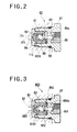
- a throttle valve unit 80 is disposed between the outlet of the accumulator 70 and a coupling 97 for the piping 95. It is not preferable to provide the throttle valve unit 80 having a severe throttling function between the pump 10 and the accumulator 70 because loads applied to the pump 10 is increased.
- the coupling 97 for the piping 95 is threadedly engaged with the connection area 11c on the housing 11 side and retains a seal ring 98.
- a piston case 81 is disposed within the connection area 11c on the inner side of the foremost end of the coupling 97.
- a generally glass-shaped piston 82 is disposed within the piston case 81. Under the influence of the force of the spring 83, the piston 82, this being a movable member, is normally brought into abutment with a bottom portion of the piston case 81 at its head portion where a notched passage 84 is present.
- the force of the spring 83 is set higher than the pulsation pressure.
- a valve opening pressure i.e., pressure for canceling the throttling function
- the valve opening pressure of the throttle valve unit 80 is set slightly higher than the pulsation pressure.
- the pulsation pressure attributable to the operation of the pump 10 is in a corresponding relation with the change in quantity of the liquid (or flow rate) discharged from the pump 10.
- a resin plate 85 with a slit 85s functions as a spring retainer for retaining one end of the spring 83 and also as a cushion member for the piston 82.
- the throttle valve 80 When the liquid-operated booster 90 adjacent to the piping 95 is abruptly actuated or the like, the throttle valve 80 thus constructed is in a position of Fig. 2 and effects the prescribed throttling function until the pressure differential or flow rate between the accumulator 70 side and the liquid-operated booster 90 reaches a predetermined value. More specifically, the pressurized liquid within the accumulation chamber 73b of the accumulator 70 reaches the inside of the piston case 81 via the outlet passage 64o at the outer periphery of the tubular member 64, a through-hole 11t formed in the housing 11, and then via a through-hole 81t formed in the bottom portion of the piston case 81. However, the piston 82 blocks a communication hole 810t at one side of the piston case 81.
- This tiny gap 88 has a throttling function equivalent to a tiny hole or aperture having a diameter of 0.01 mm order (for example, a tiny hole or aperture having a diameter of approximately 0.05 mm).
- the piston 82 moves toward the resin plate 85 side to open the communication hole 810t.
- the communication hole 810t communicates the interior of the piston case 81 with a sufficiently large passage formed between the outer periphery of the piston case 81 and the inner periphery of the coupling 97.
- the throttle valve unit 80 slightly delays the flow of the pressurized liquid from the accumulator 70 to the liquid-operated booster 90 by the throttling function for the first increment of time, and restrains the flow rate at the valve portion of the booster 90.
- this throttling function which is exhibited by the throttle valve unit 80, is also very effective for preventing the remaining pulsation.
- Fig. 3 shows another example of a throttle valve unit 800 having a tiny hole or aperture of a diameter of approximately 0.05 mm as a throttle.
- a tiny hole or aperture 880 formed in the piston 82 is employed as a throttle, and a ring member 850 with a slit 850s, which is formed of a rubber 851 and a metal piece 852 integrally molded, is employed as a spring retainer for retaining one end of the spring 83.
- All the remaining construction of the throttle valve unit 800 is the same as that of Fig. 2, and therefore the operation thereof is likewise the same.
- the system can be made simple in structure and the piping 95 can effectively be prevented from being vibrated by pulsation pressure.
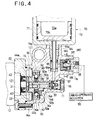
- Fig. 4 like Fig. 1, depicts the overall construction of the liquid pressure source unit, showing the positional relationship among its component parts. Since many parts of the second embodiment shown in Fig. 4 are identical with those of Fig. 1, the identical parts are denoted by identical reference numerals, respectively, and description thereof is omitted.
- this second embodiment there is employed a cancellation means for canceling the throttling function of a throttle valve unit 180 (280) when the pressure accumulated within the accumulator 70 is equal to or below a predetermined value. Consequently, in the second embodiment, the throttle valve unit and the cancellation means related thereto are different from those of the first embodiment. Therefore, these different portions will be described in greater detail.
- the coupling 97 for the piping 95 is threadedly engaged with the connection area 11c of the housing 11 side.
- a stepped piston 181 is disposed within the connection area 11c on the inner side of the foremost end of the coupling 97.
- the first piston 181 has an enlarged diameter portion 181a and a reduced diameter portion 181b. Seal rings 182a and 182b are retained respectively on the outer periphery of the enlarged and reduced diameter portions 181a and 181b.
- the enlarged diameter portion 181a is fitted into an internal bore of the connection area 11c, while the reduced diameter portion 181b is fitted to an inner periphery of the coupling 97.
- the throttle valve unit 180 When the pressure is not accumulated within the accumulator 70 and therefore the throttle valve unit 180 is in a non-operating condition, one end of the large diameter portion 181a of the first piston 181 is in abutment with the bottom portion of the connection area 11c under the influence of the force of the spring 183 (Fig. 4).
- the first piston 180 can move toward the piping 95 side because force generated owing to difference in pressure receiving area between the enlarged diameter portion 181a and the reduced diameter portion 181b overcomes the force of the spring 183 (Fig. 5).
- An axially extending groove 184 is formed in the inner periphery of the first piston 181, and a second piston 185 is disposed within a bore defined by the inner periphery where the groove 184 is formed (also see Fig. 6).
- the second piston 185 is urged against the bottom portion of the connection area llc by another spring 187 which serves a resin plate 186 as a spring retainer for retaining one end of the spring 187 as in the case with the above-mentioned spring 183, such that a head portion 185h having a reduced diameter is in abutment with the bottom portion of the connection area 11c.
- the first and second pistons 181 and 185 are, in mutual cooperation, capable of forming a first state where a throttle between the two pistons 181 and 185 is canceled as shown in Fig. 4, and a second state where a throttle S is formed between the two pistons 181 and 185 as shown in Fig. 5.
- the states in that the throttle is canceled by sealingly contained gas pressure of 40 kgf/cm 2 for pre-load, and the throttle S is effectively maintained by gas pressure higher than that. Since the throttle is canceled when the aforementioned deaeration or deoil operation is to be operated, these operations can be effected without any adverse affection from the throttling function.
- a communication passage (bypass passage) 500 for use of a bypass having a larger flow area than a throttle passage of the throttle valve unit 280, and an opening/closing piston 600 for opening and closing the bypass passage 500.
- a coupling 297 for the piping 95 is threadedly engaged with the connection area 11c of the housing 11 side and retains a seal ring 298.
- a piston case 281 is disposed at an inner side of a foremost end of the coupling 297.
- a movable glass-like piston 285 is disposed within the piston case 281.
- a resin plate 286 with a slit 286s functions as a spring retainer for retaining one end of the spring 287 and also as a cushion member for the piston 285.
- the bypass passage 500 communicates an inlet side of the throttle valve unit 280 with an outlet side thereof (i.e., the accumulator 70 side with the coupling 297 side).
- the bypass passage 500 includes, in addition to a T-shaped passage 501 formed within the opening/closing piston 600, a slant passage 502 for communicating one side where the opening/closing piston 600 is present with another side where the throttle valve unit 280 is present, and a through-hole 503 formed in the coupling 297.
- the opening/closing piston 600 ensures or permits a communication between the T-shaped passage 501 and the slant passage 502 until the pressure value accumulated within the accumulator 70 reaches a pre-load value.
- the force generated by the pressurized liquid owing to the pressure accumulated within the accumulator 70 overcomes the force of the spring 607.
- the opening/closing piston 600 is moved to cut off the communication between the T-shaped passage 501 and the slant passage 502.
- the throttling function owing to the throttle S becomes ineffective until a predetermined pressure is accumulated within the accumulator 70.
- a means for opening and closing a bypass passage 3500 has a different construction from that of the second example while the same throttle valve unit as that of the second example is used. More specifically, a spring-loaded sleeve-shaped member 3600 is disposed at a lower end portion of a tubular member 364 which is disposed at the inlet/outlet portion of the accumulator 70. Under the effect of the spring 4607, the sleeve-like member 3600 is moved in unison with the tubular member 364. Also, under the effect of the same spring 3607, the tubular member 364 is moved in unison with the piston 72 of the accumulator 70.
- the sleeve-like member 3600 moves in accordance with the movement of the piston 72 of the accumulator 70.
- the sleeve-like member 3600 has a communication hole 3605 for communicating the inside with the outside.
- this communication hole 3605 as well as the bypass passage 3500, the inlet side of the throttle valve unit 280 can communicate with the outlet side thereof.
- the sleeve-like member 3600 cuts off the communication between the communication hole 3605 and the bypass passage 3500 in response to the movement of the piston 72.
- a notch 372a is formed in that surface of the piston 72 where the tubular member 364 contacts.
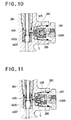
- a means for opening and closing a bypass passage 4500 has a different construction from those of the second and third examples while the same throttle valve unit as those of the second and third examples are used.
- the opening/closing means of the fourth example is the same as the third example in the respect that it is operated in accordance with the stroke of the piston 72 of the accumulator 70.
- the bypass passage 4500 is disposed at the inside of the throttle valve unit 280, and a bypass rod 400 is disposed at a head portion of the throttle valve unit 280.
- a communication hole 405 portion formed therein constitutes a part of the bypass passage 4500, and the bypass passage 4500 is opened and closed by the movement of bypass rod 400 itself.
- a sleeve-like member 4600 is provided at a lower end of the tubular member 364 at the inlet/outlet portion of the accumulator 70. The sleeve-like member 4600 is moved in unison with the tubular member 364 under the effect of a spring 3607 loaded in the member 4600. Also, the sleeve-like member 4600 is moved in accordance with the stroke of the piston 72 of the accumulator 70. This sleeve-like member 4600 functions as a cam relative to the bypass passage 400.
- the bypass rod 400 is moved in accordance with the stroke of the piston 72 to close the communication hole 405 and also to close the bypass passage 4500 as shown in Fig. 11.
- the throttle S becomes effective and the throttle valve unit 280 exhibits its function for reducing the pulsation, etc.
- a sliding resistance of the bypass rod 400 is preferably set somewhat large relative to the piston 285 within the throttle valve unit 280.
Landscapes
- Engineering & Computer Science (AREA)
- Mechanical Engineering (AREA)
- Physics & Mathematics (AREA)
- Fluid Mechanics (AREA)
- General Engineering & Computer Science (AREA)
- Transportation (AREA)
- Valves And Accessory Devices For Braking Systems (AREA)
- Braking Systems And Boosters (AREA)
Claims (9)
- Flüssigkeitsdrucksystem, das einen flüssigkeitsbetätigten Verstärker (90) umfasst, der eine hydraulische Druckpumpe (10) umfasst, die hydraulische Flüssigkeit ansaugen kann, und Druckflüssigkeit entlassen kann, und ein Sammelgerät (70), um die von der hydraulischen Druckpumpe (10) entlassene Druckflüssigkeit zu sammeln, wobei die in dem Sammelgerät (70) gesammelte Druckflüssigkeit an den flüssigkeitsbetätigten Verstärker (90) geliefert wird, dadurch gekennzeichnet, dass eine Drosselventileinheit (80, 800, 180, 280) zwischen dem Sammelgerät (70) und dem flüssigkeitsbetätigten Verstärker (90) vorgesehen ist, und ein Strömungsgebiet stark verringern kann, bis ein Druckdifferential oder eine Strömungsgeschwindigkeit einen vorbestimmten Wert erreicht, wobei die Drosselventileinheit (80, 800, 180, 280) eine Drosselfunktion hat, die gleich einem Loch in der Grössenordnung von einem Durchmesser von 0,01 mm ist, was dazu dient, Rauschen in dem Verstärker zu verringern, wobei die Drosselventileinheit (80, 800, 180, 280) ein Glied (82, 185, 285) hat, das zwischen einer ersten Stellung, in der die Drossel (S) ein Strömungsgebiet in Übereinstimmung mit Anderung des Druckdifferentials oder der Strömungsgeschwindigkeit hat, und einer zweiten Stellung, um die Drossel (S) aufzuheben, bewegt werden kann.
- Flüssigkeitsdrucksystem nach Anspruch 1, dadurch gekennzeichnet, dass das Sammelgerät (70) mit der hydraulischen Druckpumpe (10) integral ist und durch ein Rohrleitungssystem (95) an den flüssigkeitsbetätigten Verstärker (90) angeschlossen ist, und die Drosselventileinheit (80, 800, 180, 280) auf der Seite des Rohrleitungssystem (95) vorgesehen ist, die an das Sammelgerät (70) angeschlossen ist.
- Flüssigkeitsdrucksystem nach Anspruch 1, das weiterhin ein rohrförmiges Glied (64) umfasst, das an einem Einlassteil des Sammelgeräts (70) angeordnet ist, in das Druckflüssigkeit von der hydraulischen Druckpumpe (10) strömt, wobei ein Raum in dem Einlassteil durch das rohrförmige Glied (64) in einen inneren Raum (64i), der von einer inneren Peripherie des rohrförmigen Glieds (64) definiert ist, und einen äusseren Raum (640), der von einer äusseren Peripherie des rohrförmigen Glieds (64) definiert ist, aufgeteilt ist, wobei der innere oder der äussere Raum als ein Einlassdurchgang in das Sammelgerät (70) dient, und der andere des inneren und äusseren Raums als ein Auslassdurchgang von dem Sammelgerät zum flüssigkeitsbetätigten Verstärker (90) dient.
- Flüssigkeitsdrucksystem nach Anspruch 3, dadurch gekennzeichnet, dass der innere Raum (64i) als Einlassdurchgang dient, und der äussere Raum (640) als Auslassdurchgang dient.
- Flüssigkeitsdrucksystem nach Anspruch 2, dadurch gekennzeichnet, dass die Drosselventileinheit (80, 800, 180, 280) in dem Gehäuse der hydraulischen Druckpumpe (10) angeordnet ist und an das Rohrleitungssystem (95) angeschlossen ist.
- Flüssigkeitsdrucksystem nach Anspruch 5, dadurch gekennzeichnet, dass die Drosselventileinheit (80, 800, 180, 280) einen Kolbenkasten (81, 181, 281) umfasst, einen Kolben (82, 185, 285), der in dem Kolbenkasten (81, 181, 281) bewegt werden kann, und eine Feder (83, 187, 287), um den Kolben (82, 185, 285) zu spannen.
- Flüssigkeitsdrucksystem nach Anspruch 1, dadurch gekennzeichnet, dass das Sammelgerät (70) die Druckflüssigkeit, die in einem vorbestimmten Druckbereich von der hydraulischen Druckpumpe (10) entlassen wird, sammeln kann, und das weiterhin ein Aufhebungsmittel umfasst, um eine Drosselfunktion der Drosselventileinheit (80, 800, 180, 280) aufzuheben, wenn die in dem Sammelgerät (70) gesammelte Druckflüssigkeit auf einen Stand fällt, der gleich oder geringer als der tiefste Druck des vorbestimmten Druckbereichs ist.
- Flüssigkeitsdrucksystem nach Anspruch 7, dadurch gekennzeichnet, dass das Aufhebungsmittel einen Kolben (181, 600) hat, der unter dem Einfluss von Druck von dem Sammelgerät (70) in Übereinstimmung mit der Druckänderung bewegt werden kann, und einen Verbindungsdurchgang, (184, 500), um die Einlassseite der Drosselventileinheit (80, 800, 180, 280) mit der Auslassseite davon mit einem Strömungsgebiet grösser als dem Strömungsgebiet der Drosselventileinheit zu verbinden, wobei der Verbindungsdurchgang (184, 500) fähig ist, sich in Übereinstimmung mit einer Bewegung des Kolbens (181, 600) zu öffnen und zu schliessen.
- Flüssigkeitsdrucksystem nach Anspruch 8, dadurch gekennzeichnet, dass das Sammelgerät (70) eine bewegbare Wand (72) hat, um eine Drucksammelkammer (73b) und eine Vorbelastungskammer (73a) zu teilen, und das Aufhebungsmittel ein bewegbares Glied (3600, 4600) hat, das in mechanischem Eingriff betrieblich an die bewegbare Wand (72) angeschlossen ist, und einen Verbindungsdurchgang (3500, 4500), um die Einlassseite der Drosselventileinheit (80, 800, 180, 280) mit der Auslassseite davon mit einen Strömungsgebiet grösser als dem Strömungsgebiet der Drosselventileinheit zu verbinden, wobei der Verbindungsdurchgang (3500, 4500) in Übereinstimmung mit einer Bewegung des bewegbaren Glieds (3600, 4600) geöffnet und geschlossen werden kann.
Applications Claiming Priority (4)
| Application Number | Priority Date | Filing Date | Title |
|---|---|---|---|
| JP32480192A JPH06144212A (ja) | 1992-11-09 | 1992-11-09 | 動力圧型作動補助装置 |
| JP324801/92 | 1992-11-09 | ||
| JP35323792A JPH06171493A (ja) | 1992-12-12 | 1992-12-12 | 液圧源装置 |
| JP353237/92 | 1992-12-12 |
Publications (2)
| Publication Number | Publication Date |
|---|---|
| EP0597610A1 EP0597610A1 (de) | 1994-05-18 |
| EP0597610B1 true EP0597610B1 (de) | 1997-03-05 |
Family
ID=26571621
Family Applications (1)
| Application Number | Title | Priority Date | Filing Date |
|---|---|---|---|
| EP93308644A Expired - Lifetime EP0597610B1 (de) | 1992-11-09 | 1993-10-29 | Flüssigkeitsdruck-Quelle für Flüssigkeitsbetätigten Verstärker |
Country Status (3)
| Country | Link |
|---|---|
| US (1) | US5379593A (de) |
| EP (1) | EP0597610B1 (de) |
| DE (1) | DE69308478T2 (de) |
Families Citing this family (7)
| Publication number | Priority date | Publication date | Assignee | Title |
|---|---|---|---|---|
| US5620028A (en) * | 1995-03-20 | 1997-04-15 | General Motors Corporation | Brake Module with integrated accumulator |
| DE202005021720U1 (de) * | 2004-07-13 | 2009-09-10 | Waters Investments Ltd., New Castle | Hochdruckpumpen-Steuereinheit |
| GB2486062A (en) * | 2010-11-30 | 2012-06-06 | Bosch Gmbh Robert | Brake having valve control to reduce pulsation flow of a piston pump |
| DE102010062188A1 (de) * | 2010-11-30 | 2012-05-31 | Robert Bosch Gmbh | Verfahren zum Betrieb einer hydraulischen Fahrzeugbremsanlage |
| DE102011078250A1 (de) * | 2011-06-29 | 2013-01-03 | Continental Teves Ag & Co. Ohg | Ventilbaugruppe |
| KR102443094B1 (ko) * | 2015-10-05 | 2022-09-14 | 주식회사 만도 | 유압 브레이크 시스템 |
| CN210422911U (zh) * | 2019-07-16 | 2020-04-28 | 深圳华星恒泰泵阀有限公司 | 一种微型电磁水泵 |
Family Cites Families (18)
| Publication number | Priority date | Publication date | Assignee | Title |
|---|---|---|---|---|
| CA722520A (en) * | 1965-11-30 | The Bendix Corporation | Full power hydraulic servomotor | |
| DE2643860A1 (de) * | 1976-09-29 | 1978-03-30 | Bosch Gmbh Robert | Hydraulisches system |
| SU717410A1 (ru) * | 1977-01-03 | 1980-02-25 | Всесоюзный Научно-Исследовательский И Проектно-Конструкторский Институт Промышленных Гидроприводов И Гидроавтоматики Вниигидропривод | Пневмогидропреобразователь |
| JPS6025298B2 (ja) * | 1979-01-17 | 1985-06-17 | 日産自動車株式会社 | 油圧ブ−スタのリリ−フバルブ機構 |
| DE3133111A1 (de) * | 1981-08-21 | 1983-04-14 | Robert Bosch Gmbh, 7000 Stuttgart | Druckbeschaffungseinrichtung |
| DE3215954A1 (de) * | 1982-04-29 | 1983-11-03 | Alfred Teves Gmbh, 6000 Frankfurt | Hydraulische bremsanlage |
| DE3230082A1 (de) * | 1982-08-13 | 1984-02-16 | Alfred Teves Gmbh, 6000 Frankfurt | Hydraulische bremsanlage |
| JPS60206762A (ja) * | 1984-03-30 | 1985-10-18 | Aisin Seiki Co Ltd | 液圧ブ−スタ |
| DE3627264C2 (de) * | 1986-08-12 | 1996-08-22 | Teves Gmbh Alfred | Hydraulische Kraftfahrzeug-Bremsanlage |
| DE3717547A1 (de) * | 1987-05-25 | 1988-12-15 | Teves Gmbh Alfred | Bremsbetaetigungsvorrichtung fuer kraftfahrzeuge |
| KR890000299A (ko) * | 1987-06-24 | 1989-03-13 | 나카하라 츠네오 | 유압부우스터 |
| JPH0771926B2 (ja) * | 1988-09-20 | 1995-08-02 | 株式会社ナブコ | アンチスキッドブレーキ装置 |
| DE58907004D1 (de) * | 1988-12-17 | 1994-03-24 | Teves Gmbh Alfred | Hydraulikpumpe. |
| DE3907969A1 (de) * | 1989-03-11 | 1990-09-13 | Bosch Gmbh Robert | Hydraulische hochdruckpumpe fuer eine bremsanlage eines fahrzeugs |
| DE3923282C2 (de) * | 1989-07-14 | 1998-04-30 | Bosch Gmbh Robert | Vorrichtung zur Dämpfung von Druckschwingungen |
| JPH03125664U (de) * | 1990-03-31 | 1991-12-18 | ||
| JPH03129785U (de) * | 1990-04-06 | 1991-12-26 | ||
| JPH0822667B2 (ja) * | 1991-03-26 | 1996-03-06 | 株式会社ナブコ | 液圧式倍力装置 |
-
1993
- 1993-10-26 US US08/143,454 patent/US5379593A/en not_active Expired - Fee Related
- 1993-10-29 DE DE69308478T patent/DE69308478T2/de not_active Expired - Fee Related
- 1993-10-29 EP EP93308644A patent/EP0597610B1/de not_active Expired - Lifetime
Also Published As
| Publication number | Publication date |
|---|---|
| DE69308478D1 (de) | 1997-04-10 |
| EP0597610A1 (de) | 1994-05-18 |
| DE69308478T2 (de) | 1997-06-12 |
| US5379593A (en) | 1995-01-10 |
Similar Documents
| Publication | Publication Date | Title |
|---|---|---|
| CA1289598C (en) | Hydraulic pump with integrated sump and accumulator | |
| US5213482A (en) | Hydraulic radial-type piston pump | |
| US7004733B2 (en) | Piston pump | |
| KR100400798B1 (ko) | 액압 어큐뮬레이터 | |
| EP0956985B1 (de) | Verfahren und Vorrichtung zur Unterdrückung von Resonanz | |
| JPH03502829A (ja) | 液圧ポンプ | |
| EP0597610B1 (de) | Flüssigkeitsdruck-Quelle für Flüssigkeitsbetätigten Verstärker | |
| US5852931A (en) | Automatic transmission with a positive-displacement pump | |
| JP3184523B2 (ja) | 自動車用液圧ブレーキシステムの制動圧制御装置 | |
| JP3443427B2 (ja) | 油圧制御回路用アキュムレータ | |
| JP2000345954A (ja) | ラジアルピストンポンプ | |
| US20230256946A1 (en) | Hydraulic pressure control unit | |
| JPH06144212A (ja) | 動力圧型作動補助装置 | |
| KR100550947B1 (ko) | 브레이크 시스템용 펌프 | |
| US5971727A (en) | High-pressure hydraulic pump with improved performance | |
| KR102478710B1 (ko) | 브레이크 액압 제어 장치 | |
| KR100543871B1 (ko) | 안티록 브레이크 시스템용 펌프 | |
| JP7352710B1 (ja) | シリンダ装置 | |
| US5944491A (en) | Piston-type compressor with improved shock absorption during start up | |
| JPH06171493A (ja) | 液圧源装置 | |
| JP2000186701A (ja) | ピストン式アキュームレータ | |
| WO1996028659A1 (en) | Piston pump | |
| JP3472373B2 (ja) | プランジャポンプ | |
| JP2002362344A (ja) | ピストン型リザーバおよび車両用ブレーキ液圧制御ユニット | |
| CA2232955C (en) | High-pressure hydraulic pump with improved performance |
Legal Events
| Date | Code | Title | Description |
|---|---|---|---|
| PUAI | Public reference made under article 153(3) epc to a published international application that has entered the european phase |
Free format text: ORIGINAL CODE: 0009012 |
|
| AK | Designated contracting states |
Kind code of ref document: A1 Designated state(s): DE FR GB |
|
| 17P | Request for examination filed |
Effective date: 19940624 |
|
| 17Q | First examination report despatched |
Effective date: 19941021 |
|
| GRAG | Despatch of communication of intention to grant |
Free format text: ORIGINAL CODE: EPIDOS AGRA |
|
| GRAH | Despatch of communication of intention to grant a patent |
Free format text: ORIGINAL CODE: EPIDOS IGRA |
|
| GRAH | Despatch of communication of intention to grant a patent |
Free format text: ORIGINAL CODE: EPIDOS IGRA |
|
| GRAA | (expected) grant |
Free format text: ORIGINAL CODE: 0009210 |
|
| AK | Designated contracting states |
Kind code of ref document: B1 Designated state(s): DE FR GB |
|
| REF | Corresponds to: |
Ref document number: 69308478 Country of ref document: DE Date of ref document: 19970410 |
|
| ET | Fr: translation filed | ||
| PGFP | Annual fee paid to national office [announced via postgrant information from national office to epo] |
Ref country code: FR Payment date: 19971009 Year of fee payment: 5 |
|
| PGFP | Annual fee paid to national office [announced via postgrant information from national office to epo] |
Ref country code: GB Payment date: 19971020 Year of fee payment: 5 |
|
| PGFP | Annual fee paid to national office [announced via postgrant information from national office to epo] |
Ref country code: DE Payment date: 19971110 Year of fee payment: 5 |
|
| PLBE | No opposition filed within time limit |
Free format text: ORIGINAL CODE: 0009261 |
|
| 26N | No opposition filed | ||
| PG25 | Lapsed in a contracting state [announced via postgrant information from national office to epo] |
Ref country code: GB Free format text: LAPSE BECAUSE OF NON-PAYMENT OF DUE FEES Effective date: 19981029 |
|
| GBPC | Gb: european patent ceased through non-payment of renewal fee |
Effective date: 19981029 |
|
| PG25 | Lapsed in a contracting state [announced via postgrant information from national office to epo] |
Ref country code: FR Free format text: LAPSE BECAUSE OF NON-PAYMENT OF DUE FEES Effective date: 19990630 |
|
| REG | Reference to a national code |
Ref country code: FR Ref legal event code: ST |
|
| PG25 | Lapsed in a contracting state [announced via postgrant information from national office to epo] |
Ref country code: DE Free format text: LAPSE BECAUSE OF NON-PAYMENT OF DUE FEES Effective date: 19990803 |