EP0597489A1 - Elément sanitaire actionné par une pompe - Google Patents
Elément sanitaire actionné par une pompe Download PDFInfo
- Publication number
- EP0597489A1 EP0597489A1 EP93118364A EP93118364A EP0597489A1 EP 0597489 A1 EP0597489 A1 EP 0597489A1 EP 93118364 A EP93118364 A EP 93118364A EP 93118364 A EP93118364 A EP 93118364A EP 0597489 A1 EP0597489 A1 EP 0597489A1
- Authority
- EP
- European Patent Office
- Prior art keywords
- pump
- toilet
- water
- flush water
- reservoir tank
- Prior art date
- Legal status (The legal status is an assumption and is not a legal conclusion. Google has not performed a legal analysis and makes no representation as to the accuracy of the status listed.)
- Granted
Links
Images


Classifications
-
- E—FIXED CONSTRUCTIONS
- E03—WATER SUPPLY; SEWERAGE
- E03D—WATER-CLOSETS OR URINALS WITH FLUSHING DEVICES; FLUSHING VALVES THEREFOR
- E03D3/00—Flushing devices operated by pressure of the water supply system flushing valves not connected to the water-supply main, also if air is blown in the water seal for a quick flushing
- E03D3/12—Flushing devices discharging variable quantities of water
-
- E—FIXED CONSTRUCTIONS
- E03—WATER SUPPLY; SEWERAGE
- E03D—WATER-CLOSETS OR URINALS WITH FLUSHING DEVICES; FLUSHING VALVES THEREFOR
- E03D5/00—Special constructions of flushing devices, e.g. closed flushing system
- E03D5/10—Special constructions of flushing devices, e.g. closed flushing system operated electrically, e.g. by a photo-cell; also combined with devices for opening or closing shutters in the bowl outlet and/or with devices for raising/or lowering seat and cover and/or for swiveling the bowl
-
- E—FIXED CONSTRUCTIONS
- E03—WATER SUPPLY; SEWERAGE
- E03D—WATER-CLOSETS OR URINALS WITH FLUSHING DEVICES; FLUSHING VALVES THEREFOR
- E03D1/00—Water flushing devices with cisterns ; Setting up a range of flushing devices or water-closets; Combinations of several flushing devices
- E03D1/02—High-level flushing systems
- E03D1/14—Cisterns discharging variable quantities of water also cisterns with bell siphons in combination with flushing valves
-
- E—FIXED CONSTRUCTIONS
- E03—WATER SUPPLY; SEWERAGE
- E03D—WATER-CLOSETS OR URINALS WITH FLUSHING DEVICES; FLUSHING VALVES THEREFOR
- E03D5/00—Special constructions of flushing devices, e.g. closed flushing system
- E03D5/01—Special constructions of flushing devices, e.g. closed flushing system using flushing pumps
Definitions
- This invention relates to water saving plumbing fixtures. More particularly, it relates to improved means for using a pump to assist in the operation of plumbing fixtures such as toilets and urinals.
- Gravity feed toilets of the type having a reservoir at least partially above the level of a toilet bowl have in the past typically had a water capacity of 3 or more gallons for flushing the toilet.
- the efficiency of these toilets have been improved such that in many cases 1.6 gallons of water is sufficient to clean the bowl.
- double flushing may still be needed to completely clean the bowl.
- additional water savings could be effected if these toilets could be made even more efficient during normal flushes and if less water could be employed to flush when only urine and toilet tissue are in the bowl.
- the invention provides a plumbing fixture for receiving flushable waste comprising at least one receptacle for receiving the waste, a reservoir tank for storing a volume of flush water, a pump motor and pump (both positioned in the reservoir tank), the inlet of the pump being in communication with the interior of the reservoir tank, a conduit connected between a pump outlet and the receptacle, and control means selectively and operatively connected to the motor to operate the pump for one period of time to deliver a quantity of flush water to the pump outlet.
- the pump means is positioned either inside or outside the reservoir tank and the control means is selectively and operatively connected to the motor to the pump means to operate the pump for at least one other period of time to deliver at least one other quantity of flush water to the receptacle.
- a refill valve is operatively connected to an intake conduit, and a tube is connected between the refill valve and the rim of a toilet bowl.
- control means which include a time delay means to prevent activation of the pump and overflow of the toilet bowl.
- a fluid passage means disposed through the tank wall and positioned below the motor and electrical connection to the motor.
- a receptacle for storing a fluid such as a cleaning fluid and an additional pump means for pumping such a fluid into the toilet bowl to clean the toilet bowl.
- overflow prevention means for both the reservoir tank and the toilet bowl.
- an electrically operated fail-safe valve is connected to the supply conduit to shut off the water supply in the instance where there is a leaky supply valve.
- an overflow sensor connected to a pump motor to pump excess water from the tank.
- first and second conduits connected between the pump outlet and the basin and the rim.
- Control means connected to the motor and pump sequentially delivers a volume of flush water to the rim, a volume of flush water to the bowl either alternatively, or simultaneously, and in selective sequences.
- the objects of the invention therefore include:
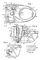
- a toilet generally 10 having a basin or bowl portion 12 with a hollow rim 14.
- a "reservoir” 16 is in the form of tank 17.
- a pump 18 Positioned in the tank 17 is a pump 18 which is of the sump type. It is supported in the reservoir by vibration absorbing feet 19.
- Pump unit generally 43 includes a pump 18 driven by an electric motor 20 with electric power being supplied by electrical cord 21.
- the motor 20 drives the pump 18 by means of a sealed and enclosed magnetic drive which is explained below in more detail in conjunction with Fig. 13. It should be noted that one surprising aspect of the invention is positioning an electrical motor in the toilet water tank.
- An outlet conduit 27 delivers water to the lower portion of bowl 12, such as through jet channel 28 (See Fig. 4) attached via connector 68.
- a smaller conduit 30 delivers water to the rim 14 through the channel 32.
- a float valve assembly 37 includes a float 39 which operates a valve (not shown) in pipe 40 by means of rod 42 and lever arm 44. Float 39 is guided by the guide member 45. Water that passes the inlet valve enters the reservoir through the inlet valve hush tube 47. There is also a bypass tube 50 connected to the float valve assembly to deliver a small amount of water to the rim 14 whenever the float valve is in an open condition.
- dam member 69 which is positioned adjacent the return passage 33 and inside the tank 17. This serves to raise the water level in the tank 17 or the bowl portion 12 before overflowing into the other occurs.
- a rim vent hole 73 is also provided to facilitate water flow, as best shown in Figs. 3 and 6.
- openings 52 there are several openings 52 extending through the back wall 11 of the tank 17.
- the purpose of the openings 52 is that if return passage 33 is blocked to allow overflow water from tank 17 to spill out of the tank.
- the openings 52 provide a fluid spill passage and are positioned in the tank a distance above the bottom so that overflow water will escape prior to contact with the electrical connection from cord 21 with the motor 20 and are positioned below the point where water could enter the motor.
- the position of this connection is indicated in Fig. 2.
- the openings 52 also prevent contaminated water from rising high enough in the tank to contact intake water in pipe 40.
- Figs. 8-11 represent alternative embodiments generally 10A.
- the same or similar components are designated with the same reference numerals as for the first embodiment except followed by the letter "A".
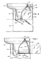
- One of the differences between the two embodiments is the placement of the reservoir 16A below the bowl portion 12A and accordingly the water level in the reservoir 16A below that of the bowl portion 12A.
- a support post 15A for the bowl portion 12A is provided as well as a surrounding housing 22A extending along the sides and back of the bowl portion 12A.
- a receptacle 24A which contains a cleaning fluid for cleansing the bowl portion 12A.
- the cleaning fluid is pumped from the receptacle 24A by means of the conduit 53A connected to the inlet side of the pump 54A driven by the motor 56A.
- a second conduit 57A extends from the outlet side of the pump 54A to the rim 14A of the bowl portion 12A where it is connected to inlet tube 55A.
- Fig. 11 shows an alternative placement of the receptacle 24A outside of the surrounding housing 22A.
- Figs. 9 and 10 particularly illustrate the supply of water to the reservoir 16A, as well as to the rim 14A and bowl portion 12A.
- the pump 18A and motor 20A are located in the reservoir 16A.
- Water enters through the float valve assembly 37A and is delivered to the reservoir 16A by the outlet pipe 47A.
- inlet water is supplied to the float valve assembly 37A by the supply line 59A.
- the inlet water is supplied through the back of housing 22A through line 59A and is controlled by a normally closed solenoid which opens, when electrically activated, the valve 60A.
- Pump 18A supplies water to the bowl portion 12A by means of the conduit 27A which is connected to conduits 27A' and 27A" as well as to manifold 25A. It also supplies water to the rim 14A by the conduit 30A connected to the manifold 25A.
- a solenoid diaphragm valve 62A connected to conduit 27A'. It is operated by a pilot 63A and is maintained in a closed position until activated to supply water to the bowl portion 12A.
- a water level sensor device generally 65A which includes a float 66A mounted on guide rod 64A having an electrical contact cap 67A on the end thereof. Contact by the float 66A with the cap 67A will send an electrical signal to motor 20A to operate pump 18A and thereby determine the maximum level of water 26A in reservoir 16A.
- Guide rod 64A is supported on bracket 61A which in turn is adjustably connected to support rod 51A.
- a trap- way 49A communicating with the typical outlet drain 58A is also shown.
- Fig. 12 illustrates yet another alternative embodiment (generally 70B).
- the pump 18B and the motor 20B are located outside of a plumbing fixture such as a wall hung toilet 10B.
- flush water would be contained in reservoir 16B and is pumped from the reservoir 16B by means of the intake conduit 71 B and the output conduit 72B. Water is diverted to the toilet 10B and/or the urinal 74B through the diverter valve 75B.
- the volume of water pumped to the toilet 10B will be 1.6 gallons or less, whereas that normally delivered to the urinal 74B would be 1.0 gallon or less.
- the volume of water delivered to the toilet 10B and the urinal 74B can be controlled by a timing circuit as is explained later in conjunction with Figs. 14 and 16A and B.
- Fig. 13 shows in more detail a pump 18 which is driven by the motor 20. Both the motor 20 and the pump 18 are enclosed in sealed housings 29 and 31.
- An electric motor 13 drives rotor 34 having magnets 36 which attract magnets 38 carried by the pump rotor 41. This effects a pumping action causing water to enter at entrance 23 and to exit from manifold 25 (See Fig. 2). It should be noted that placement of the magnets 36 and 38 in their respective plastic housings effects a seal between the rotors 34 and 41, thus reducing the chance of an electrical short into the reservoir water.
- Foot members 46 provide for suitable spacing of entrance 23 from the bottom of reservoir 16 or 16A (See Fig. 2 or Fig. 3).
- a support member 48 positions the electric motor 13 at a predetermined distance above the floor of motor housing 29.
- FIGs. 14-17C illustrate electrical controls for the previously described embodiments.
- a microprocessor 80 is programmed to effect the desired and described functions which in the instance of embodiment 10A include a short flush function, a long flush function (which can be activated by the seat cover being closed), as well as a special bowl cleaner flush. These functions can be initiated by the respective switch buttons 81, 82 and 83 which preferably are of the touch type.
- a switch of this kind would be a membrane switch which would have a long flush and a short flush function in the same switch housing.
- a monostable multivibrator 85 which is commonly known as a "one-shot".
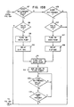
- Figs. 15A and B represent the flow diagram for embodiment shown in Figs. 1-7.
- the first step in the operation of the pump toilet 10 after the start 89 is the decision step 90 as to whether a switch has been activated such as by a key or push button. If a key is not activated, a background timer is updated at 91 and at 92. It is checked to see if it has a designated number of units. If it does, it is reset at 93 and a flush timer is looked at at 94 to determine if it equals 0 seconds. If it does not, it is decremented at 95.
- This background timer will operate in conjunction with the flush timer in a manner to be explained in conjunction with the actuation of the later described activation of the long and short keys at 97 and 105 and the timing of the main pump 18.
- the flush timer is checked to see if it is at greater than 30 seconds. If it is not, this allows activation of either the long or short keys at 97 or 105.
- main pump 18 is turned on at step 99 after a valid input check at 98. This immediately delivers water to the rim portion 14 by way of conduit 30, as well as to the jet in the bowl portion 12 through conduit 25. After a delay of 3.17 seconds as indicated at step 100, the pump 18 is turned off at step 101. This will deliver 1.6 gallons of water and would normally be used to flush fecal matter.
- step 102 there is added 60 seconds to the flush timer after which there is a determination made at 103 and 104 as to whether the long or short key has been pressed before another flush cycle is initiated.
- the short flush key 105 is activated such as by switch 81.
- the pump 18 is activated at 107, and it is operated for 2.07 seconds as indicated at 108. It is turned off at 101 after delivering 1.0 gallon of water. This short flush would normally be used to flush urine and paper. Again 60 seconds would be added to the flush timer as indicated at 102.
- the background and flush timers are programmed in conjunction with steps 96 and 102 so that there are two delay features.
- the first involves a situation where a second flush occurs more than 30 seconds but less than 60 seconds after the first flush. It will be recognized that there is always a 30 second delay between flushes in order to refill the tank 17. In this situation, the toilet may be flushed a second time after the initial 30 second delay, but if this is done, it may then not be flushed a third time until there has been a maximum of 90 seconds from the first flush and add 60 seconds to each flush thereafter.
- the second alternative involves a situation where the second flush does not occur within 60 seconds of the first flush or 90 seconds after any following flushes. In this case, the background timer automatically resets and the toilet can be flushed again with no limit other than the 30 seconds required to fill the tank. In essence, this means that the toilet may be flushed every 60 seconds without being limited, as in the first case.
- Figs. 16A and B represent the flow diagram for embodiment shown in Fig. 12. It will be seen that steps 89-96 are the same as previously described in conjunction with Fig. 15A. If the toilet flush key 110 is selected, which would be activated such as by switch 82, then the same steps 98-102 would be followed as previously explained in conjunction with Fig. 15B. Similarly, the same determinations of the status of the toilet and urinal flush keys are made at 116 and 117. In the event the seat flush feature is activated such as at 112 and by the lid closed switch 84, the same procedure will be followed as indicated at steps 98-102 for the long flush.
- a short flush cycle is initiated which is similar to steps 106-108 and 101 and 102 as described in conjunction with Fig. 15B.
- steps 106-108 and 101 and 102 as described in conjunction with Fig. 15B.
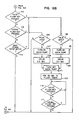
- Figs. 17A, B and C represent the flow diagrams for the embodiment shown in Figs. 8-10.
- the steps 89-96 are the same as previously described in conjunction with Figs. 15A and 16A except for step 122 where supply valve 60 is turned on. If the long flush key 97 is activated, then main pump 18A is turned on at step 99 after a valid input check at 98. This immediately delivers water to the rim portion 14A by way of conduit 30A.
- a seat activated function is also shown at step 136 in conjunction with long flush steps 98-101 as previously described.
- the short flush button 81 is activated to initiate the short flush as indicated at step 105.
- the subsequent steps 106-130 are essentially the same as indicated for the respective steps 98-126 except for step 108 where the pump is operated for 2.5 seconds rather than 3.5 seconds.
- step 131 which delivers a cleaning fluid to the rim portion 14A.
- the main pump 18A and the sanitary pump 54A are turned on at step 133.
- the main pump 18A and the sanitary pump 54A are turned off at step 134 after which there is a delay period of 60 seconds as shown at 135.
- a signal is sent to the microprocessor 80 from the level sensor 65A.
- This signal is shown as activated at 137 with the main pump 18A being turned on at 138 as well as the jet solenoid to pump water from the reservoir 16A and to the toilet 10A in order to prevent an overflow condition in the reservoir 16A should float valve assembly 37A malfunction.
- the main pump 18A and jet solenoid are turned off at 140. If the overflow feature has been active 3 times in 60 minutes as shown at 141, the supply valve 60A is turned off at 141 and a waiting period initiated at 143.
- An additional safety feature in conjunction with the microprocessor 80 is the closing of supply valve 60A in the event of electrical failure to the control circuit and pump 18A and the failure of float valve assembly 37A to close.
- our invention provides an improved toilet flushing system which utilizes a minimum of water for each function.
- the need for double flushing is reduced.
- preferred embodiments have been described above, it should be readily apparent to those skilled in the art from this disclosure that a number of modifications and changes may be made without departing from the spirit and scope of the invention.
- this system can be altered to deliver water only to the rim by eliminating the conduits 27, 27A, 27A' and 27A" to the bowl as well as the valve 62A.
- flush water delivery only to the bowl can be effected by the herein described system by elimination of the conduits 30 and 30A to the rim and valve 62A.
- Any combination of the delivery of flush water to the rim and/or bowl can be effected by suitable valving.
- a valve such as 62A can be placed in conduit 30A.
- a 3-way valve could be used in conjunction with conduits 27, 27A, 27A', 27A" and 30A.
- a long and short flush cycle have been described in conjunction with the previously disclosed embodiments. It should be understood that these two cycles can be employed independently of the bowl cleaner flush or the seat cover activation. In the same manner, a third longer flush cycle could be utilized with the long and short flush cycle as well as an intermediate one with varying quantities of flush water. Similarly, if desired, only a single flush cycle could be employed by eliminating one of the flush cycles and still operate the pump for a period of time to deliver a quantity of water from the reservoir tank to the toilet bowl. While the reservoir 16B and pump 18B have been described in conjunction with one toilet 10B and one urinal 74B, a multiplicity of these plumbing fixtures could be employed by interconnection with output conduits 73B and 74B. All of the flush cycles previously described in conjunction with embodiment 10A can be utilized with toilet 10B.
- the seat cover and sanitation functions could be eliminated and still accomplish the water saving feature.
- the overflow features could be eliminated and still accomplish the described water saver functions.
- the cleanser function could be automated such that the processor would count uses such that after a given number of uses of a toilet (e.g. thirty), the cleaning cycle would automatically occur. A long and short flush cycle have been effected by operating a pump motor for different time intervals. This could also be accomplished by running the pump motor at two different speeds as shown alternatively in dotted line in Fig. 15B.
Priority Applications (1)
| Application Number | Priority Date | Filing Date | Title |
|---|---|---|---|
| EP00122449A EP1069250B1 (fr) | 1992-11-13 | 1993-11-12 | Elément sanitaire actionné par une pompe |
Applications Claiming Priority (2)
| Application Number | Priority Date | Filing Date | Title |
|---|---|---|---|
| US976109 | 1992-11-13 | ||
| US07/976,109 US5305475A (en) | 1992-11-13 | 1992-11-13 | Pump operated plumbing fixture |
Related Child Applications (1)
| Application Number | Title | Priority Date | Filing Date |
|---|---|---|---|
| EP00122449A Division EP1069250B1 (fr) | 1992-11-13 | 1993-11-12 | Elément sanitaire actionné par une pompe |
Publications (2)
| Publication Number | Publication Date |
|---|---|
| EP0597489A1 true EP0597489A1 (fr) | 1994-05-18 |
| EP0597489B1 EP0597489B1 (fr) | 2001-04-18 |
Family
ID=25523725
Family Applications (2)
| Application Number | Title | Priority Date | Filing Date |
|---|---|---|---|
| EP93118364A Expired - Lifetime EP0597489B1 (fr) | 1992-11-13 | 1993-11-12 | Elément sanitaire actionné par une pompe |
| EP00122449A Expired - Lifetime EP1069250B1 (fr) | 1992-11-13 | 1993-11-12 | Elément sanitaire actionné par une pompe |
Family Applications After (1)
| Application Number | Title | Priority Date | Filing Date |
|---|---|---|---|
| EP00122449A Expired - Lifetime EP1069250B1 (fr) | 1992-11-13 | 1993-11-12 | Elément sanitaire actionné par une pompe |
Country Status (9)
| Country | Link |
|---|---|
| US (6) | US5305475A (fr) |
| EP (2) | EP0597489B1 (fr) |
| JP (2) | JP3542622B2 (fr) |
| KR (1) | KR100403498B1 (fr) |
| AU (1) | AU5068493A (fr) |
| CA (1) | CA2102986C (fr) |
| DE (2) | DE69330156T2 (fr) |
| ES (2) | ES2159285T3 (fr) |
| MX (1) | MX9307092A (fr) |
Cited By (3)
| Publication number | Priority date | Publication date | Assignee | Title |
|---|---|---|---|---|
| GB2387608A (en) * | 2002-04-19 | 2003-10-22 | Byron Jerome Johnstone Rahming | Dual urinal and toilet system |
| EP1964987A3 (fr) * | 2004-12-01 | 2008-12-24 | Kohler Co. | Chasse d'eau functionnante par pompage avec trop plein |
| CN106013362A (zh) * | 2015-03-24 | 2016-10-12 | Toto株式会社 | 冲水大便器 |
Families Citing this family (35)
| Publication number | Priority date | Publication date | Assignee | Title |
|---|---|---|---|---|
| US5502845A (en) * | 1991-06-10 | 1996-04-02 | Toto Ltd. | Siphon-jet flush water supply system for toilet stool |
| US5305475A (en) * | 1992-11-13 | 1994-04-26 | Kohler Co. | Pump operated plumbing fixture |
| US7788092B2 (en) | 1996-09-25 | 2010-08-31 | Qualcomm Incorporated | Method and apparatus for detecting bad data packets received by a mobile telephone using decoded speech parameters |
| US6000070A (en) * | 1998-11-19 | 1999-12-14 | Bonin; Pete J. | Combination toilet and bidet |
| US6061844A (en) * | 1999-01-28 | 2000-05-16 | Barton; Donn | Water-conserving toilet having independently flushable main and urinal bowls |
| US6178569B1 (en) * | 1999-04-19 | 2001-01-30 | Niccole Family Trust | Toilet overflow control |
| US6357056B2 (en) | 2000-04-18 | 2002-03-19 | Control Fluidics, Inc. | Water saving toilet system |
| US6408448B1 (en) | 2000-04-18 | 2002-06-25 | Control Fluidics, Inc. | Water saving toilet system controller |
| US7028347B2 (en) * | 2004-09-01 | 2006-04-18 | Sanderson Dilworth D | Digital electronic volume/flow control sensor toilet |
| US9045890B2 (en) | 2005-03-08 | 2015-06-02 | Kohler Co. | Pressure toilet with bulk loading siphon assist |
| US8032956B2 (en) * | 2005-11-21 | 2011-10-11 | Ideal Standard International Bvba | Multi-phase, high energy flushing system |
| US8082605B2 (en) * | 2006-09-08 | 2011-12-27 | Dan Marius Andreiu | Low flow hygienic apparatus and methods |
| JP4110578B1 (ja) * | 2006-12-28 | 2008-07-02 | Toto株式会社 | 水洗大便器 |
| JP4497210B2 (ja) * | 2006-12-28 | 2010-07-07 | Toto株式会社 | 水洗大便器 |
| JP5476656B2 (ja) * | 2007-01-19 | 2014-04-23 | Toto株式会社 | 排尿情報測定装置 |
| JP5013316B2 (ja) * | 2007-06-28 | 2012-08-29 | Toto株式会社 | 水洗大便器 |
| JP5067711B2 (ja) * | 2007-09-27 | 2012-11-07 | Toto株式会社 | 水洗大便器 |
| US8615822B2 (en) * | 2009-05-31 | 2013-12-31 | Fluidmaster, Inc. | Air pressure activated toilet flushing system |
| IL201925A (en) * | 2009-11-04 | 2012-06-28 | Tal Yaakov Kaikov | Toilet flushing method and system |
| US8978172B2 (en) | 2009-11-17 | 2015-03-17 | Kohler Co. | Plumbing fixture having modular control housing |
| US8566971B2 (en) * | 2009-11-17 | 2013-10-29 | Kohler Co. | Toilet flushing assembly and sequence |
| DOU2010000127U (es) * | 2010-04-30 | 2011-10-31 | Garcia Rofancy Del Jesus Nunez | Tapa descargadora automatica para inodoro |
| JP5815242B2 (ja) * | 2011-01-05 | 2015-11-17 | 株式会社Lixil | 便器洗浄装置 |
| KR101176211B1 (ko) | 2011-12-15 | 2012-08-23 | 계림요업주식회사 | 수도직압식 양변기 |
| GB2499837B (en) * | 2012-03-01 | 2018-02-21 | Phoenix Product Development Ltd | Toilet Systems |
| JP6341460B2 (ja) * | 2012-10-18 | 2018-06-13 | Toto株式会社 | 水洗大便器装置 |
| CA2918382C (fr) | 2013-07-15 | 2022-09-06 | As Ip Holdco, Llc | Ensemble toilettes autonettoyantes et systeme |
| US10760255B2 (en) | 2013-07-15 | 2020-09-01 | As America, Inc. | Self cleaning toilet assembly and system |
| JP6601611B2 (ja) * | 2015-03-24 | 2019-11-06 | Toto株式会社 | 水洗大便器 |
| JP6029725B2 (ja) * | 2015-09-24 | 2016-11-24 | 株式会社Lixil | 便器洗浄装置 |
| CN105442677A (zh) * | 2015-11-17 | 2016-03-30 | 厦门瑞尔特卫浴科技股份有限公司 | 一种坐便器的冲洗方法 |
| US11912213B2 (en) * | 2018-05-01 | 2024-02-27 | Thetford Bv | Discharge device for vehicle wastewater management system |
| KR102554235B1 (ko) | 2019-09-09 | 2023-07-11 | 권대정 | 코브라 소화기 장전식 자동소화장치 |
| JP7360598B2 (ja) * | 2019-09-27 | 2023-10-13 | Toto株式会社 | 水洗大便器 |
| WO2023177678A1 (fr) * | 2022-03-15 | 2023-09-21 | As America, Inc. | Actionneur d'écoulement de siphon d'accessoire de plomberie |
Citations (5)
| Publication number | Priority date | Publication date | Assignee | Title |
|---|---|---|---|---|
| US4183105A (en) * | 1977-11-03 | 1980-01-15 | Womack Leo K | Self-cleaning toilet |
| FR2601709A1 (fr) * | 1986-07-15 | 1988-01-22 | Fact Anal | Dispositif pour le rincage d'une cuvette de w.-c. au moyen d'eau amenee sans pression |
| EP0371008A2 (fr) * | 1987-10-27 | 1990-05-30 | Thetford Corporation | Toilette portative avec opération pulsative de chasse d'eau |
| EP0390213A1 (fr) * | 1989-03-30 | 1990-10-03 | Toto Ltd. | Système de chasse d'eau pour toilette |
| EP0415432A2 (fr) * | 1989-09-01 | 1991-03-06 | Toto Ltd. | Dispositif de chasse d'eau pour une toilette |
Family Cites Families (36)
| Publication number | Priority date | Publication date | Assignee | Title |
|---|---|---|---|---|
| US424872A (en) * | 1890-04-01 | Water-closet | ||
| US641238A (en) * | 1898-02-14 | 1900-01-09 | William Ruthven | Disinfecting apparatus for water-closets. |
| US1205078A (en) * | 1916-06-02 | 1916-11-14 | Andrew F Barron | Closet-bowl. |
| US1625950A (en) * | 1926-01-08 | 1927-04-26 | U G Lee & Co Inc | Marine water-closet |
| US2658203A (en) * | 1950-10-07 | 1953-11-10 | Aue Johann | Closet |
| US2979731A (en) * | 1959-08-26 | 1961-04-18 | James E Reetz | Water closet |
| US3035274A (en) * | 1960-06-28 | 1962-05-22 | Edwin C Baughman | Marine sewage pump and disposal system |
| US3431563A (en) * | 1966-12-22 | 1969-03-11 | Anthony Rascov | Toilet utilizing oil as a flushing agent |
| US3582995A (en) * | 1969-05-26 | 1971-06-08 | Beacon Add A Bath Inc | Prefabricated toilet and vanity sump arrangement |
| US3609772A (en) * | 1969-08-07 | 1971-10-05 | Howard D U | Vehicle flush toilet |
| US3918105A (en) * | 1971-03-24 | 1975-11-11 | Young Engineering & Manufactur | Hydraulically operated liquid valve with two closable inlets |
| JPS5110023B2 (fr) * | 1973-08-28 | 1976-04-01 | ||
| US3858249A (en) * | 1973-10-10 | 1975-01-07 | Durrell Unger Howard | Self-contained sanitary closet for vehicles or the like |
| US3908204A (en) * | 1974-09-06 | 1975-09-30 | Charles L Hopkins | Electronic water closet controller |
| US3986216A (en) * | 1975-03-17 | 1976-10-19 | Koehler-Dayton, Inc. | Toilet |
| US4041557A (en) * | 1976-09-29 | 1977-08-16 | Aluminum Plumbing Fixture Corporation | Toilet flushing device with overflow inhibitor |
| US4152794A (en) * | 1976-11-22 | 1979-05-08 | Pan Tien H | Automatic pressure flush-toilet of delaying drainage |
| US4262372A (en) * | 1979-06-05 | 1981-04-21 | Ryder Donald F | Disinfection system for a pressurized flush toilet in a recreational vehicle or the like |
| US4672689A (en) * | 1980-05-07 | 1987-06-16 | Control Fluidics, Inc. | Water saving toilet system |
| US4392260A (en) * | 1982-07-06 | 1983-07-12 | Bensen Court M | Flushing apparatus with selective quantity control |
| US4408361A (en) * | 1982-07-06 | 1983-10-11 | Kohler Co. | Diverter valve |
| US4439874A (en) * | 1982-09-07 | 1984-04-03 | Masco Corporation Of Indiana | Water closet rim and venting process therefor |
| JPS6153923A (ja) * | 1984-08-18 | 1986-03-18 | 東原 荘一 | 水洗便器の給水装置 |
| JPS62156446A (ja) * | 1985-12-28 | 1987-07-11 | 東陶機器株式会社 | 給水制御装置 |
| US5010602A (en) * | 1987-10-27 | 1991-04-30 | Thetford Corporation | Toilet with pulsed flow of flush water |
| EP0554918A2 (fr) * | 1988-07-25 | 1993-08-11 | Toto Ltd. | Appareil de chasse d'eau pour W.C. |
| JP2633937B2 (ja) * | 1988-12-14 | 1997-07-23 | 東陶機器株式会社 | 大便器システム |
| US4918763A (en) * | 1989-01-23 | 1990-04-24 | Canaceramic Limited | Water closet with supplemented rim wash water flow |
| US5052060A (en) * | 1990-03-29 | 1991-10-01 | Toto Ltd. | Flush water supply system for toilet stool |
| US4985944A (en) * | 1989-07-20 | 1991-01-22 | Bauer Industries Inc. | Plumbing control system and method for prisons |
| US5073992A (en) * | 1989-07-25 | 1991-12-24 | Hornbeam Ivy Limited | Lavatory assembly |
| US5123124A (en) * | 1989-11-02 | 1992-06-23 | Richard Brower | Automatic, self-cleaning, water saving, toilet system |
| US5036553A (en) * | 1990-06-26 | 1991-08-06 | Sanderson Dilworth D | Fully automatic toilet system |
| US5073994A (en) * | 1990-09-12 | 1991-12-24 | Thetford Corporation | Low water toilet with pulsed flush |
| JP2902517B2 (ja) * | 1992-04-23 | 1999-06-07 | 松下電工株式会社 | 簡易水洗便器 |
| US5305475A (en) * | 1992-11-13 | 1994-04-26 | Kohler Co. | Pump operated plumbing fixture |
-
1992
- 1992-11-13 US US07/976,109 patent/US5305475A/en not_active Expired - Lifetime
-
1993
- 1993-11-12 CA CA002102986A patent/CA2102986C/fr not_active Expired - Fee Related
- 1993-11-12 ES ES93118364T patent/ES2159285T3/es not_active Expired - Lifetime
- 1993-11-12 ES ES00122449T patent/ES2220317T3/es not_active Expired - Lifetime
- 1993-11-12 KR KR1019930024149A patent/KR100403498B1/ko not_active IP Right Cessation
- 1993-11-12 DE DE69330156T patent/DE69330156T2/de not_active Expired - Lifetime
- 1993-11-12 DE DE69333493T patent/DE69333493T2/de not_active Expired - Lifetime
- 1993-11-12 EP EP93118364A patent/EP0597489B1/fr not_active Expired - Lifetime
- 1993-11-12 AU AU50684/93A patent/AU5068493A/en not_active Abandoned
- 1993-11-12 EP EP00122449A patent/EP1069250B1/fr not_active Expired - Lifetime
- 1993-11-12 MX MX9307092A patent/MX9307092A/es unknown
- 1993-11-15 JP JP30875193A patent/JP3542622B2/ja not_active Expired - Fee Related
-
1994
- 1994-02-04 US US08/192,331 patent/US5542132A/en not_active Expired - Lifetime
-
1995
- 1995-06-07 US US08/477,052 patent/US5608923A/en not_active Expired - Lifetime
- 1995-09-26 US US08/534,230 patent/US5729837A/en not_active Expired - Lifetime
-
1996
- 1996-12-27 US US08/773,823 patent/US5867844A/en not_active Expired - Lifetime
-
1997
- 1997-10-24 US US08/954,354 patent/US5913611A/en not_active Expired - Lifetime
-
2003
- 2003-08-18 JP JP2003294539A patent/JP3655914B2/ja not_active Expired - Lifetime
Patent Citations (5)
| Publication number | Priority date | Publication date | Assignee | Title |
|---|---|---|---|---|
| US4183105A (en) * | 1977-11-03 | 1980-01-15 | Womack Leo K | Self-cleaning toilet |
| FR2601709A1 (fr) * | 1986-07-15 | 1988-01-22 | Fact Anal | Dispositif pour le rincage d'une cuvette de w.-c. au moyen d'eau amenee sans pression |
| EP0371008A2 (fr) * | 1987-10-27 | 1990-05-30 | Thetford Corporation | Toilette portative avec opération pulsative de chasse d'eau |
| EP0390213A1 (fr) * | 1989-03-30 | 1990-10-03 | Toto Ltd. | Système de chasse d'eau pour toilette |
| EP0415432A2 (fr) * | 1989-09-01 | 1991-03-06 | Toto Ltd. | Dispositif de chasse d'eau pour une toilette |
Cited By (4)
| Publication number | Priority date | Publication date | Assignee | Title |
|---|---|---|---|---|
| GB2387608A (en) * | 2002-04-19 | 2003-10-22 | Byron Jerome Johnstone Rahming | Dual urinal and toilet system |
| EP1964987A3 (fr) * | 2004-12-01 | 2008-12-24 | Kohler Co. | Chasse d'eau functionnante par pompage avec trop plein |
| CN106013362A (zh) * | 2015-03-24 | 2016-10-12 | Toto株式会社 | 冲水大便器 |
| CN106013362B (zh) * | 2015-03-24 | 2018-07-27 | Toto株式会社 | 冲水大便器 |
Also Published As
| Publication number | Publication date |
|---|---|
| MX9307092A (es) | 1994-06-30 |
| AU5068493A (en) | 1994-05-26 |
| DE69330156D1 (de) | 2001-05-23 |
| US5542132A (en) | 1996-08-06 |
| JP2004044381A (ja) | 2004-02-12 |
| CA2102986C (fr) | 1999-08-31 |
| DE69330156T2 (de) | 2002-01-03 |
| EP0597489B1 (fr) | 2001-04-18 |
| CA2102986A1 (fr) | 1995-05-13 |
| KR940011749A (ko) | 1994-06-22 |
| JP3655914B2 (ja) | 2005-06-02 |
| US5608923A (en) | 1997-03-11 |
| DE69333493T2 (de) | 2005-04-14 |
| EP1069250A3 (fr) | 2001-01-24 |
| ES2220317T3 (es) | 2004-12-16 |
| US5913611A (en) | 1999-06-22 |
| JP3542622B2 (ja) | 2004-07-14 |
| US5305475A (en) | 1994-04-26 |
| ES2159285T3 (es) | 2001-10-01 |
| JPH06264482A (ja) | 1994-09-20 |
| KR100403498B1 (ko) | 2004-03-02 |
| EP1069250B1 (fr) | 2004-04-21 |
| DE69333493D1 (de) | 2004-05-27 |
| EP1069250A2 (fr) | 2001-01-17 |
| US5729837A (en) | 1998-03-24 |
| US5867844A (en) | 1999-02-09 |
Similar Documents
| Publication | Publication Date | Title |
|---|---|---|
| EP0597489B1 (fr) | Elément sanitaire actionné par une pompe | |
| US4222129A (en) | Odor extracting apparatus and combination thereof with a toilet | |
| EP2438243B1 (fr) | Système de chasse d'eau de toilette activé par pression d'air | |
| WO1978000009A1 (fr) | W.c. non-polluant | |
| US7927481B2 (en) | System for the recovery of washing liquids used in showers, wash basins and/or baths | |
| US6370703B1 (en) | Odorless toilet | |
| WO2011055356A1 (fr) | Procédé et système de chasse d'eau pour des toilettes | |
| AU706867B2 (en) | Pump operated plumbing fixture | |
| AU699462B2 (en) | Pump operated plumbing fixture | |
| JPH07252867A (ja) | 消臭装置および方法 | |
| CN114960877B (zh) | 冲水大便器 | |
| KR100318887B1 (ko) | 전자식 자동출수조절 시스템을 구비한 좌변기 | |
| JP4776335B2 (ja) | 水洗便器用薬液供給装置及び水洗便器用薬液供給方法 | |
| JP4482928B2 (ja) | 圧送装置 | |
| JP2003096855A (ja) | 圧送装置および大便器排水システム | |
| JP2002348925A (ja) | 排水圧送装置および排水圧送装置付便器 | |
| WO1993014276A1 (fr) | Event et/ou reservoir de chasse pour w.-c. | |
| IE52424B1 (en) | Sanitary apparatus having an anti-suction device | |
| CN2536664Y (zh) | 自动冲水座便器 | |
| CN115726443A (zh) | 水洗大便器装置 | |
| JP3176027B2 (ja) | 温水タンクの水抜き構造 | |
| JPH08302764A (ja) | 水利用設備の圧送排水システム | |
| JPS6378933A (ja) | 水洗便器の排臭装置 | |
| JPH02108735A (ja) | 水洗便所における給水装置 | |
| JPH0647700U (ja) | 屎尿破砕圧送装置や雑排水圧送装置など汚水圧送装置における排水構造 |
Legal Events
| Date | Code | Title | Description |
|---|---|---|---|
| PUAI | Public reference made under article 153(3) epc to a published international application that has entered the european phase |
Free format text: ORIGINAL CODE: 0009012 |
|
| AK | Designated contracting states |
Kind code of ref document: A1 Designated state(s): DE ES FR GB |
|
| EL | Fr: translation of claims filed | ||
| 17P | Request for examination filed |
Effective date: 19940912 |
|
| 17Q | First examination report despatched |
Effective date: 19970812 |
|
| GRAG | Despatch of communication of intention to grant |
Free format text: ORIGINAL CODE: EPIDOS AGRA |
|
| GRAG | Despatch of communication of intention to grant |
Free format text: ORIGINAL CODE: EPIDOS AGRA |
|
| GRAH | Despatch of communication of intention to grant a patent |
Free format text: ORIGINAL CODE: EPIDOS IGRA |
|
| GRAH | Despatch of communication of intention to grant a patent |
Free format text: ORIGINAL CODE: EPIDOS IGRA |
|
| GRAA | (expected) grant |
Free format text: ORIGINAL CODE: 0009210 |
|
| AK | Designated contracting states |
Kind code of ref document: B1 Designated state(s): DE ES FR GB |
|
| REF | Corresponds to: |
Ref document number: 69330156 Country of ref document: DE Date of ref document: 20010523 |
|
| EN | Fr: translation not filed | ||
| REG | Reference to a national code |
Ref country code: ES Ref legal event code: FG2A Ref document number: 2159285 Country of ref document: ES Kind code of ref document: T3 |
|
| REG | Reference to a national code |
Ref country code: GB Ref legal event code: IF02 |
|
| EN | Fr: translation not filed |
Free format text: BO 01/37 PAGES: 231, IL Y A LIEU DE SUPPRIMER: LA MENTION DE LA NON REMISE. LA REMISE EST PUBLIEE DANS PRESENT BOPI |
|
| ET | Fr: translation filed | ||
| PLBE | No opposition filed within time limit |
Free format text: ORIGINAL CODE: 0009261 |
|
| STAA | Information on the status of an ep patent application or granted ep patent |
Free format text: STATUS: NO OPPOSITION FILED WITHIN TIME LIMIT |
|
| 26N | No opposition filed | ||
| PGFP | Annual fee paid to national office [announced via postgrant information from national office to epo] |
Ref country code: DE Payment date: 20101026 Year of fee payment: 18 |
|
| PGFP | Annual fee paid to national office [announced via postgrant information from national office to epo] |
Ref country code: GB Payment date: 20101015 Year of fee payment: 18 |
|
| PGFP | Annual fee paid to national office [announced via postgrant information from national office to epo] |
Ref country code: ES Payment date: 20111125 Year of fee payment: 19 Ref country code: FR Payment date: 20111130 Year of fee payment: 19 |
|
| GBPC | Gb: european patent ceased through non-payment of renewal fee |
Effective date: 20121112 |
|
| REG | Reference to a national code |
Ref country code: FR Ref legal event code: ST Effective date: 20130731 |
|
| REG | Reference to a national code |
Ref country code: DE Ref legal event code: R119 Ref document number: 69330156 Country of ref document: DE Effective date: 20130601 |
|
| PG25 | Lapsed in a contracting state [announced via postgrant information from national office to epo] |
Ref country code: DE Free format text: LAPSE BECAUSE OF NON-PAYMENT OF DUE FEES Effective date: 20130601 |
|
| PG25 | Lapsed in a contracting state [announced via postgrant information from national office to epo] |
Ref country code: FR Free format text: LAPSE BECAUSE OF NON-PAYMENT OF DUE FEES Effective date: 20121130 Ref country code: GB Free format text: LAPSE BECAUSE OF NON-PAYMENT OF DUE FEES Effective date: 20121112 |
|
| REG | Reference to a national code |
Ref country code: ES Ref legal event code: FD2A Effective date: 20140305 |
|
| PG25 | Lapsed in a contracting state [announced via postgrant information from national office to epo] |
Ref country code: ES Free format text: LAPSE BECAUSE OF NON-PAYMENT OF DUE FEES Effective date: 20121113 |