EP0597138A1 - Chambre de combustion pour turbine à gaz - Google Patents
Chambre de combustion pour turbine à gaz Download PDFInfo
- Publication number
- EP0597138A1 EP0597138A1 EP92119124A EP92119124A EP0597138A1 EP 0597138 A1 EP0597138 A1 EP 0597138A1 EP 92119124 A EP92119124 A EP 92119124A EP 92119124 A EP92119124 A EP 92119124A EP 0597138 A1 EP0597138 A1 EP 0597138A1
- Authority
- EP
- European Patent Office
- Prior art keywords
- combustion chamber
- segments
- cooling
- burners
- gas turbine
- Prior art date
- Legal status (The legal status is an assumption and is not a legal conclusion. Google has not performed a legal analysis and makes no representation as to the accuracy of the status listed.)
- Granted
Links
Images
Classifications
-
- F—MECHANICAL ENGINEERING; LIGHTING; HEATING; WEAPONS; BLASTING
- F23—COMBUSTION APPARATUS; COMBUSTION PROCESSES
- F23R—GENERATING COMBUSTION PRODUCTS OF HIGH PRESSURE OR HIGH VELOCITY, e.g. GAS-TURBINE COMBUSTION CHAMBERS
- F23R3/00—Continuous combustion chambers using liquid or gaseous fuel
- F23R3/02—Continuous combustion chambers using liquid or gaseous fuel characterised by the air-flow or gas-flow configuration
-
- F—MECHANICAL ENGINEERING; LIGHTING; HEATING; WEAPONS; BLASTING
- F23—COMBUSTION APPARATUS; COMBUSTION PROCESSES
- F23M—CASINGS, LININGS, WALLS OR DOORS SPECIALLY ADAPTED FOR COMBUSTION CHAMBERS, e.g. FIREBRIDGES; DEVICES FOR DEFLECTING AIR, FLAMES OR COMBUSTION PRODUCTS IN COMBUSTION CHAMBERS; SAFETY ARRANGEMENTS SPECIALLY ADAPTED FOR COMBUSTION APPARATUS; DETAILS OF COMBUSTION CHAMBERS, NOT OTHERWISE PROVIDED FOR
- F23M20/00—Details of combustion chambers, not otherwise provided for, e.g. means for storing heat from flames
- F23M20/005—Noise absorbing means
-
- F—MECHANICAL ENGINEERING; LIGHTING; HEATING; WEAPONS; BLASTING
- F05—INDEXING SCHEMES RELATING TO ENGINES OR PUMPS IN VARIOUS SUBCLASSES OF CLASSES F01-F04
- F05B—INDEXING SCHEME RELATING TO WIND, SPRING, WEIGHT, INERTIA OR LIKE MOTORS, TO MACHINES OR ENGINES FOR LIQUIDS COVERED BY SUBCLASSES F03B, F03D AND F03G
- F05B2260/00—Function
- F05B2260/96—Preventing, counteracting or reducing vibration or noise
-
- F—MECHANICAL ENGINEERING; LIGHTING; HEATING; WEAPONS; BLASTING
- F23—COMBUSTION APPARATUS; COMBUSTION PROCESSES
- F23R—GENERATING COMBUSTION PRODUCTS OF HIGH PRESSURE OR HIGH VELOCITY, e.g. GAS-TURBINE COMBUSTION CHAMBERS
- F23R2900/00—Special features of, or arrangements for continuous combustion chambers; Combustion processes therefor
- F23R2900/00014—Reducing thermo-acoustic vibrations by passive means, e.g. by Helmholtz resonators
Definitions
- the invention relates to a gas turbine combustion chamber with an annular combustion chamber, the walls of which extend from the combustion chamber inlet to the inlet of the gas turbine, and in which the combustion chamber inlet is equipped with a plurality of burners which are uniformly distributed in the circumferential direction and which are fastened to a front plate.
- Combustion chambers of the type mentioned at the outset are known from EP-A1-387 532.
- the front plate is formed by a single wall on which premixing burners of the double-cone type are arranged.
- Gas turbine combustion chambers with air-cooled flame tubes are also known, for example from US 4,077,205 or US 3,978,662.
- the flame tube is essentially constructed from wall parts which overlap in the turbine axial direction. On their side facing away from the combustion chamber, the wall parts each have a plurality of inlet openings distributed over the circumference, via which air is introduced into a distribution chamber arranged in the flame tube and communicating with the combustion chamber.
- the respective flame tube In the cooling system there, the respective flame tube has a lip which extends over the slot through which the cooling air film emerges. This cooling air film should adhere to the wall of the flame tube in order to form a cooling barrier layer for it.
- the invention has for its object to significantly increase the soundproofing of a combustion chamber in a gas turbine combustion chamber of the type mentioned with minimal cooling air consumption by damping the thermoacoustically fanned vibrations.
- Helmholtz dampers consisting of a feed pipe, resonance volume and damping pipe are arranged in the area of the burners.
- the advantage of the invention can be seen, inter alia, in the fact that the proximity of the Helmholtz damper to the combustion zones dampens the thermoacoustic vibrations which arise in the flame fronts particularly intensively.
- damping tubes in the Helmholtz dampers are designed to be interchangeable and if the walls of the combustion chamber are provided with a manhole for this purpose. This means that the dampers can be matched to the vibration to be dampened in the combustion chamber without having to cover the machine.
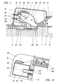
- the system essentially consists on the gas turbine side (1) of the rotor 11 bladed with rotor blades and the blade carrier 12 equipped with guide blades.
- the blade carrier 12 is correspondingly provided via projections Recordings suspended in the turbine housing 13.
- the exhaust housing 14 is flanged to the turbine housing 13.
- the turbine housing 13 also includes the collecting space 15 for the compressed combustion air. From this collecting space, part of the combustion air passes through a perforated cover 30 in the direction of the arrow directly into the annular combustion chamber 3, which in turn enters the turbine inlet, i.e. flows upstream of the first guide row.
- the compressed air arrives in the collecting space from the diffuser 22 of the compressor 2. Only the last four stages of the latter are shown.
- the blading of the compressor and the turbine sit on the common shaft 11, the central axis of which represents the longitudinal axis 10 of the gas turbine unit.
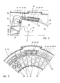
- the combustion chamber 3 is equipped at its head end with premix burners 20, as are known, for example, from EP-A1-387 532.
- a premix burner shown only schematically in FIG. 2, is a so-called double-cone burner. It essentially consists of two hollow, conical partial bodies 26, 27 which are nested one inside the other in the direction of flow. The respective central axes of the two partial bodies are offset from one another. The adjacent walls of the two partial bodies in their longitudinal extent form tangential slots 28 for the combustion air, which in this way reaches the interior of the burner.
- a fuel nozzle 29 for liquid fuel is arranged there. The fuel is injected into the hollow cone at an acute angle. The resulting conical liquid fuel profile is enclosed by the combustion air flowing in tangentially.
- the concentration of the fuel is continuously reduced in the axial direction due to the mixing with the combustion air.
- the burner can also be operated with gaseous fuel.
- gas inflow openings distributed in the longitudinal direction are provided in the region of the tangential slots in the walls of the two partial bodies.
- the mixture formation with the combustion air thus begins in the zone of the inlet slots 28.
- mixed operation with both types of fuel is also possible in this way.
- a fuel concentration that is as homogeneous as possible is established over the loaded cross-section.
- a defined dome-shaped return flow zone is created at the burner outlet, at the tip of which the ignition takes place.
- the combustion gases reach very high temperatures, which places special demands on the combustion chamber walls to be cooled.
- the annular combustion chamber extends downstream of the burner orifices up to the turbine inlet. It is limited both inside and outside by walls to be cooled, which are usually designed as self-supporting structures.
- the present combustion chamber is equipped with 72 of the said burners 20. 3, which shows a quarter-circle section, shows the arrangement thereof.
- Two burners are arranged radially one above the other on a front segment 31. 36 of these adjacent front segments form a closed circular ring, which in this way forms a heat shield.
- the two burners from adjacent front segments are each radially offset. This means that the radially outer burner of every second front segment directly adjoins the outer ring wall of the combustion chamber, as can also be seen in FIG. 3.
- the radially inner burners of the other front segments are therefore arranged in the immediate vicinity of the inner ring wall. This results in an uneven thermal load on the corresponding ring walls the scope.
- a rinsed Helmholtz resonator 21 is now housed for soundproofing the combustion chamber.
- a Helmholtz damper essentially consists of the actual resonance volume 50, an air inlet opening to the Helmholz volume, which is designed here as a feed pipe 51, and a damping pipe 52 opening into the interior of the combustion chamber. The purge air is drawn from the head space 49 by the damper.
- the feed tubes 51 are dimensioned such that they cause a relatively high pressure drop for the air flow.
- the damping tubes 52 allow the air to enter the interior of the combustion chamber with a low residual pressure drop.
- the limitation of the pressure drop in the damping tubes results from the requirement that even with an uneven pressure distribution on the inside of the combustion chamber wall, an adequate air flow into the combustion chamber is always guaranteed.
- hot gas must not enter the Helmholtz resonator in the opposite direction at any point.
- the choice of the size of the Helmholtz volume 50 results from the requirement that the phase angle between the fluctuations in the damping air mass flows through the supply and damping tubes should be greater than or equal to i T 12.
- this requirement means that the volume should be at least so large that the Helmholtz frequency of the resonator, which is formed by the volume 50 and the openings 51 and 52, is at least the frequency of the combustion chamber vibration to be damped.
- the volume of the Helmholtz resonator used is preferably designed for the lowest natural frequency of the combustion chamber. It is also possible to choose an even larger volume. It is thereby achieved that a pressure fluctuation on the inside of the combustion chamber leads to a strongly opposite-phase fluctuation in the air mass flow, because the fluctuations in the damping air mass flows through the supply pipes and the damping pipes are no longer in phase.
- the feed pipe 51 determines the pressure drop.
- the speed at the end of the feed pipe is adjusted so that the dynamic pressure of the jet together with the losses corresponds to the pressure drop across the combustion chamber.
- the average flow velocity in the damping tube in the present case of a gas turbine combustion chamber can typically be 2 to 4 m / s with an ideal design. So it is very small compared to the vibration amplitude, which means that the air particles move back and forth pulsating in the damping tube. Nevertheless, only enough air is allowed to flow through that a significant heating of the resonator is avoided. Heating by radiation from the area of the combustion chamber would result in the frequency not remaining stable. The flushing should therefore only dissipate the radiated heat.
- the location of the damping is decisive for the stabilization of a thermoacoustic oscillation.
- the greatest increase occurs when the reaction rate and the pressure disturbance oscillate in phase.
- the strongest reaction rate usually occurs near the center of the combustion zone. Therefore, the highest fluctuation in the reaction rate will also be there, if one occurs.
- the arrangement of the dampers at the radially outer or inner end of the front segments has a favorable effect, since in this way the respective damper is located in the middle of three burners.
- the housing of the Helmholtz damper is screwed into the respective front segment 31 from the head space 49 by means of a hollow threaded pin 55.
- the damping tube 52 protruding into the volume 50 is designed to be exchangeable. For this purpose, it penetrates the hollow threaded pin from the combustion chamber and is latched in the front segment by means of a bayonet lock 53.
- Spring means 54 ensure that the bayonet catch on the front segment is positively locked.
- the frequency spectrum is measured with Helmholtz dampers sealed with blind flanges.
- the required length and inner diameter of the damping tubes can be calculated for a given damping volume.
- the pipes determined in this way are then installed with the combustion chamber turned off. It goes without saying that several critical vibrations of different frequencies can also be damped in this way by installing different damper tubes.
- the generally cooled walls of the combustion chamber must be provided with a manhole.
- these walls are of a special kind in order not to impair the cooling.
- the thermally highly loaded interior of the combustion chamber is divided into two zones, the walls of which are cooled in different ways.
- a secondary zone 32 lying downstream and opening into the turbine inlet is delimited by a double-walled flame tube. It consists both on its inner ring 33 and on its outer ring 34 from a flangeless, welded sheet metal construction, which is held together by spacers, not shown. Both rings 33 and 34 are open at their turbine end and form the entry for the cooling air there.
- the annular space 35 between the double wall of the outer ring 34 draws the air directly from the collecting space 15, as can be seen in FIG. 1. With efficient convection cooling, the air flows in counterflow to the combustion chamber flow in the direction of the primary zone 36.
- the annular space 37 between the double wall of the inner ring 33 is supplied with air from a hub diffuser 38.
- This hub diffuser which connects to the compressor diffuser 22, is delimited on the one hand by a drum cover 24 and on the other hand by an annular shell 39.
- the latter is connected to the drum cover 24 via ribs (not shown).
- the air flows in the counterflow to the combustion chamber flow in the direction of the primary zone 36.
- the cooling of the highly stressed primary zone walls is now carried out by means of individually cooled cooling segments 40. These cooling segments lined up in the circumferential direction and in the axial direction form their flow-limiting wall over the entire axial extent of the primary zone 36. Single cooling has the advantage of a low pressure drop.
- the thermally highly stressed cooling segments 40 consist of a high-temperature, precision cast alloy. They are suspended in the circumferential direction with two feet 42 each provided with supporting teeth in corresponding grooves in a supporting structure, in a manner similar to how guide vane feet are fastened in blade carriers.
- this support structure hereinafter referred to as segment carrier 43, consists of two cast half-shells with a horizontal parting plane and not shown claws with which it is supported in the turbine housing.
- cooling segments 40 arranged side by side in the axial direction corresponds to the number of front segments 31, so that a cooling segment is assigned to each front segment and to the burner 20 closest to the wall (FIG. 3).
- a cooling segment is supplied with cooling air via a radially directed opening 46 which penetrates the segment carrier 43 and connects the collecting space 15 to one end of the cooling chamber 44 lying in the circumferential direction.
- the outlet opening 47 At the opposite end of this same cooling chamber is the outlet opening 47 in the segment carrier. Both the opening 46 and the outlet opening 47 can either be individual bores or elongated holes that extend in the axial direction over a large part of the segment width.
- the outlet opening 47 opens into a channel 48 which penetrates the segment carrier 43 in its entire axial extent and is open on both sides.
- a channel 48 which penetrates the segment carrier 43 in its entire axial extent and is open on both sides.
- this outer ring is flanged to the segment carrier, the contour of the inner wall being matched to the contour of the cooling segments.
- the channel 48 opens against a head space 49, which is delimited by the cover 30 and the front segments 31.
- the cover 30 is also flanged to the segment carrier 43.
- These axial channels 43 serve to jointly guide the segment cooling air and the cooling air acting on the secondary zone.
- a part 143 of the upper half of the segment carrier 43 which extends over a plurality of cooling segments and forms the above-mentioned manhole is designed to be removable together with the cooling segments 40 suspended therein.
- This detachable part 143 of the segment carrier comprises two cooling segments 40 in the circumferential direction and in the axial direction (shown hatched in FIGS. 2 and 3).
- the part 143 closing the manhole is screwed to the segment carrier 43 by means of a bracket 45 projecting on all sides. It goes without saying that a part of the turbine housing 13 which corresponds to the size of the manhole must also be opened and is therefore designed as an end cover 113.
Priority Applications (5)
| Application Number | Priority Date | Filing Date | Title |
|---|---|---|---|
| DE59208715T DE59208715D1 (de) | 1992-11-09 | 1992-11-09 | Gasturbinen-Brennkammer |
| EP92119124A EP0597138B1 (fr) | 1992-11-09 | 1992-11-09 | Chambre de combustion pour turbine à gaz |
| US08/132,185 US5373695A (en) | 1992-11-09 | 1993-10-06 | Gas turbine combustion chamber with scavenged Helmholtz resonators |
| KR1019930021695A KR940011862A (ko) | 1992-11-09 | 1993-10-19 | 가스 터빈 연소실 |
| JP27936693A JP3397858B2 (ja) | 1992-11-09 | 1993-11-09 | ガスタービンの燃焼室 |
Applications Claiming Priority (1)
| Application Number | Priority Date | Filing Date | Title |
|---|---|---|---|
| EP92119124A EP0597138B1 (fr) | 1992-11-09 | 1992-11-09 | Chambre de combustion pour turbine à gaz |
Publications (2)
| Publication Number | Publication Date |
|---|---|
| EP0597138A1 true EP0597138A1 (fr) | 1994-05-18 |
| EP0597138B1 EP0597138B1 (fr) | 1997-07-16 |
Family
ID=8210218
Family Applications (1)
| Application Number | Title | Priority Date | Filing Date |
|---|---|---|---|
| EP92119124A Expired - Lifetime EP0597138B1 (fr) | 1992-11-09 | 1992-11-09 | Chambre de combustion pour turbine à gaz |
Country Status (5)
| Country | Link |
|---|---|
| US (1) | US5373695A (fr) |
| EP (1) | EP0597138B1 (fr) |
| JP (1) | JP3397858B2 (fr) |
| KR (1) | KR940011862A (fr) |
| DE (1) | DE59208715D1 (fr) |
Cited By (19)
| Publication number | Priority date | Publication date | Assignee | Title |
|---|---|---|---|---|
| EP0892216A1 (fr) * | 1997-07-15 | 1999-01-20 | Abb Research Ltd. | Structure de paroi de chambre de combustion absorbant les vibrations |
| EP0892217A1 (fr) * | 1997-07-15 | 1999-01-20 | Abb Research Ltd. | Dispositif d'atténuation des vibrations d'une chambre de combustion |
| EP0976982A1 (fr) | 1998-07-27 | 2000-02-02 | Asea Brown Boveri AG | Procédé de fonctionnement d'une chambre de combustion de turbine à gaz à carburant liquide |
| EP1004823A3 (fr) * | 1998-11-10 | 2000-11-29 | Asea Brown Boveri AG | Dispositif d'amortissement pour la réduction de l'amplitude d'oscillation d'ondes acoustiques pour un brûleur |
| WO2003058123A1 (fr) | 2002-01-14 | 2003-07-17 | Alstom Technology Ltd | Ensemble de brûleurs pour chambre de combustion annulaire de turbine à gaz |
| WO2003060381A1 (fr) | 2002-01-16 | 2003-07-24 | Alstom Technology Ltd | Chambre de combustion et dispositif d'amortissement destine a reduire des pulsations de chambre de combustion dans un systeme de turbines a gaz |
| EP1342952A1 (fr) * | 2002-03-07 | 2003-09-10 | Siemens Aktiengesellschaft | Brûleur, procédé de fonctionnement d'un brûleur et turbine à gaz |
| EP1342953A1 (fr) | 2002-03-07 | 2003-09-10 | Siemens Aktiengesellschaft | Turbine à gaz |
| DE102006007711A1 (de) * | 2006-02-14 | 2007-08-16 | Deutsches Zentrum für Luft- und Raumfahrt e.V. | Brennkammer und Verfahren zur Einstellung der akustischen Eigenschaften einer Brennkammer |
| GB2443838A (en) * | 2006-11-16 | 2008-05-21 | Rolls Royce Plc | Combustion Control for a Gas Turbine |
| DE19640980B4 (de) * | 1996-10-04 | 2008-06-19 | Alstom | Vorrichtung zur Dämpfung von thermoakustischen Schwingungen in einer Brennkammer |
| US7661267B2 (en) | 2003-12-16 | 2010-02-16 | Ansaldo Energia S.P.A. | System for damping thermo-acoustic instability in a combustor device for a gas turbine |
| EP2187125A1 (fr) | 2008-09-24 | 2010-05-19 | Siemens Aktiengesellschaft | Dispositif et procédé destinés à l'amortissement d'oscillations de combustion |
| WO2010115980A2 (fr) | 2009-04-11 | 2010-10-14 | Alstom Technology Ltd. | Chambre de combustion dotée d'un amortisseur de helmholtz |
| US7878799B2 (en) | 2004-03-31 | 2011-02-01 | Alstom Technology Ltd | Multiple burner arrangement for operating a combustion chamber, and method for operating the multiple burner arrangement |
| EP2383515A1 (fr) | 2010-04-28 | 2011-11-02 | Siemens Aktiengesellschaft | Système de brûleur et procédé d'amortissement d'un tel système de brûleur |
| EP2383514A1 (fr) | 2010-04-28 | 2011-11-02 | Siemens Aktiengesellschaft | Système de brûleur et procédé d'amortissement d'un tel système de brûleur |
| US8206079B2 (en) | 2007-05-02 | 2012-06-26 | Rolls Royce Plc | Temperature controlling apparatus |
| WO2015176887A1 (fr) | 2014-05-19 | 2015-11-26 | Siemens Aktiengesellschaft | Ensemble formant brûleur à résonateur |
Families Citing this family (64)
| Publication number | Priority date | Publication date | Assignee | Title |
|---|---|---|---|---|
| DE4411624A1 (de) * | 1994-04-02 | 1995-10-05 | Abb Management Ag | Brennkammer mit Vormischbrennern |
| US5644918A (en) * | 1994-11-14 | 1997-07-08 | General Electric Company | Dynamics free low emissions gas turbine combustor |
| US5685157A (en) * | 1995-05-26 | 1997-11-11 | General Electric Company | Acoustic damper for a gas turbine engine combustor |
| DE19523094A1 (de) * | 1995-06-26 | 1997-01-02 | Abb Management Ag | Brennkammer |
| US6464489B1 (en) * | 1997-11-24 | 2002-10-15 | Alstom | Method and apparatus for controlling thermoacoustic vibrations in a combustion system |
| SE9802707L (sv) * | 1998-08-11 | 2000-02-12 | Abb Ab | Brännkammaranordning och förfarande för att reducera inverkan av akustiska trycksvängningar i en brännkammaranordning |
| EP0990851B1 (fr) | 1998-09-30 | 2003-07-23 | ALSTOM (Switzerland) Ltd | Chambre de combustion pour une turbine à gaz |
| US6351947B1 (en) | 2000-04-04 | 2002-03-05 | Abb Alstom Power (Schweiz) | Combustion chamber for a gas turbine |
| DE10026121A1 (de) | 2000-05-26 | 2001-11-29 | Alstom Power Nv | Vorrichtung zur Dämpfung akustischer Schwingungen in einer Brennkammer |
| US6530221B1 (en) | 2000-09-21 | 2003-03-11 | Siemens Westinghouse Power Corporation | Modular resonators for suppressing combustion instabilities in gas turbine power plants |
| DE10058688B4 (de) * | 2000-11-25 | 2011-08-11 | Alstom Technology Ltd. | Dämpferanordnung zur Reduktion von Brennkammerpulsationen |
| DE10108560A1 (de) | 2001-02-22 | 2002-09-05 | Alstom Switzerland Ltd | Verfahren zum Betrieb einer Ringbrennkammer sowie eine diesbezügliche Ringbrennkammer |
| JP3962554B2 (ja) * | 2001-04-19 | 2007-08-22 | 三菱重工業株式会社 | ガスタービン燃焼器及びガスタービン |
| EP1270902B1 (fr) | 2001-06-22 | 2009-10-21 | ALSTOM Technology Ltd | Procédé de démarrage d'un système de turbine à gaz |
| CA2399534C (fr) * | 2001-08-31 | 2007-01-02 | Mitsubishi Heavy Industries, Ltd. | Turbine a gaz et chambre de combustion connexe |
| KR100804951B1 (ko) * | 2001-11-27 | 2008-02-20 | 주식회사 포스코 | 가스터빈 연소기의 충격흡수장치 |
| EP1568869B1 (fr) * | 2002-12-02 | 2016-09-14 | Mitsubishi Hitachi Power Systems, Ltd. | Chambre de combustion de turbine a gaz et turbine a gaz equipee de cette chambre de combustion |
| GB2396687A (en) * | 2002-12-23 | 2004-06-30 | Rolls Royce Plc | Helmholtz resonator for combustion chamber use |
| GB0305025D0 (en) * | 2003-03-05 | 2003-04-09 | Alstom Switzerland Ltd | Method and device for efficient usage of cooling air for acoustic damping of combustion chamber pulsations |
| US7272931B2 (en) * | 2003-09-16 | 2007-09-25 | General Electric Company | Method and apparatus to decrease combustor acoustics |
| US7464552B2 (en) * | 2004-07-02 | 2008-12-16 | Siemens Energy, Inc. | Acoustically stiffened gas-turbine fuel nozzle |
| US7334408B2 (en) * | 2004-09-21 | 2008-02-26 | Siemens Aktiengesellschaft | Combustion chamber for a gas turbine with at least two resonator devices |
| CH698104B1 (de) | 2004-11-03 | 2009-05-29 | Alstom Technology Ltd | Brennstoffdrosselventil zum Betreiben einer Brenneranordnung einer Gasturbine sowie Brenneranordnung mit Brennstoffdrosselventil. |
| ATE366896T1 (de) * | 2005-02-04 | 2007-08-15 | Enel Produzione Spa | Dämpfung von thermoakustischen schwingungen in einer gasturbinenbrennkammer mit ringförmiger kammer |
| DE102005062284B4 (de) | 2005-12-24 | 2019-02-28 | Ansaldo Energia Ip Uk Limited | Brennkammer für eine Gasturbine |
| US7413053B2 (en) * | 2006-01-25 | 2008-08-19 | Siemens Power Generation, Inc. | Acoustic resonator with impingement cooling tubes |
| US7600370B2 (en) * | 2006-05-25 | 2009-10-13 | Siemens Energy, Inc. | Fluid flow distributor apparatus for gas turbine engine mid-frame section |
| GB0610800D0 (en) * | 2006-06-01 | 2006-07-12 | Rolls Royce Plc | Combustion chamber for a gas turbine engine |
| US7788926B2 (en) * | 2006-08-18 | 2010-09-07 | Siemens Energy, Inc. | Resonator device at junction of combustor and combustion chamber |
| DE102006053278A1 (de) * | 2006-11-03 | 2008-05-08 | Deutsches Zentrum für Luft- und Raumfahrt e.V. | Brennkammervorrichtung |
| FR2920525B1 (fr) * | 2007-08-31 | 2014-06-13 | Snecma | Separateur pour alimentation de l'air de refroidissement d'une turbine |
| US8516819B2 (en) | 2008-07-16 | 2013-08-27 | Siemens Energy, Inc. | Forward-section resonator for high frequency dynamic damping |
| US8408004B2 (en) * | 2009-06-16 | 2013-04-02 | General Electric Company | Resonator assembly for mitigating dynamics in gas turbines |
| US8336312B2 (en) * | 2009-06-17 | 2012-12-25 | Siemens Energy, Inc. | Attenuation of combustion dynamics using a Herschel-Quincke filter |
| US8789372B2 (en) * | 2009-07-08 | 2014-07-29 | General Electric Company | Injector with integrated resonator |
| ES2400267T3 (es) * | 2009-08-31 | 2013-04-08 | Alstom Technology Ltd | Dispositivo de combustión de una turbina de gas |
| RU2508506C2 (ru) * | 2009-09-01 | 2014-02-27 | Дженерал Электрик Компани | Способ и установка для ввода текучей среды в камеру сгорания газотурбинного двигателя |
| EP2299177A1 (fr) * | 2009-09-21 | 2011-03-23 | Alstom Technology Ltd | Chambre de combustion de turbine à gaz |
| JP5448762B2 (ja) * | 2009-12-02 | 2014-03-19 | 三菱重工業株式会社 | ガスタービン用燃焼バーナ |
| CH702594A1 (de) * | 2010-01-28 | 2011-07-29 | Alstom Technology Ltd | Helmholtzdämpfer für den Einbau in die Brennkammer einer Gasturbine sowie Verfahren zum Einbau eines solchen Helmholtzdämpfers. |
| FR2958016B1 (fr) * | 2010-03-23 | 2017-03-24 | Snecma | Methode de reduction des instabilites de combustion par le choix du positionnement d'un prelevement d'air sur une turbomachine |
| US9127837B2 (en) * | 2010-06-22 | 2015-09-08 | Carrier Corporation | Low pressure drop, low NOx, induced draft gas heaters |
| US9546558B2 (en) | 2010-07-08 | 2017-01-17 | Siemens Energy, Inc. | Damping resonator with impingement cooling |
| EP2474784A1 (fr) | 2011-01-07 | 2012-07-11 | Siemens Aktiengesellschaft | Système de combustion pour turbine à gaz comprenant un résonateur |
| FR2977639B1 (fr) * | 2011-07-07 | 2013-08-09 | Snecma | Element d'injection |
| US9341375B2 (en) | 2011-07-22 | 2016-05-17 | General Electric Company | System for damping oscillations in a turbine combustor |
| US8469141B2 (en) | 2011-08-10 | 2013-06-25 | General Electric Company | Acoustic damping device for use in gas turbine engine |
| US8966903B2 (en) * | 2011-08-17 | 2015-03-03 | General Electric Company | Combustor resonator with non-uniform resonator passages |
| EP2559945A1 (fr) * | 2011-08-17 | 2013-02-20 | Siemens Aktiengesellschaft | Agencement de combustion et turbine dotée d'amortissement |
| US9400108B2 (en) | 2013-05-14 | 2016-07-26 | Siemens Aktiengesellschaft | Acoustic damping system for a combustor of a gas turbine engine |
| EP2816288B1 (fr) * | 2013-05-24 | 2019-09-04 | Ansaldo Energia IP UK Limited | Chambre de combustion de turbine à gaz avec amortisseur de vibrations |
| US9890954B2 (en) | 2014-08-19 | 2018-02-13 | General Electric Company | Combustor cap assembly |
| US9964308B2 (en) | 2014-08-19 | 2018-05-08 | General Electric Company | Combustor cap assembly |
| US10267523B2 (en) * | 2014-09-15 | 2019-04-23 | Ansaldo Energia Ip Uk Limited | Combustor dome damper system |
| JP2018501458A (ja) * | 2014-12-01 | 2018-01-18 | シーメンス アクチエンゲゼルシヤフトSiemens Aktiengesellschaft | ガスタービンエンジン用の交換可能な調量管を備えた共鳴器 |
| EP3029377B1 (fr) * | 2014-12-03 | 2018-04-11 | Ansaldo Energia Switzerland AG | Amortisseur pour une turbine à gaz |
| US9835333B2 (en) * | 2014-12-23 | 2017-12-05 | General Electric Company | System and method for utilizing cooling air within a combustor |
| US10221769B2 (en) * | 2016-12-02 | 2019-03-05 | General Electric Company | System and apparatus for gas turbine combustor inner cap and extended resonating tubes |
| US10220474B2 (en) * | 2016-12-02 | 2019-03-05 | General Electricd Company | Method and apparatus for gas turbine combustor inner cap and high frequency acoustic dampers |
| JP7008722B2 (ja) * | 2017-03-30 | 2022-01-25 | シーメンス アクティエンゲゼルシャフト | ガスタービンエンジンの燃焼器セクションにおける冷却流体の二重利用のための導管配置を備えたシステム |
| US20180313540A1 (en) * | 2017-05-01 | 2018-11-01 | General Electric Company | Acoustic Damper for Gas Turbine Engine Combustors |
| JP2020056542A (ja) * | 2018-10-02 | 2020-04-09 | 川崎重工業株式会社 | 航空機用のアニュラ型ガスタービン燃焼器 |
| US11204204B2 (en) | 2019-03-08 | 2021-12-21 | Toyota Motor Engineering & Manufacturing North America, Inc. | Acoustic absorber with integrated heat sink |
| CN116293795A (zh) * | 2021-12-06 | 2023-06-23 | 通用电气阿维奥有限责任公司 | 用于燃气涡轮燃烧器应用的圆顶集成声学阻尼器 |
Citations (4)
| Publication number | Priority date | Publication date | Assignee | Title |
|---|---|---|---|---|
| US2881337A (en) * | 1957-07-01 | 1959-04-07 | Gen Electric | Acoustically treated motor |
| US4012902A (en) * | 1974-03-29 | 1977-03-22 | Phillips Petroleum Company | Method of operating a gas turbine combustor having an independent airstream to remove heat from the primary combustion zone |
| FR2570129A1 (fr) * | 1984-09-05 | 1986-03-14 | Messerschmitt Boelkow Blohm | Dispositif pour amortir les vibrations dans la chambre de combustion de moteurs-fusees a propergols liquides |
| EP0576717A1 (fr) * | 1992-07-03 | 1994-01-05 | Abb Research Ltd. | Chambre de combustion de turbine à gaz |
Family Cites Families (7)
| Publication number | Priority date | Publication date | Assignee | Title |
|---|---|---|---|---|
| US3850261A (en) * | 1973-03-01 | 1974-11-26 | Gen Electric | Wide band width single layer sound suppressing panel |
| US3978662A (en) * | 1975-04-28 | 1976-09-07 | General Electric Company | Cooling ring construction for combustion chambers |
| US4077205A (en) * | 1975-12-05 | 1978-03-07 | United Technologies Corporation | Louver construction for liner of gas turbine engine combustor |
| GB2036296B (en) * | 1978-11-20 | 1982-12-01 | Rolls Royce | Gas turbine |
| US5082421A (en) * | 1986-04-28 | 1992-01-21 | Rolls-Royce Plc | Active control of unsteady motion phenomena in turbomachinery |
| US4944362A (en) * | 1988-11-25 | 1990-07-31 | General Electric Company | Closed cavity noise suppressor |
| CH678757A5 (fr) * | 1989-03-15 | 1991-10-31 | Asea Brown Boveri |
-
1992
- 1992-11-09 EP EP92119124A patent/EP0597138B1/fr not_active Expired - Lifetime
- 1992-11-09 DE DE59208715T patent/DE59208715D1/de not_active Expired - Lifetime
-
1993
- 1993-10-06 US US08/132,185 patent/US5373695A/en not_active Expired - Lifetime
- 1993-10-19 KR KR1019930021695A patent/KR940011862A/ko not_active Application Discontinuation
- 1993-11-09 JP JP27936693A patent/JP3397858B2/ja not_active Expired - Fee Related
Patent Citations (4)
| Publication number | Priority date | Publication date | Assignee | Title |
|---|---|---|---|---|
| US2881337A (en) * | 1957-07-01 | 1959-04-07 | Gen Electric | Acoustically treated motor |
| US4012902A (en) * | 1974-03-29 | 1977-03-22 | Phillips Petroleum Company | Method of operating a gas turbine combustor having an independent airstream to remove heat from the primary combustion zone |
| FR2570129A1 (fr) * | 1984-09-05 | 1986-03-14 | Messerschmitt Boelkow Blohm | Dispositif pour amortir les vibrations dans la chambre de combustion de moteurs-fusees a propergols liquides |
| EP0576717A1 (fr) * | 1992-07-03 | 1994-01-05 | Abb Research Ltd. | Chambre de combustion de turbine à gaz |
Non-Patent Citations (3)
| Title |
|---|
| FR-A- 2 570 129 * |
| US-A- 2 881 337 * |
| US-A- 4 012 902 * |
Cited By (37)
| Publication number | Priority date | Publication date | Assignee | Title |
|---|---|---|---|---|
| DE19640980B4 (de) * | 1996-10-04 | 2008-06-19 | Alstom | Vorrichtung zur Dämpfung von thermoakustischen Schwingungen in einer Brennkammer |
| EP0892217A1 (fr) * | 1997-07-15 | 1999-01-20 | Abb Research Ltd. | Dispositif d'atténuation des vibrations d'une chambre de combustion |
| US6164058A (en) * | 1997-07-15 | 2000-12-26 | Abb Research Ltd. | Arrangement for damping combustion-chamber oscillations |
| EP0892216A1 (fr) * | 1997-07-15 | 1999-01-20 | Abb Research Ltd. | Structure de paroi de chambre de combustion absorbant les vibrations |
| EP0976982A1 (fr) | 1998-07-27 | 2000-02-02 | Asea Brown Boveri AG | Procédé de fonctionnement d'une chambre de combustion de turbine à gaz à carburant liquide |
| EP1004823A3 (fr) * | 1998-11-10 | 2000-11-29 | Asea Brown Boveri AG | Dispositif d'amortissement pour la réduction de l'amplitude d'oscillation d'ondes acoustiques pour un brûleur |
| US7055331B2 (en) | 2002-01-14 | 2006-06-06 | Alstom Technology Ltd | Burner arrangement for the annular combustion chamber of a gas turbine |
| WO2003058123A1 (fr) | 2002-01-14 | 2003-07-17 | Alstom Technology Ltd | Ensemble de brûleurs pour chambre de combustion annulaire de turbine à gaz |
| WO2003060381A1 (fr) | 2002-01-16 | 2003-07-24 | Alstom Technology Ltd | Chambre de combustion et dispositif d'amortissement destine a reduire des pulsations de chambre de combustion dans un systeme de turbines a gaz |
| US7331182B2 (en) | 2002-01-16 | 2008-02-19 | Alstom Technology Ltd | Combustion chamber for a gas turbine |
| WO2003074936A1 (fr) * | 2002-03-07 | 2003-09-12 | Siemens Aktiengesellschaft | Turbine a gaz |
| CN1320314C (zh) * | 2002-03-07 | 2007-06-06 | 西门子公司 | 燃气轮机 |
| US7246493B2 (en) | 2002-03-07 | 2007-07-24 | Siemens Aktiengesellschaft | Gas turbine |
| US7320222B2 (en) | 2002-03-07 | 2008-01-22 | Siemens Aktiengesellschaft | Burner, method for operating a burner and gas turbine |
| EP1342953A1 (fr) | 2002-03-07 | 2003-09-10 | Siemens Aktiengesellschaft | Turbine à gaz |
| EP1342952A1 (fr) * | 2002-03-07 | 2003-09-10 | Siemens Aktiengesellschaft | Brûleur, procédé de fonctionnement d'un brûleur et turbine à gaz |
| WO2003074937A1 (fr) * | 2002-03-07 | 2003-09-12 | Siemens Aktiengesellschaft | Bruleur, procede de fonctionnement d'un bruleur et turbine a gaz |
| US7661267B2 (en) | 2003-12-16 | 2010-02-16 | Ansaldo Energia S.P.A. | System for damping thermo-acoustic instability in a combustor device for a gas turbine |
| US7878799B2 (en) | 2004-03-31 | 2011-02-01 | Alstom Technology Ltd | Multiple burner arrangement for operating a combustion chamber, and method for operating the multiple burner arrangement |
| DE102006007711A1 (de) * | 2006-02-14 | 2007-08-16 | Deutsches Zentrum für Luft- und Raumfahrt e.V. | Brennkammer und Verfahren zur Einstellung der akustischen Eigenschaften einer Brennkammer |
| DE102006007711B4 (de) * | 2006-02-14 | 2008-07-24 | Deutsches Zentrum für Luft- und Raumfahrt e.V. | Brennkammer und Verfahren zur Einstellung der akustischen Eigenschaften einer Brennkammer |
| GB2443838A (en) * | 2006-11-16 | 2008-05-21 | Rolls Royce Plc | Combustion Control for a Gas Turbine |
| GB2443838B (en) * | 2006-11-16 | 2009-01-28 | Rolls Royce Plc | Combustion control for a gas turbine |
| US8206079B2 (en) | 2007-05-02 | 2012-06-26 | Rolls Royce Plc | Temperature controlling apparatus |
| EP2187125A1 (fr) | 2008-09-24 | 2010-05-19 | Siemens Aktiengesellschaft | Dispositif et procédé destinés à l'amortissement d'oscillations de combustion |
| WO2010115980A2 (fr) | 2009-04-11 | 2010-10-14 | Alstom Technology Ltd. | Chambre de combustion dotée d'un amortisseur de helmholtz |
| WO2010115980A3 (fr) * | 2009-04-11 | 2011-10-20 | Alstom Technology Ltd. | Chambre de combustion dotée d'un amortisseur de helmholtz |
| CH700799A1 (de) * | 2009-04-11 | 2010-10-15 | Alstom Technology Ltd | Brennkammer mit Helmholtzdämpfer für eine Gasturbine. |
| AU2010233724B2 (en) * | 2009-04-11 | 2015-06-18 | General Electric Technology Gmbh | Combustion chamber having a helmholtz damper |
| EP2383515A1 (fr) | 2010-04-28 | 2011-11-02 | Siemens Aktiengesellschaft | Système de brûleur et procédé d'amortissement d'un tel système de brûleur |
| EP2383514A1 (fr) | 2010-04-28 | 2011-11-02 | Siemens Aktiengesellschaft | Système de brûleur et procédé d'amortissement d'un tel système de brûleur |
| WO2011134706A1 (fr) | 2010-04-28 | 2011-11-03 | Siemens Aktiengesellschaft | Système de combustion et procédé pour amortir les vibrations d'un tel système de combustion |
| WO2011134713A1 (fr) | 2010-04-28 | 2011-11-03 | Siemens Aktiengesellschaft | Système de combustion pour amortir un système de combustion |
| JP2013525737A (ja) * | 2010-04-28 | 2013-06-20 | シーメンス アクチエンゲゼルシヤフト | バーナ装置及びこの種のバーナの振動減衰方法 |
| US8631654B2 (en) | 2010-04-28 | 2014-01-21 | Siemens Aktiengesellschaft | Burner system and method for damping such a burner system |
| WO2015176887A1 (fr) | 2014-05-19 | 2015-11-26 | Siemens Aktiengesellschaft | Ensemble formant brûleur à résonateur |
| US10605457B2 (en) | 2014-05-19 | 2020-03-31 | Siemens Aktiengesellschaft | Burner arrangement with resonator |
Also Published As
| Publication number | Publication date |
|---|---|
| JP3397858B2 (ja) | 2003-04-21 |
| KR940011862A (ko) | 1994-06-22 |
| EP0597138B1 (fr) | 1997-07-16 |
| US5373695A (en) | 1994-12-20 |
| JPH06221563A (ja) | 1994-08-09 |
| DE59208715D1 (de) | 1997-08-21 |
Similar Documents
| Publication | Publication Date | Title |
|---|---|---|
| EP0597138B1 (fr) | Chambre de combustion pour turbine à gaz | |
| EP0781967B1 (fr) | Chambre de combustion annulaire pour turbine à gaz | |
| DE4316475C2 (de) | Gasturbinen-Brennkammer | |
| DE60007946T2 (de) | Eine Brennkammer | |
| EP0985882B1 (fr) | Amortissement des vibrations dans des combusteurs | |
| DE19640980B4 (de) | Vorrichtung zur Dämpfung von thermoakustischen Schwingungen in einer Brennkammer | |
| DE60224141T2 (de) | Gasturbine und Brennkammer dafür | |
| EP1534997B1 (fr) | Brûleur d'une turbine à gaz | |
| EP0592717B1 (fr) | Brûleur opérant au gaz du type à prémélange | |
| DE102008037480A1 (de) | Mager vorgemischte Dual-Fuel-Ringrohrbrennkammer mit Radial-Mehrring-Stufendüse | |
| EP0931979A1 (fr) | Procédé et dispositif pour supprimer les fluctuations par flamme et par pression dans un four | |
| EP0687860A2 (fr) | Chambre de combustion à allumage automatique | |
| DE102008002931A1 (de) | Vorrichtung/Verfahren zur Kühlung einer Brennkammer/Venturi-Düse in einem Brenner mit niedrigen NOx-Emissionen | |
| DE102014102782A1 (de) | Multiinjektor-Mikromischsystem | |
| CH702825B1 (de) | Turbinenbrennkammer-Einsatzanordnung. | |
| DE102008022669A1 (de) | Brennstoffdüse und Verfahren für deren Herstellung | |
| DE3222347A1 (de) | Schwingbrenner mit vormischung | |
| DE102011051366A1 (de) | Vorrichtung und Verfahren zum Mischen von Brennstoff in einer Gasturbinendüse | |
| DE10050248A1 (de) | Brenner | |
| WO2003074937A1 (fr) | Bruleur, procede de fonctionnement d'un bruleur et turbine a gaz | |
| EP1279898A2 (fr) | Brûleur à prémélange offrant une haute stabilité de flamme | |
| EP2006606A1 (fr) | Stabilisation sans tourbillonner de la flamme d'un brûleur à prémélange | |
| EP0995066B1 (fr) | Agencement de bruleurs pour une installation de chauffe, notamment une chambre de combustion de turbine a gaz | |
| EP2182285A1 (fr) | Pièce du brûleur pour une chambre de combustion d'une turbine à gaz et turbine à gaz | |
| DE102011000589A1 (de) | Axial gestufte Vormischbrennkammer |
Legal Events
| Date | Code | Title | Description |
|---|---|---|---|
| PUAI | Public reference made under article 153(3) epc to a published international application that has entered the european phase |
Free format text: ORIGINAL CODE: 0009012 |
|
| AK | Designated contracting states |
Kind code of ref document: A1 Designated state(s): CH DE FR GB LI NL |
|
| RBV | Designated contracting states (corrected) |
Designated state(s): CH DE FR GB LI NL |
|
| 17P | Request for examination filed |
Effective date: 19941031 |
|
| 17Q | First examination report despatched |
Effective date: 19951218 |
|
| GRAG | Despatch of communication of intention to grant |
Free format text: ORIGINAL CODE: EPIDOS AGRA |
|
| GRAH | Despatch of communication of intention to grant a patent |
Free format text: ORIGINAL CODE: EPIDOS IGRA |
|
| GRAH | Despatch of communication of intention to grant a patent |
Free format text: ORIGINAL CODE: EPIDOS IGRA |
|
| GRAA | (expected) grant |
Free format text: ORIGINAL CODE: 0009210 |
|
| AK | Designated contracting states |
Kind code of ref document: B1 Designated state(s): CH DE FR GB LI NL |
|
| PG25 | Lapsed in a contracting state [announced via postgrant information from national office to epo] |
Ref country code: NL Free format text: LAPSE BECAUSE OF FAILURE TO SUBMIT A TRANSLATION OF THE DESCRIPTION OR TO PAY THE FEE WITHIN THE PRESCRIBED TIME-LIMIT Effective date: 19970716 |
|
| RAP1 | Party data changed (applicant data changed or rights of an application transferred) |
Owner name: ASEA BROWN BOVERI AG |
|
| REG | Reference to a national code |
Ref country code: CH Ref legal event code: EP |
|
| REF | Corresponds to: |
Ref document number: 59208715 Country of ref document: DE Date of ref document: 19970821 |
|
| GBT | Gb: translation of ep patent filed (gb section 77(6)(a)/1977) |
Effective date: 19970919 |
|
| ET | Fr: translation filed | ||
| PG25 | Lapsed in a contracting state [announced via postgrant information from national office to epo] |
Ref country code: CH Free format text: LAPSE BECAUSE OF NON-PAYMENT OF DUE FEES Effective date: 19971130 Ref country code: LI Free format text: LAPSE BECAUSE OF NON-PAYMENT OF DUE FEES Effective date: 19971130 |
|
| NLV1 | Nl: lapsed or annulled due to failure to fulfill the requirements of art. 29p and 29m of the patents act | ||
| PLBE | No opposition filed within time limit |
Free format text: ORIGINAL CODE: 0009261 |
|
| STAA | Information on the status of an ep patent application or granted ep patent |
Free format text: STATUS: NO OPPOSITION FILED WITHIN TIME LIMIT |
|
| 26N | No opposition filed | ||
| REG | Reference to a national code |
Ref country code: CH Ref legal event code: PL |
|
| REG | Reference to a national code |
Ref country code: GB Ref legal event code: IF02 |
|
| REG | Reference to a national code |
Ref country code: GB Ref legal event code: 732E |
|
| REG | Reference to a national code |
Ref country code: FR Ref legal event code: CA Ref country code: FR Ref legal event code: CD |
|
| REG | Reference to a national code |
Ref country code: FR Ref legal event code: TP |
|
| PGFP | Annual fee paid to national office [announced via postgrant information from national office to epo] |
Ref country code: DE Payment date: 20091130 Year of fee payment: 18 |
|
| PGFP | Annual fee paid to national office [announced via postgrant information from national office to epo] |
Ref country code: FR Payment date: 20101109 Year of fee payment: 19 |
|
| PG25 | Lapsed in a contracting state [announced via postgrant information from national office to epo] |
Ref country code: DE Free format text: LAPSE BECAUSE OF THE APPLICANT RENOUNCES Effective date: 20101025 |
|
| PGFP | Annual fee paid to national office [announced via postgrant information from national office to epo] |
Ref country code: GB Payment date: 20101022 Year of fee payment: 19 |
|
| GBPC | Gb: european patent ceased through non-payment of renewal fee |
Effective date: 20111109 |
|
| REG | Reference to a national code |
Ref country code: FR Ref legal event code: ST Effective date: 20120731 |
|
| PG25 | Lapsed in a contracting state [announced via postgrant information from national office to epo] |
Ref country code: GB Free format text: LAPSE BECAUSE OF NON-PAYMENT OF DUE FEES Effective date: 20111109 |
|
| PG25 | Lapsed in a contracting state [announced via postgrant information from national office to epo] |
Ref country code: FR Free format text: LAPSE BECAUSE OF NON-PAYMENT OF DUE FEES Effective date: 20111130 |