EP0596713B1 - Keilrillenriemen - Google Patents
Keilrillenriemen Download PDFInfo
- Publication number
- EP0596713B1 EP0596713B1 EP93308774A EP93308774A EP0596713B1 EP 0596713 B1 EP0596713 B1 EP 0596713B1 EP 93308774 A EP93308774 A EP 93308774A EP 93308774 A EP93308774 A EP 93308774A EP 0596713 B1 EP0596713 B1 EP 0596713B1
- Authority
- EP
- European Patent Office
- Prior art keywords
- fibers
- belt
- layer
- power transmission
- outside
- Prior art date
- Legal status (The legal status is an assumption and is not a legal conclusion. Google has not performed a legal analysis and makes no representation as to the accuracy of the status listed.)
- Expired - Lifetime
Links
Images

Classifications
-
- F—MECHANICAL ENGINEERING; LIGHTING; HEATING; WEAPONS; BLASTING
- F16—ENGINEERING ELEMENTS AND UNITS; GENERAL MEASURES FOR PRODUCING AND MAINTAINING EFFECTIVE FUNCTIONING OF MACHINES OR INSTALLATIONS; THERMAL INSULATION IN GENERAL
- F16G—BELTS, CABLES, OR ROPES, PREDOMINANTLY USED FOR DRIVING PURPOSES; CHAINS; FITTINGS PREDOMINANTLY USED THEREFOR
- F16G5/00—V-belts, i.e. belts of tapered cross-section
- F16G5/20—V-belts, i.e. belts of tapered cross-section with a contact surface of special shape, e.g. toothed
-
- F—MECHANICAL ENGINEERING; LIGHTING; HEATING; WEAPONS; BLASTING
- F16—ENGINEERING ELEMENTS AND UNITS; GENERAL MEASURES FOR PRODUCING AND MAINTAINING EFFECTIVE FUNCTIONING OF MACHINES OR INSTALLATIONS; THERMAL INSULATION IN GENERAL
- F16G—BELTS, CABLES, OR ROPES, PREDOMINANTLY USED FOR DRIVING PURPOSES; CHAINS; FITTINGS PREDOMINANTLY USED THEREFOR
- F16G1/00—Driving-belts
- F16G1/28—Driving-belts with a contact surface of special shape, e.g. toothed
Definitions
- V-ribbed power transmission belts have a wide range of uses. They are commonly used in the automotive industry, on agricultural equipment, home appliances, etc.
- the fibers extend in a lateral direction, they dislodge readily from the inside belt surface during manufacture. Grinding of the inside surface of the belt tends to draw off any exposed fibers so that no significant amount of the laterally extending fibers remains exposed on the inside surface of the completed belt. As a result, a cooperating flat pulley will engage principally the rubber within which the fibers are embedded so that the frictional forces between the belt and pulley are significantly larger than they would be if the fiber was exposed. As a result, significant "creak noise”/"stick slip noise” is generated as slippage occurs between the belt and pulley.
- the present invention is directed to, among other things, overcoming the problem of stick slip noise during power transmission belt operation.
- the invention is particularly adaptable to avoid generation of stick slip noise between a V-ribbed belt and a cooperating flat pulley.
- the invention also affords advantages with the V-ribbed belt cooperating with a pulley having a complementary groove configuration.
- fibers in the first plurality of fibers are exposed at the inside surface of the belt over between 50-95% of the area of the inside surface of the belt.
- a power transmission belt having a body with an inside surface and an outside surface, with one of the inside and outside surfaces being configured to engage a pulley.
- a rubber layer defines one of the inside and outside body surfaces, with there being a plurality of fibers embedded in the rubber layer and exposed at the one of the inside and outside surfaces of the belt body.
- the belt has a length and the plurality of fibers is aligned with the length of the belt.
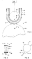
- the drive pulley 74 has a diameter of 14 to 16 mm and is driven at 1800 rpm.
- the driven pulley 76 has a diameter of 500 to 600 mm and a width W of 300 mm.
- the tensioning pulley 78 has a diameter of 30 mm.
- the belt 10, 10' used with this system 72 has a width of 4 mm.
- the belt 10, 10' is engaged by pulleys on both sides thereof and can be positively driven through a small diameter drive pulley 74 so that rotation is imparted to the larger flat pulley 76.
- the layer 26, 26' With the belt 10, 10' driving/being driven by a flat pulley, such as the pulley 76 in Figs. 5 and 6, it has been found that it is important to make the layer 26, 26' to have a thickness H equal to at least 10% of the height of the ribs 24, 24'.
- the layer 26, 26' is abraded significantly by the cooperating surface 84 on the pulley 76. Once the layer 26, 26' wears significantly, the sound limiting benefits of the invention diminish significantly.
Landscapes
- Engineering & Computer Science (AREA)
- General Engineering & Computer Science (AREA)
- Mechanical Engineering (AREA)
- Devices For Conveying Motion By Means Of Endless Flexible Members (AREA)
Claims (14)
- Kraftübertragungsriemen (10) miteinem sich erstreckenden Körper (12) mit einem Kompressionsbereich (22);einer ersten Anzahl (30) Kurzfasern, die in dem Kompressionsbereich (22) des Körpers (12) eingebettet und, bezüglich des Körpers (12), im wesentlichen in Längsrichtung ausgerichtet sind; undeiner zweiten Anzahl (32) Kurzfasern, die in dem Kompressionsbereich (22) des Körpers (12) eingebettet und, bezüglich des Körpers (12), transversal ausgerichtet sind, wobei der Riemen (10) innenseitige (34) und außenseitige (18, 20) Oberflächen aufweist, dadurch gekennzeichnet, daß die Fasern in der ersten Anzahl (30) Fasern freiliegende Fasern umfassen, die an der innenseitigen Oberfläche (34) des Riemens (10) freiliegen, und Fasern in der ersten Anzahl (30) von Fasern überstehende Fasern (30') umfassen, welche von der inneren Oberfläche (34) des Riemens vorragen.
- Kraftübertragungsriemen gemäß Anspruch 1, wobei die überstehenden Fasern 0,1 bis 3,0 mm von der innenseitigen Oberfläche (34) des Riemens vorragen.
- Kraftübertragungsriemen gemäß Anspruch 1 oder 2, wobei die erste Anzahl (30) Kurzfasern in einer ersten Schicht (26) in dem Kompressionsbereich (22) und die zweite Anzahl (32) Kurzfasern in einer zweiten Schicht (28) in dem Kompressionsbereich (22) eingebettet sind.
- Kraftübertragungsriemen gemäß Anspruch 3, wobei die erste Schicht (26) eine Abmessung zwischen der Innenseite (34) und der Außenseite (18, 20) des Riemens (10) aufweist, die geringer ist als die Abmessung der zweiten Schicht (28) zwischen der Innenseite (34) und Außenseite (18, 20) des Riemens (10).
- Kraftübertragungsriemen gemäß Anspruch 3 oder 4, wobei die erste (26) und zweite (28) Schicht aneinanderstoßen.
- Kraftübertragungsriemen nach einem der Ansprüche 3 bis 5, wobei eine sich in Längsrichtung erstreckende Rippe (24) durch den Körper (12) definiert wird, die Rippe (24) eine Höhe zwischen den innenseitigen (34) und außenseitigen (18, 20) Oberflächen des Riemens (10) aufweist, und die Abmessung der ersten Schicht (26) zwischen der Innenseite (34) und Außenseite (18, 20) des Riemens (10) 10 bis 30 % der Höhe der Rippe (24) beträgt.
- Kraftübertragungsriemen nach einem der vorhergehenden Ansprüche, wobei der Riemen (10) ein Keilrippenriemen ist.
- Kraftübertragungsriemen nach einem der vorhergehenden Ansprüche, wobei die erste Anzahl (30) Kurzfasern derart ausgerichtet ist, daß sie einen Winkel von nicht mehr als 30° mit der Längsrichtung des Riemenkörpers (12) bildet.
- Kraftübertragungsriemen nach einem der vorhergehenden Ansprüche, wobei die Fasern in der ersten Anzahl (30) Fasern eine Länge von 3 bis 10 mm aufweisen.
- Kraftübertragungsriemen nach einem der vorhergehenden Ansprüche, wobei die erste Anzahl (30) Fasern in einer Gummischicht (26) eingebettet ist, und die erste Anzahl (30) Fasern in einer Menge von 5 bis 30 Gewichtsteilen pro 100 Gewichtsteile Gummi in der Schicht (26) vorliegt.
- Kraftübertragungsriemen nach einem der vorhergehenden Ansprüche, wobei die Fasern in der ersten Anzahl (30) Fasern aus zumindest einem der Materialien a) Nylon, b) Vinylon, c) Polyester, d) aromatisches Polyamid, e) mit Nylon, Vinylon, Polyester und/oder aromatischem Polyamid gemischte Baumwollfäden und/oder f) mit Nylon, Vinylon, Polyester und/oder aromatischem Polyamid gemischte Stoffäden hergestellt sind.
- Kraftübertragungsriemen nach einem der vorhergehenden Ansprüche, wobei die freiliegenden Fasern in einem Bereich von 50 bis 95 % der innenseitigen Oberfläche (34) des Riemens freiliegen.
- Kraftübertragungsriemen nach einem der vorhergehenden Ansprüche, wobei der Riemen ein Doppelrippenriemen (36) mit innenseitigen und außenseitigen Oberflächen ist und eine neutrale Achse und sich in Längsrichtung erstreckende Rippen (40, 42) sowohl auf der Innenseite als auch der Außenseite der neutralen Achse aufweist, wobei sich die erste (46) und zweite Anzahl (50) Kurzfasern auf der Innenseite der neutralen Achse befinden, wobei eine dritte Anzahl (54) Kurzfasern in einer dritten Schicht (52) außerhalb der neutralen Achse und eine vierte Anzahl (58) Kurzfasern in einer vierten Schicht (56) außerhalb der neutralen Achse eingebettet sind, wobei die dritte Anzahl (54) Fasern im wesentlichen in Längsrichtung, bezüglich des Riemens (36), ausgerichtet ist, und wobei die vierte Anzahl (58) Fasern transversal, bezüglich des Riemens (36), ausgerichtet ist.
- Kraftübertragungsriemen nach Anspruch 13, wobei sich die dritte Schicht (52) außerhalb der vierten Schicht (56) befindet und an der Außenseite des Riemens (36) freiliegt, wobei Fasern der dritten Anzahl (54) Fasern auf der Außenseite des Riemens (36) freiliegen.
Applications Claiming Priority (2)
| Application Number | Priority Date | Filing Date | Title |
|---|---|---|---|
| JP82725/92 | 1992-11-04 | ||
| JP1992082725U JP2558070Y2 (ja) | 1992-11-04 | 1992-11-04 | Vリブドベルト |
Publications (2)
| Publication Number | Publication Date |
|---|---|
| EP0596713A1 EP0596713A1 (de) | 1994-05-11 |
| EP0596713B1 true EP0596713B1 (de) | 1997-05-21 |
Family
ID=13782398
Family Applications (1)
| Application Number | Title | Priority Date | Filing Date |
|---|---|---|---|
| EP93308774A Expired - Lifetime EP0596713B1 (de) | 1992-11-04 | 1993-11-03 | Keilrillenriemen |
Country Status (5)
| Country | Link |
|---|---|
| US (1) | US5415594A (de) |
| EP (1) | EP0596713B1 (de) |
| JP (1) | JP2558070Y2 (de) |
| CA (1) | CA2102246C (de) |
| DE (1) | DE69310868T2 (de) |
Families Citing this family (26)
| Publication number | Priority date | Publication date | Assignee | Title |
|---|---|---|---|---|
| US5498213A (en) * | 1994-12-15 | 1996-03-12 | Mitsuboshi Belting Ltd. | Power transmission belt |
| EP0694710B1 (de) * | 1994-07-27 | 1998-10-14 | Mitsuboshi Belting Ltd. | Doppelzeilrippenriemen |
| US5704862A (en) * | 1997-01-13 | 1998-01-06 | The Goodyear Tire & Rubber Company | Dual sided poly-V drive belt and pulley therefor |
| US6361462B1 (en) * | 1997-10-31 | 2002-03-26 | Mitsuboshi Belting Ltd. | V-ribbed power transmission belt |
| CA2313421A1 (en) | 1999-08-26 | 2001-02-26 | The Goodyear Tire & Rubber Company | Power transmission belt |
| US6464607B1 (en) * | 1999-12-15 | 2002-10-15 | The Goodyear Tire & Rubber Company | Power transmission belt |
| US6672983B2 (en) | 2000-12-21 | 2004-01-06 | The Goodyear Tire & Rubber Company | Power transmission drive system |
| US6802117B2 (en) * | 2001-02-05 | 2004-10-12 | George Dalisay | Device for circuit board insertion and extraction |
| DE10240988B4 (de) * | 2002-09-05 | 2014-02-27 | Inventio Ag | Aufzugsanlage mit einer aus Riemen und Scheiben bestehenden Antriebsübertragungsanordnung |
| EP1449474A1 (de) * | 2003-02-22 | 2004-08-25 | Vorwerk & Co. Interholding GmbH | In einer Teppichkehrmaschine angeordnete Bürstenwalze sowie Kupplung eines Antriebsteils mit einem Abtriebsteil |
| JP2005069358A (ja) | 2003-08-25 | 2005-03-17 | Bando Chem Ind Ltd | 摩擦伝動ベルト及びその製造方法 |
| DE102006007509B4 (de) * | 2006-02-16 | 2009-01-22 | Contitech Antriebssysteme Gmbh | Keilrippenriemen mit verbessertem Geräuschverhalten |
| US9506527B2 (en) * | 2006-04-07 | 2016-11-29 | Gates Corporation | Power transmission belt |
| US8357065B2 (en) * | 2006-06-01 | 2013-01-22 | The Gates Corporation | Power transmission belt and a process for its manufacture |
| US20080135343A1 (en) * | 2006-08-11 | 2008-06-12 | Ernst Ach | Elevator support means for an elevator system, elevator system with such an elevator support means and method for assembling such an elevator system |
| EP1886957A1 (de) | 2006-08-11 | 2008-02-13 | Inventio Ag | Aufzugriemen für eine Aufzuganlage und Verfahren zur Herstellung eines solchen Aufzugriemens |
| JP2008044791A (ja) * | 2006-08-11 | 2008-02-28 | Inventio Ag | エレベータシステムのエレベータ支持手段、そのようなエレベータ支持手段を備えるエレベータシステム、およびそのようなエレベータシステムの組み立て方法 |
| WO2008110241A2 (de) * | 2007-03-12 | 2008-09-18 | Inventio Ag | Aufzugsanlage, tragmittel für eine aufzugsanlage und verfahren zur herstellung eines tragmittels |
| CA2707489C (en) * | 2007-12-05 | 2014-04-29 | The Gates Corporation | Power transmission belt |
| JP4989556B2 (ja) * | 2008-05-26 | 2012-08-01 | 三ツ星ベルト株式会社 | Vリブドベルト |
| DE102009012395A1 (de) * | 2009-03-10 | 2010-09-16 | Siegfried Reichenbach | Zahnriemen |
| US20130190120A1 (en) * | 2009-04-30 | 2013-07-25 | The Gates Corporation | Double cogged v-belt for variable speed drive |
| US8206251B2 (en) * | 2009-04-30 | 2012-06-26 | The Gates Corporation | Double cogged V-belt for variable speed drive |
| JP5863712B2 (ja) * | 2013-02-21 | 2016-02-17 | バンドー化学株式会社 | 自動車の補機駆動ベルト伝動装置及びそれに用いるvリブドベルト |
| US9157503B2 (en) * | 2013-03-14 | 2015-10-13 | Dayco Ip Holdings, Llc | V-ribbed belt with spaced rib flank reinforcement |
| DE102017215654A1 (de) * | 2017-09-06 | 2019-03-07 | Contitech Antriebssysteme Gmbh | Antriebsriemen mit einer profilierten Riemenrückseite |
Family Cites Families (13)
| Publication number | Priority date | Publication date | Assignee | Title |
|---|---|---|---|---|
| US249404A (en) * | 1881-11-08 | Rufus e | ||
| IT1176829B (it) * | 1984-09-27 | 1987-08-18 | Pirelli | Cinghia trapezoidale |
| DK8604319A (de) * | 1985-09-13 | 1987-03-14 | ||
| DE3535676A1 (de) * | 1985-10-05 | 1987-05-07 | Continental Gummi Werke Ag | Treibriemen, insbesondere rillenriemen |
| IT1186158B (it) * | 1985-12-20 | 1987-11-18 | Pirelli Transmissioni Ind Spa | Cinghia trapezoidale,in particolare per variatori continui di velocita' |
| IT1188682B (it) * | 1986-05-21 | 1988-01-20 | Pirelli | Cinghia flessibile e relativa trasmissione |
| JPS62199553U (de) * | 1986-06-09 | 1987-12-18 | ||
| JPS63157552U (de) * | 1987-03-31 | 1988-10-17 | ||
| US4798566A (en) * | 1987-11-19 | 1989-01-17 | The Gates Rubber Company | Power transmission belt |
| US4904232A (en) * | 1988-10-31 | 1990-02-27 | Mitsuboshi Belting, Ltd. | Power transmission belt |
| US5197928A (en) * | 1989-11-20 | 1993-03-30 | Mitsuboshi Belting Ltd. | V-ribbed belt having protruding fibers |
| JPH0786377B2 (ja) * | 1990-01-31 | 1995-09-20 | 三ツ星ベルト株式会社 | Vベルト |
| JP3127849U (ja) * | 2006-10-03 | 2006-12-14 | 進 須藤 | 食品包装体 |
-
1992
- 1992-11-04 JP JP1992082725U patent/JP2558070Y2/ja not_active Expired - Fee Related
-
1993
- 1993-11-02 CA CA002102246A patent/CA2102246C/en not_active Expired - Fee Related
- 1993-11-03 EP EP93308774A patent/EP0596713B1/de not_active Expired - Lifetime
- 1993-11-03 US US08/147,117 patent/US5415594A/en not_active Expired - Lifetime
- 1993-11-03 DE DE69310868T patent/DE69310868T2/de not_active Expired - Lifetime
Also Published As
| Publication number | Publication date |
|---|---|
| EP0596713A1 (de) | 1994-05-11 |
| DE69310868T2 (de) | 1998-01-08 |
| DE69310868D1 (de) | 1997-06-26 |
| JP2558070Y2 (ja) | 1997-12-17 |
| JPH0640497U (ja) | 1994-05-31 |
| CA2102246C (en) | 1997-06-24 |
| US5415594A (en) | 1995-05-16 |
| CA2102246A1 (en) | 1994-05-05 |
Similar Documents
| Publication | Publication Date | Title |
|---|---|---|
| EP0596713B1 (de) | Keilrillenriemen | |
| EP0633408B1 (de) | Keilrippenriemen | |
| US5197928A (en) | V-ribbed belt having protruding fibers | |
| US5624338A (en) | Double V-ribbed belt | |
| US5120281A (en) | Power transmission belt | |
| JPH07117124B2 (ja) | 動力伝動用ベルト | |
| US4265627A (en) | Power transmission belt | |
| EP0514002B1 (de) | Keilrippenriemen | |
| US4504258A (en) | Power transmission belt | |
| EP0429299A2 (de) | Keilrippenriemen und Herstellungsverfahren | |
| AU2002237915B2 (en) | Endless power transmission belt | |
| AU2002237915A1 (en) | Endless power transmission belt | |
| CN220118572U (zh) | 一种传动带 | |
| US20060105874A1 (en) | Timing belt | |
| US5611745A (en) | Toothed power transmission belt | |
| US6626784B1 (en) | Low modulus belt | |
| US5427637A (en) | V-ribbed belt and method of fabricating the same | |
| US5358453A (en) | Cogged v-belt | |
| JP2848516B2 (ja) | Vリブドベルト | |
| JPH0110514Y2 (de) | ||
| JP2740753B2 (ja) | 歯付ベルト及びその製造方法 | |
| JPS596278Y2 (ja) | Vベルト | |
| EP0119335A1 (de) | Kraftübertragungsriemen | |
| CA1213451A (en) | V-belt for power transmission | |
| JPH0714681Y2 (ja) | 動力伝動用vベルト |
Legal Events
| Date | Code | Title | Description |
|---|---|---|---|
| PUAI | Public reference made under article 153(3) epc to a published international application that has entered the european phase |
Free format text: ORIGINAL CODE: 0009012 |
|
| AK | Designated contracting states |
Kind code of ref document: A1 Designated state(s): DE FR GB |
|
| 17P | Request for examination filed |
Effective date: 19940726 |
|
| 17Q | First examination report despatched |
Effective date: 19950706 |
|
| GRAG | Despatch of communication of intention to grant |
Free format text: ORIGINAL CODE: EPIDOS AGRA |
|
| GRAH | Despatch of communication of intention to grant a patent |
Free format text: ORIGINAL CODE: EPIDOS IGRA |
|
| GRAH | Despatch of communication of intention to grant a patent |
Free format text: ORIGINAL CODE: EPIDOS IGRA |
|
| GRAA | (expected) grant |
Free format text: ORIGINAL CODE: 0009210 |
|
| AK | Designated contracting states |
Kind code of ref document: B1 Designated state(s): DE FR GB |
|
| REF | Corresponds to: |
Ref document number: 69310868 Country of ref document: DE Date of ref document: 19970626 |
|
| ET | Fr: translation filed | ||
| PLBE | No opposition filed within time limit |
Free format text: ORIGINAL CODE: 0009261 |
|
| 26N | No opposition filed | ||
| REG | Reference to a national code |
Ref country code: GB Ref legal event code: IF02 |
|
| PGFP | Annual fee paid to national office [announced via postgrant information from national office to epo] |
Ref country code: DE Payment date: 20101126 Year of fee payment: 18 |
|
| PGFP | Annual fee paid to national office [announced via postgrant information from national office to epo] |
Ref country code: GB Payment date: 20101124 Year of fee payment: 18 |
|
| PGFP | Annual fee paid to national office [announced via postgrant information from national office to epo] |
Ref country code: FR Payment date: 20111128 Year of fee payment: 19 |
|
| GBPC | Gb: european patent ceased through non-payment of renewal fee |
Effective date: 20121103 |
|
| REG | Reference to a national code |
Ref country code: FR Ref legal event code: ST Effective date: 20130731 |
|
| REG | Reference to a national code |
Ref country code: DE Ref legal event code: R119 Ref document number: 69310868 Country of ref document: DE Effective date: 20130601 |
|
| PG25 | Lapsed in a contracting state [announced via postgrant information from national office to epo] |
Ref country code: DE Free format text: LAPSE BECAUSE OF NON-PAYMENT OF DUE FEES Effective date: 20130601 |
|
| PG25 | Lapsed in a contracting state [announced via postgrant information from national office to epo] |
Ref country code: GB Free format text: LAPSE BECAUSE OF NON-PAYMENT OF DUE FEES Effective date: 20121103 Ref country code: FR Free format text: LAPSE BECAUSE OF NON-PAYMENT OF DUE FEES Effective date: 20121130 |
|
| REG | Reference to a national code |
Ref country code: DE Ref legal event code: R082 Ref document number: 69310868 Country of ref document: DE Representative=s name: KOTITSCHKE & HEURUNG PARTNERSCHAFT, DE |