EP0596713B1 - V-ribbed belt - Google Patents
V-ribbed belt Download PDFInfo
- Publication number
- EP0596713B1 EP0596713B1 EP93308774A EP93308774A EP0596713B1 EP 0596713 B1 EP0596713 B1 EP 0596713B1 EP 93308774 A EP93308774 A EP 93308774A EP 93308774 A EP93308774 A EP 93308774A EP 0596713 B1 EP0596713 B1 EP 0596713B1
- Authority
- EP
- European Patent Office
- Prior art keywords
- fibers
- belt
- layer
- power transmission
- outside
- Prior art date
- Legal status (The legal status is an assumption and is not a legal conclusion. Google has not performed a legal analysis and makes no representation as to the accuracy of the status listed.)
- Expired - Lifetime
Links
Images

Classifications
-
- F—MECHANICAL ENGINEERING; LIGHTING; HEATING; WEAPONS; BLASTING
- F16—ENGINEERING ELEMENTS AND UNITS; GENERAL MEASURES FOR PRODUCING AND MAINTAINING EFFECTIVE FUNCTIONING OF MACHINES OR INSTALLATIONS; THERMAL INSULATION IN GENERAL
- F16G—BELTS, CABLES, OR ROPES, PREDOMINANTLY USED FOR DRIVING PURPOSES; CHAINS; FITTINGS PREDOMINANTLY USED THEREFOR
- F16G5/00—V-belts, i.e. belts of tapered cross-section
- F16G5/20—V-belts, i.e. belts of tapered cross-section with a contact surface of special shape, e.g. toothed
-
- F—MECHANICAL ENGINEERING; LIGHTING; HEATING; WEAPONS; BLASTING
- F16—ENGINEERING ELEMENTS AND UNITS; GENERAL MEASURES FOR PRODUCING AND MAINTAINING EFFECTIVE FUNCTIONING OF MACHINES OR INSTALLATIONS; THERMAL INSULATION IN GENERAL
- F16G—BELTS, CABLES, OR ROPES, PREDOMINANTLY USED FOR DRIVING PURPOSES; CHAINS; FITTINGS PREDOMINANTLY USED THEREFOR
- F16G1/00—Driving-belts
- F16G1/28—Driving-belts with a contact surface of special shape, e.g. toothed
Definitions
- V-ribbed power transmission belts have a wide range of uses. They are commonly used in the automotive industry, on agricultural equipment, home appliances, etc.
- the fibers extend in a lateral direction, they dislodge readily from the inside belt surface during manufacture. Grinding of the inside surface of the belt tends to draw off any exposed fibers so that no significant amount of the laterally extending fibers remains exposed on the inside surface of the completed belt. As a result, a cooperating flat pulley will engage principally the rubber within which the fibers are embedded so that the frictional forces between the belt and pulley are significantly larger than they would be if the fiber was exposed. As a result, significant "creak noise”/"stick slip noise” is generated as slippage occurs between the belt and pulley.
- the present invention is directed to, among other things, overcoming the problem of stick slip noise during power transmission belt operation.
- the invention is particularly adaptable to avoid generation of stick slip noise between a V-ribbed belt and a cooperating flat pulley.
- the invention also affords advantages with the V-ribbed belt cooperating with a pulley having a complementary groove configuration.
- fibers in the first plurality of fibers are exposed at the inside surface of the belt over between 50-95% of the area of the inside surface of the belt.
- a power transmission belt having a body with an inside surface and an outside surface, with one of the inside and outside surfaces being configured to engage a pulley.
- a rubber layer defines one of the inside and outside body surfaces, with there being a plurality of fibers embedded in the rubber layer and exposed at the one of the inside and outside surfaces of the belt body.
- the belt has a length and the plurality of fibers is aligned with the length of the belt.
- the drive pulley 74 has a diameter of 14 to 16 mm and is driven at 1800 rpm.
- the driven pulley 76 has a diameter of 500 to 600 mm and a width W of 300 mm.
- the tensioning pulley 78 has a diameter of 30 mm.
- the belt 10, 10' used with this system 72 has a width of 4 mm.
- the belt 10, 10' is engaged by pulleys on both sides thereof and can be positively driven through a small diameter drive pulley 74 so that rotation is imparted to the larger flat pulley 76.
- the layer 26, 26' With the belt 10, 10' driving/being driven by a flat pulley, such as the pulley 76 in Figs. 5 and 6, it has been found that it is important to make the layer 26, 26' to have a thickness H equal to at least 10% of the height of the ribs 24, 24'.
- the layer 26, 26' is abraded significantly by the cooperating surface 84 on the pulley 76. Once the layer 26, 26' wears significantly, the sound limiting benefits of the invention diminish significantly.
Description
- This invention relates to power transmission belts and, more particularly, to a power transmission belt in which short fibers are embedded.
- V-ribbed power transmission belts have a wide range of uses. They are commonly used in the automotive industry, on agricultural equipment, home appliances, etc.
- V-ribbed belts are normally wound around pulleys with grooves that are complementary to the V-shaped ribs on the belt. Power transmission is effected by making use of frictional forces generated between the surfaces on the ribs of the belt and confronting pulley surfaces. It is known to embed short fibers in the ribbed portions of V-ribbed belts to improve resistance to pressure applied laterally to the ribs in use and to reinforce the ribs. Typically, the fibers are directed in a lateral direction, i.e. perpendicular to the length of the belt.
- In some systems, the inside surface of the V-ribbed belt is used to drive/be driven by a flat pulley. The inside belt surface, with the laterally extending fibers, is compressed by the cooperating pulley surface.
- Because the fibers extend in a lateral direction, they dislodge readily from the inside belt surface during manufacture. Grinding of the inside surface of the belt tends to draw off any exposed fibers so that no significant amount of the laterally extending fibers remains exposed on the inside surface of the completed belt. As a result, a cooperating flat pulley will engage principally the rubber within which the fibers are embedded so that the frictional forces between the belt and pulley are significantly larger than they would be if the fiber was exposed. As a result, significant "creak noise"/"stick slip noise" is generated as slippage occurs between the belt and pulley.
- EP-A-0176686 discloses a V-ribbed belt comprising a plurality of layers each having fibers oriented in a single direction. The alignment of the fibers in the layers alternates between longitudinally of the belt and transversely of the belt.
- The present invention is directed to, among other things, overcoming the problem of stick slip noise during power transmission belt operation. The invention is particularly adaptable to avoid generation of stick slip noise between a V-ribbed belt and a cooperating flat pulley. The invention also affords advantages with the V-ribbed belt cooperating with a pulley having a complementary groove configuration.
- More particularly, the present invention is directed to a power transmission belt comprising:
- an elongate body having a compression section;
- a first plurality of short fibers embedded in the compression section of the body and aligned substantially longitudinally with respect to the body; and
- a second plurality of short fibers embedded in the compression section of the body and aligned transversely with respect to the body, wherein the belt has inside and outside surfaces characterised in that fibers in the first plurality of fibers comprise exposed fibers which are exposed at the inside surface of the belt, and fibers in the first plurality of fibers comprise projecting fibers which project from the inside surface of the belt.
- In one form, the belt has inside and outside surfaces, with the first plurality of short fibers embedded in a first layer and the second plurality of short fibers embedded in a second layer, with the first layer being inside of the second layer so as to be at least partially exposed at the inside of the belt.
- Resultingly, the fibers extend lengthwise of the belt at the inside surface thereof so that they tend to remain adhered to the belt, even with the belt formed by a grinding process.
- In one form, the first layer is thinner than the second layer in the direction between the inside and outside of the belt.
- In the case of a belt having one or more ribs, the rib(s) has a height between the inside and outside surfaces of the belt and the first layer has a dimension in the same direction that is 10-30% of the height of the rib.
- In one form, fibers in the first plurality of fibers project from the inside surface of the belt between 0.1 and 3.0 mm.
- In another form of the invention, fibers in the first plurality of fibers are exposed at the inside surface of the belt over between 50-95% of the area of the inside surface of the belt.
- Fibers in the first plurality of short fibers are preferably aligned to make an angle of no more than 30° with the length of the belt.
- Fibers in the first plurality of fibers have a length preferably between 3-10 mm and are embedded in a rubber layer in an amount between 5 to 30 weight parts per 100 weight parts of rubber in that layer.
- The fibers can be made from a number of different materials. Suitable materials are: nylon; vinylon; polyester; aromatic polyamide; mixed threads of cotton and one of nylon, vinylon, polyester, and aromatic polyamide; and mixed threads of pulp and at least one of nylon, vinylon, and aromatic polyamide.
- The invention also contemplates incorporation into a double-ribbed belt having a neutral axis and longitudinally extending ribs both inside and outside of the neutral axis. A third plurality of short fibers is embedded in a first layer outside of the neutral axis, with a fourth plurality of fibers embedded in a second layer outside of the neutral axis. Fibers in the third plurality of fibers are aligned to be substantially parallel to the length of the belt, with fibers in the fourth plurality of fibers aligned to be transverse, and in one form perpendicular, to the length of the belt.
- The third layer is outside of the fourth layer and exposed at the outside of the belt, with there being fibers in the third plurality of fibers exposed at the outside of the belt.
- The invention further contemplates a power transmission belt having a body with a first plurality of short fibers embedded in a first layer and aligned substantially parallel to each other in a first line, and a second plurality of short fibers embedded in a second layer and aligned substantially parallel to each other in a second line, with the first and second lines being transverse to each other. Fibers in one of the first and second plurality of fibers are exposed at one of the inside and outside surfaces of the body, with the first line making an angle of 0° to 30° with the length of the belt.
- In another form of the invention, a power transmission belt is provided having a body with an inside surface and an outside surface, with one of the inside and outside surfaces being configured to engage a pulley. A rubber layer defines one of the inside and outside body surfaces, with there being a plurality of fibers embedded in the rubber layer and exposed at the one of the inside and outside surfaces of the belt body. The belt has a length and the plurality of fibers is aligned with the length of the belt.
-
- Fig. 1 is a fragmentary perspective view of a V-ribbed belt according to the present invention;
- Fig. 2 is a fragmentary perspective view as in Fig. 1 of a modified form of V-ribbed belt, with the present invention incorporated therein;
- Fig. 3 is a fragmentary perspective view of a two-sided V-ribbed belt incorporating the present invention;
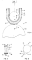
- Fig. 4 is a schematic, side elevation view of an apparatus for causing short fibers to project from one of the belt surfaces according to the present invention;
- Fig. 5 is a schematic end view of a system wherein a V-ribbed belt is used to drive a flat pulley; and
- Fig. 6 is a schematic, side elevation view of the system in Fig. 5.
- In Figs. 1 and 2, V-ribbed belts are shown with the present invention incorporated therein. The V-ribbed
belt 10 in Fig. 1 has one form of the invention incorporated therein. The V-ribbed belt 10' in Fig. 2 has another form of the invention incorporated therein. Thebelts 10, 10' have the same basic structure. Consequently, the parts of the belt 10' in Fig. 2 will be numbered the same as the corresponding parts of thebelt 10 in Fig. 1, with the exception of the addition of a " ' " after each reference numeral. - The
belt 10 has abody 12 within which a plurality of laterally spaced, longitudinally extending,load carrying cords 14 are embedded. The load carryingcords 14 are made from a low elongation, high strength rope made from polyester, aromatic polyamide fiber, or the like. The load carryingcords 14 are embedded in anadhesive rubber layer 16 made of one, or a blending of, NR, SBR, or CR. - One or more canvas layers 18 (one shown) having rubber coated, woven warp and weft threads are laminated over each other and bonded to the
outside surface 20 of thebody 12. - The
body 12 defines acompression section 22 within which a plurality of laterally spaced, longitudinally extending, V-shaped ribs 24 are formed. Theribs 24 are made from the same rubber material that defines theadhesive rubber layer 16. - According to the invention, the
ribs 24 are made with at least two distinct layers, with there being a first, insidelayer 26 and a second,outside layer 28, which abuts to theinside layer 26. Theinside layer 26 hasfibers 30 embedded therein. Theoutside layer 28 hasfibers 32 embedded therein. As described in greater detail below, the orientation of thefibers separate layers - The
inside layer 26 has a thickness H, taken in a direction between the inside and the outside of thebelt 10, that is 10 to 30% of the overall height H1 of theribs 24. - The
fibers 30 in thelayer 26 are preferably made from one of nylon, vinylon, polyester or aromatic polyamide or mixed threads of cotton or pulp with one or more of the above synthetic fibers. - The
fibers 30 have a length of 3 to 10 mm and are present in an amount of 5 to 30 weight parts offiber 30 for each 100 weight parts of rubber. Thefibers 30 are aligned so that their length is substantially parallel to the length of the belt. Preferably, the line of thefibers 30 does not deviate by more than 30° with respect to the length of the belt. - The
outside layer 28, which abuts to theinside layer 26 and extends from theinside layer 26 to the outside of theribs 24, hasfibers 32 therein in the same concentration as thefibers 30 in thelayer 26, i.e. 5 to 30 weight parts offiber 32 for each 100 weight parts of rubber. Thefibers 32 also have the same composition as thefibers 30. However, thefibers 32 have their lengths aligned in a direction transverse, and preferably substantially perpendicular to thefibers 30 and the length of thebelt 10. - The
fibers 30 in thebelt 10 are exposed at theinside surface 34 of thebelt 10. The primary difference between the belt 10' in Fig. 2 and thebelt 10 in Fig. 1 is that the fibers 30' in the belt 10' are caused to project from the inside belt surface 34'. - With both belts, the coefficient of friction between the inside surfaces 34, 34' on the cooperating pulley is reduced. With the belt 10' in Fig. 2, the coefficient of friction is reduced to a greater extent than for the
belt 10 in Fig. 1. - Fig. 3 shows a two-sided V-ribbed
belt 36 withload carrying cords 38 defining a belt neutral axis, a plurality of V-shapedribs 40 on one side of the belt neutral axis, and a plurality of V-shapedribs 42 on the other side of the neutral axis. - The
ribs 42 are constructed in substantially the same manner as the ribs 24' on the belt 10' in Fig. 2. That is, there is afirst layer 44, with longitudinally extendingfibers 46 embedded therein and projecting therefrom, and asecond layer 48 with laterally extendingfibers 50 embedded therein. - The
ribs 40 have the same general construction as theribs 42 with the exception that they face oppositely and are on the opposite side of theload carrying cords 38. That is, there is athird layer 52 with longitudinally extendingfibers 54 embedded therein and projecting therefrom. Thelayer 52 abuts to afourth layer 56, which has laterally extendingfibers 58 embedded therein. The principle of operation of thebelt 36 is the same as for thebelts 10, 10', with all the advantages of the inventive structure being realized therefrom. - Fig. 4 schematically shows a system at 60 for grinding the
belts 10', 36 so as to cause the projection offibers - For purposes of illustration, the belt 10' is shown mounted around a pair of
shafts 62, 64 in inside-out orientation. A grinding wheel 66 is pressed against the inside surface 34' of the ribs 24'. The main grinding shaft 62 and grinding wheel 66 are both rotated in a clockwise direction, as indicated by thearrows 68, 70. Alternatively, the grinding wheel 66 could be rotated in a counterclockwise direction, with the main grinding shaft 62 rotated in a clockwise direction. The grinding wheel 66 causes the fibers 30' to be drawn away from the surface 34', as seen in Fig. 4. The grinding wheel 66 scrapes the free ends of the fibers 30' off of the surface 34' as the grinding step is carried out. - It has been found that if the lengths of the fibers 30' make greater than a 30° angle with the length of the belt 10', an excessive amount of these fibers 30' are scraped completely off of the belt 10' with a system like that 60 in Fig. 4. As a consequence, the benefits of friction reduction are not realized.
- While the
belts belts belts - The
system 72 has a ribbedpulley 74 which, through thebelt 10, 10', drives aflat pulley 76. Aflat pulley 78 is used to tension an unsupported portion 80 of thebelt 10, 10' trained around thepulleys - In one such system, the
belt 10, 10' is slidable in the direction of the double-headed arrow 82 relative to the drivenpulley 76. - The
drive pulley 74 has a diameter of 14 to 16 mm and is driven at 1800 rpm. The drivenpulley 76 has a diameter of 500 to 600 mm and a width W of 300 mm. The tensioningpulley 78 has a diameter of 30 mm. Thebelt 10, 10' used with thissystem 72 has a width of 4 mm. Thebelt 10, 10' is engaged by pulleys on both sides thereof and can be positively driven through a small diameter drivepulley 74 so that rotation is imparted to the largerflat pulley 76. - With the
belt 10, 10' driving/being driven by a flat pulley, such as thepulley 76 in Figs. 5 and 6, it has been found that it is important to make thelayer 26, 26' to have a thickness H equal to at least 10% of the height of theribs 24, 24'. Thelayer 26, 26' is abraded significantly by the cooperatingsurface 84 on thepulley 76. Once thelayer 26, 26' wears significantly, the sound limiting benefits of the invention diminish significantly. - It has been found that if the
layer 26, 26' is made to have a thickness greater than 30% of the height of theribs 24, 24', thebelt 10, 10' becomes too rigid. As the morerigid belt 10, 10' bends, there is a risk of cracks developing in thelayer 26, 26'. - With the inventive structure, when the V-ribbed
belt 10, 10' cooperates with pulleys having cooperating grooves, thefibers 32, 32' in thelayers 28, 28' afford the necessary rigidity to theribs 24, 24' in a lateral direction as applied through the pulleys. When the V-ribbedbelt 10, 10' is wound around flat pulleys to operate as a flat belt, thefibers 30, 30', which are exposed and/or project from theribs 24, 24', reduce the friction coefficient between thebelt 10, 10' and a cooperating flat pulley surface, to thereby avoid generation of harsh, grating stick slip noise. - The foregoing disclosure of specific embodiments is intended to be illustrative of the broad concepts comprehended by the invention.
Claims (14)
- A power transmission belt (10) comprising:an elongate body (12) having a compression section (22);a first plurality (30) of short fibers embedded in the compression section (22) of the body (12) and aligned substantially longitudinally with respect to the body (12); anda second plurality (32) of short fibers embedded in the compression section (22) of the body (12) and aligned transversely with respect to the body (12), wherein the belt (10) has inside (34) and outside (18,20) surfaces characterised in that fibers in the first plurality (30) of fibers comprise exposed fibers which are exposed at the inside surface (34) of the belt (10), and fibers in the first plurality (30) of fibers comprise projecting fibers 30' which project from the inside surface (34) of the belt.
- The power transmission belt according to claim 1 wherein the projecting fibers project from between 0.1 to 3.0 mm from the inside surface (34) of the belt.
- The power transmission belt according to claim 1 or claim 2 wherein the first plurality (30) of short fibers is embedded in a first layer (26) in the compression section (22) and the second plurality (32) of short fibers is embedded in a second layer (28) in the compression section (22).
- The power transmission belt according to claim 3 wherein the first layer (26) has a dimension between the inside (34) and outside (18,20) of the belt (10) that is less than the dimension of the second layer (28) between the inside (34) and outside (18,20) of the belt (10).
- The power transmission belt according to claim 3 or claim 4 wherein the first (26) and second (28) layers abut to each other.
- The power transmission belt according to any one of claims 3-5 wherein a longitudinally extending rib (24) is defined by the body (12), the rib (24) has a height between the inside (34) and outside (18,20) surfaces of the belt (10), and the dimension of the first layer (26) between the inside (34) and outside (18,20) of the belt (10) is from 10-30% of the height of the rib (24).
- The power transmission belt according to any preceding claim wherein the belt (10) is a V-ribbed belt.
- The power transmission belt according to any preceding claim wherein the first plurality (30) of short fibers is aligned to make an angle of no more than 30° with the longitudinal direction of the belt body (12).
- The power transmission belt according to any preceding claim wherein fibers in the first plurality (30) of fibers have a length of 3-10 mm.
- The power transmission belt according to any preceding claim wherein the first plurality (30) of fibers is embedded in a rubber layer (26) and the first plurality (30) of fibers is present in an amount between 5-30 weight parts per 100 weight parts of rubber in said layer (26).
- The power transmission belt according to any preceding claim wherein fibers in the first plurality (30) of fibers are made from at least one of a) nylon, b) vinylon, c) polyester, d) aromatic polyamide, e) mixed threads of cotton and at least one of nylon, vinylon, polyester and aromatic polyamide, and f) mixed threads of pulp and at least one of nylon, vinylon, polyester and aromatic polyamide.
- The power transmission belt according to any preceding claim wherein the exposed fibers are exposed over from 50-95% of the area of the inside surface (34) of the belt.
- The power transmission belt according to any preceding claim wherein the belt is a double-ribbed belt (36) with inside and outside surfaces and having a neutral axis and longitudinally extending ribs (40,42) both inside and outside of the neutral axis, said first (46) and second plurality (50) of short fibers being inside the neutral axis, there being a third plurality (54) of short fibers embedded in a third layer (52) outside of the neutral axis and a fourth plurality (58) of short fibers embedded in a fourth layer (56) outside of the neutral axis, said third plurality (54) of fibers aligned substantially longitudinally with respect to the belt (36), said fourth plurality (58) of fibers aligned transversely with respect to the belt (36).
- The power transmission belt according to claim 13 wherein the third layer (52) is outside of the fourth layer (56) and exposed at the outside of the belt (36), there being fibers in the third plurality (54) of fibers exposed at the outside of the belt (36).
Applications Claiming Priority (2)
| Application Number | Priority Date | Filing Date | Title |
|---|---|---|---|
| JP82725/92 | 1992-11-04 | ||
| JP1992082725U JP2558070Y2 (en) | 1992-11-04 | 1992-11-04 | V-ribbed belt |
Publications (2)
| Publication Number | Publication Date |
|---|---|
| EP0596713A1 EP0596713A1 (en) | 1994-05-11 |
| EP0596713B1 true EP0596713B1 (en) | 1997-05-21 |
Family
ID=13782398
Family Applications (1)
| Application Number | Title | Priority Date | Filing Date |
|---|---|---|---|
| EP93308774A Expired - Lifetime EP0596713B1 (en) | 1992-11-04 | 1993-11-03 | V-ribbed belt |
Country Status (5)
| Country | Link |
|---|---|
| US (1) | US5415594A (en) |
| EP (1) | EP0596713B1 (en) |
| JP (1) | JP2558070Y2 (en) |
| CA (1) | CA2102246C (en) |
| DE (1) | DE69310868T2 (en) |
Families Citing this family (26)
| Publication number | Priority date | Publication date | Assignee | Title |
|---|---|---|---|---|
| US5624338A (en) * | 1994-07-27 | 1997-04-29 | Mitsuboshi Belting Ltd. | Double V-ribbed belt |
| US5498213A (en) * | 1994-12-15 | 1996-03-12 | Mitsuboshi Belting Ltd. | Power transmission belt |
| US5704862A (en) * | 1997-01-13 | 1998-01-06 | The Goodyear Tire & Rubber Company | Dual sided poly-V drive belt and pulley therefor |
| US6361462B1 (en) * | 1997-10-31 | 2002-03-26 | Mitsuboshi Belting Ltd. | V-ribbed power transmission belt |
| CA2313421A1 (en) | 1999-08-26 | 2001-02-26 | The Goodyear Tire & Rubber Company | Power transmission belt |
| US6464607B1 (en) * | 1999-12-15 | 2002-10-15 | The Goodyear Tire & Rubber Company | Power transmission belt |
| US6672983B2 (en) | 2000-12-21 | 2004-01-06 | The Goodyear Tire & Rubber Company | Power transmission drive system |
| US6802117B2 (en) * | 2001-02-05 | 2004-10-12 | George Dalisay | Device for circuit board insertion and extraction |
| DE10240988B4 (en) * | 2002-09-05 | 2014-02-27 | Inventio Ag | Elevator installation with a belt and pulley drive transmission arrangement |
| EP1449474A1 (en) * | 2003-02-22 | 2004-08-25 | Vorwerk & Co. Interholding GmbH | Brush roll disposed in a carpet sweeper and coupling of a driving and driven part |
| JP2005069358A (en) | 2003-08-25 | 2005-03-17 | Bando Chem Ind Ltd | Friction transmission belt and manufacturing method thereof |
| DE102006007509B4 (en) * | 2006-02-16 | 2009-01-22 | Contitech Antriebssysteme Gmbh | V-ribbed belt with improved noise behavior |
| US9506527B2 (en) * | 2006-04-07 | 2016-11-29 | Gates Corporation | Power transmission belt |
| US8357065B2 (en) | 2006-06-01 | 2013-01-22 | The Gates Corporation | Power transmission belt and a process for its manufacture |
| US20080135343A1 (en) * | 2006-08-11 | 2008-06-12 | Ernst Ach | Elevator support means for an elevator system, elevator system with such an elevator support means and method for assembling such an elevator system |
| EP1886957A1 (en) * | 2006-08-11 | 2008-02-13 | Inventio Ag | Lift belt for a lift system and method for manufacturing such a lift belt |
| JP2008044791A (en) * | 2006-08-11 | 2008-02-28 | Inventio Ag | Elevator support means of elevator system, elevator system having the elevator support means, and method of assembling the elevator system |
| EP2125594A2 (en) * | 2007-03-12 | 2009-12-02 | Inventio Ag | Elevator system, carrying means for an elevator system, and method for the production of a carrying means |
| WO2009075729A2 (en) * | 2007-12-05 | 2009-06-18 | The Gates Corporation | Power transmission belt |
| JP4989556B2 (en) * | 2008-05-26 | 2012-08-01 | 三ツ星ベルト株式会社 | V-ribbed belt |
| DE102009012395A1 (en) * | 2009-03-10 | 2010-09-16 | Siegfried Reichenbach | toothed belt |
| US20130190120A1 (en) * | 2009-04-30 | 2013-07-25 | The Gates Corporation | Double cogged v-belt for variable speed drive |
| US8206251B2 (en) * | 2009-04-30 | 2012-06-26 | The Gates Corporation | Double cogged V-belt for variable speed drive |
| JP5863712B2 (en) * | 2013-02-21 | 2016-02-17 | バンドー化学株式会社 | Auxiliary drive belt transmission for automobile and V-ribbed belt used therefor |
| US9157503B2 (en) * | 2013-03-14 | 2015-10-13 | Dayco Ip Holdings, Llc | V-ribbed belt with spaced rib flank reinforcement |
| DE102017215654A1 (en) * | 2017-09-06 | 2019-03-07 | Contitech Antriebssysteme Gmbh | Drive belt with a profiled belt back |
Family Cites Families (13)
| Publication number | Priority date | Publication date | Assignee | Title |
|---|---|---|---|---|
| US249404A (en) * | 1881-11-08 | Rufus e | ||
| IT1176829B (en) * | 1984-09-27 | 1987-08-18 | Pirelli | TRAPEZOIDAL BELT |
| DK8604319A (en) * | 1985-09-13 | 1987-03-14 | ||
| DE3535676A1 (en) * | 1985-10-05 | 1987-05-07 | Continental Gummi Werke Ag | Driving belt, in particular a grooved belt |
| IT1186158B (en) * | 1985-12-20 | 1987-11-18 | Pirelli Transmissioni Ind Spa | TRAPEZOIDAL BELT, IN PARTICULAR FOR CONTINUOUS SPEED VARIATORS |
| IT1188682B (en) * | 1986-05-21 | 1988-01-20 | Pirelli | FLEXIBLE BELT AND RELATED TRANSMISSION |
| JPS62199553U (en) * | 1986-06-09 | 1987-12-18 | ||
| JPS63157552U (en) * | 1987-03-31 | 1988-10-17 | ||
| US4798566A (en) * | 1987-11-19 | 1989-01-17 | The Gates Rubber Company | Power transmission belt |
| US4904232A (en) * | 1988-10-31 | 1990-02-27 | Mitsuboshi Belting, Ltd. | Power transmission belt |
| US5197928A (en) * | 1989-11-20 | 1993-03-30 | Mitsuboshi Belting Ltd. | V-ribbed belt having protruding fibers |
| JPH0786377B2 (en) * | 1990-01-31 | 1995-09-20 | 三ツ星ベルト株式会社 | V belt |
| JP3127849U (en) * | 2006-10-03 | 2006-12-14 | 進 須藤 | Food packaging |
-
1992
- 1992-11-04 JP JP1992082725U patent/JP2558070Y2/en not_active Expired - Fee Related
-
1993
- 1993-11-02 CA CA002102246A patent/CA2102246C/en not_active Expired - Fee Related
- 1993-11-03 EP EP93308774A patent/EP0596713B1/en not_active Expired - Lifetime
- 1993-11-03 DE DE69310868T patent/DE69310868T2/en not_active Expired - Lifetime
- 1993-11-03 US US08/147,117 patent/US5415594A/en not_active Expired - Lifetime
Also Published As
| Publication number | Publication date |
|---|---|
| EP0596713A1 (en) | 1994-05-11 |
| US5415594A (en) | 1995-05-16 |
| DE69310868D1 (en) | 1997-06-26 |
| CA2102246C (en) | 1997-06-24 |
| CA2102246A1 (en) | 1994-05-05 |
| JP2558070Y2 (en) | 1997-12-17 |
| JPH0640497U (en) | 1994-05-31 |
| DE69310868T2 (en) | 1998-01-08 |
Similar Documents
| Publication | Publication Date | Title |
|---|---|---|
| EP0596713B1 (en) | V-ribbed belt | |
| EP0633408B1 (en) | V-ribbed belt | |
| US5197928A (en) | V-ribbed belt having protruding fibers | |
| US20060105874A1 (en) | Timing belt | |
| US5120281A (en) | Power transmission belt | |
| US5624338A (en) | Double V-ribbed belt | |
| US4265627A (en) | Power transmission belt | |
| JPH07117124B2 (en) | Power transmission belt | |
| EP0514002B1 (en) | V-ribbed belt | |
| US4504258A (en) | Power transmission belt | |
| EP0429299B1 (en) | V-ribbed belt and method of fabricating the same | |
| AU2002237915B2 (en) | Endless power transmission belt | |
| AU2002237915A1 (en) | Endless power transmission belt | |
| US6626784B1 (en) | Low modulus belt | |
| US5427637A (en) | V-ribbed belt and method of fabricating the same | |
| US5358453A (en) | Cogged v-belt | |
| EP0040908B1 (en) | Power transmission belt | |
| JPS5924684B2 (en) | Endless belt for conveying paper sheets | |
| JP2848516B2 (en) | V-ribbed belt | |
| CN220118572U (en) | Transmission belt | |
| JPH0110514Y2 (en) | ||
| JP2740753B2 (en) | Toothed belt and method of manufacturing the same | |
| JPS596278Y2 (en) | V-belt | |
| EP0119335A1 (en) | Power transmission belt | |
| CA1213451A (en) | V-belt for power transmission |
Legal Events
| Date | Code | Title | Description |
|---|---|---|---|
| PUAI | Public reference made under article 153(3) epc to a published international application that has entered the european phase |
Free format text: ORIGINAL CODE: 0009012 |
|
| AK | Designated contracting states |
Kind code of ref document: A1 Designated state(s): DE FR GB |
|
| 17P | Request for examination filed |
Effective date: 19940726 |
|
| 17Q | First examination report despatched |
Effective date: 19950706 |
|
| GRAG | Despatch of communication of intention to grant |
Free format text: ORIGINAL CODE: EPIDOS AGRA |
|
| GRAH | Despatch of communication of intention to grant a patent |
Free format text: ORIGINAL CODE: EPIDOS IGRA |
|
| GRAH | Despatch of communication of intention to grant a patent |
Free format text: ORIGINAL CODE: EPIDOS IGRA |
|
| GRAA | (expected) grant |
Free format text: ORIGINAL CODE: 0009210 |
|
| AK | Designated contracting states |
Kind code of ref document: B1 Designated state(s): DE FR GB |
|
| REF | Corresponds to: |
Ref document number: 69310868 Country of ref document: DE Date of ref document: 19970626 |
|
| ET | Fr: translation filed | ||
| PLBE | No opposition filed within time limit |
Free format text: ORIGINAL CODE: 0009261 |
|
| STAA | Information on the status of an ep patent application or granted ep patent |
Free format text: STATUS: NO OPPOSITION FILED WITHIN TIME LIMIT |
|
| 26N | No opposition filed | ||
| REG | Reference to a national code |
Ref country code: GB Ref legal event code: IF02 |
|
| PGFP | Annual fee paid to national office [announced via postgrant information from national office to epo] |
Ref country code: DE Payment date: 20101126 Year of fee payment: 18 |
|
| PGFP | Annual fee paid to national office [announced via postgrant information from national office to epo] |
Ref country code: GB Payment date: 20101124 Year of fee payment: 18 |
|
| PGFP | Annual fee paid to national office [announced via postgrant information from national office to epo] |
Ref country code: FR Payment date: 20111128 Year of fee payment: 19 |
|
| GBPC | Gb: european patent ceased through non-payment of renewal fee |
Effective date: 20121103 |
|
| REG | Reference to a national code |
Ref country code: FR Ref legal event code: ST Effective date: 20130731 |
|
| REG | Reference to a national code |
Ref country code: DE Ref legal event code: R119 Ref document number: 69310868 Country of ref document: DE Effective date: 20130601 |
|
| PG25 | Lapsed in a contracting state [announced via postgrant information from national office to epo] |
Ref country code: DE Free format text: LAPSE BECAUSE OF NON-PAYMENT OF DUE FEES Effective date: 20130601 |
|
| PG25 | Lapsed in a contracting state [announced via postgrant information from national office to epo] |
Ref country code: GB Free format text: LAPSE BECAUSE OF NON-PAYMENT OF DUE FEES Effective date: 20121103 Ref country code: FR Free format text: LAPSE BECAUSE OF NON-PAYMENT OF DUE FEES Effective date: 20121130 |
|
| REG | Reference to a national code |
Ref country code: DE Ref legal event code: R082 Ref document number: 69310868 Country of ref document: DE Representative=s name: KOTITSCHKE & HEURUNG PARTNERSCHAFT, DE |