EP0594884A1 - Werkstückförderer - Google Patents
Werkstückförderer Download PDFInfo
- Publication number
- EP0594884A1 EP0594884A1 EP92118536A EP92118536A EP0594884A1 EP 0594884 A1 EP0594884 A1 EP 0594884A1 EP 92118536 A EP92118536 A EP 92118536A EP 92118536 A EP92118536 A EP 92118536A EP 0594884 A1 EP0594884 A1 EP 0594884A1
- Authority
- EP
- European Patent Office
- Prior art keywords
- conveyor
- main body
- rail
- panel
- runners
- Prior art date
- Legal status (The legal status is an assumption and is not a legal conclusion. Google has not performed a legal analysis and makes no representation as to the accuracy of the status listed.)
- Granted
Links
Images


Classifications
-
- B—PERFORMING OPERATIONS; TRANSPORTING
- B62—LAND VEHICLES FOR TRAVELLING OTHERWISE THAN ON RAILS
- B62D—MOTOR VEHICLES; TRAILERS
- B62D65/00—Designing, manufacturing, e.g. assembling, facilitating disassembly, or structurally modifying motor vehicles or trailers, not otherwise provided for
- B62D65/02—Joining sub-units or components to, or positioning sub-units or components with respect to, body shell or other sub-units or components
- B62D65/18—Transportation, conveyor or haulage systems specially adapted for motor vehicle or trailer assembly lines
-
- Y—GENERAL TAGGING OF NEW TECHNOLOGICAL DEVELOPMENTS; GENERAL TAGGING OF CROSS-SECTIONAL TECHNOLOGIES SPANNING OVER SEVERAL SECTIONS OF THE IPC; TECHNICAL SUBJECTS COVERED BY FORMER USPC CROSS-REFERENCE ART COLLECTIONS [XRACs] AND DIGESTS
- Y10—TECHNICAL SUBJECTS COVERED BY FORMER USPC
- Y10T—TECHNICAL SUBJECTS COVERED BY FORMER US CLASSIFICATION
- Y10T29/00—Metal working
- Y10T29/53—Means to assemble or disassemble
- Y10T29/53539—Means to assemble or disassemble including work conveyor
- Y10T29/53543—Means to assemble or disassemble including work conveyor including transporting track
- Y10T29/53548—Means to assemble or disassemble including work conveyor including transporting track and work carrying vehicle
Definitions
- This invention relates to a work conveyor for feeding panel components to a vehicle body assembly line or the like, for example, from a panel component production line, in which panel components for various portions of each vehicle body are produced, in a main vehicle body assembly line in which the panel components are assembled into a vehicle body by welding, and especially to a work conveyor useful as an apparatus for simultaneously feeding a left side panel and a right side panel in combination to the main vehicle body assembly line at a predetermined position.
- vehicle body components are fed in succession to a floor panel conveyor line and are welded on each floor panel as a base to assemble the vehicle body.
- vehicle body components especially those assembled in combination as a left component and a right component, for example, side panels are simultaneously fed in combination as a left side panel and a right side panel to predetermined locations of the floor panel and are welded on the floor panel.
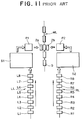
- left and right side panels 2a,2b to be fed to a main body assembly line ML, in which floor panels 5 are conveyed, are transported through different routes to feed positions arranged on both sides of the main body assembly line ML as will be described hereinafter.
- Each left side panel 2a is assembled in a left side panel production line LL and the left side panel 2a so completed is conveyed on a pallet (not shown) from a last step L8 of the left side panel production line LL to a storage S1 which serves as a component storage area.
- a predetermined number of left side panels 2a are stored there.
- a worker feeds by a forklift truck the leading left side panel 2a, which has been stored in the storage S1 and is mounted on the pallet, to a left side panel feed position P1 arranged alongside the main body assembly line ML.
- Symbols L1-L8 shown along the left side panel production line LL designate work stations for various production steps.
- each right side panel 2b produced in a right side panel production line RL is conveyed on a pallet (not shown) from a last step R8 of the left side panel production line RL to a storage S2.
- the leading right side panel 2b is fed by the worker from the storage S2 to a right side panel feed position P2 arranged alongside the main body assembly line ML.
- Symbols R1-R8 shown along the right side panel production line RL designate work stations for various production steps.
- the left and right side panels 2a,2b fed to the left and right side panel feed positions P1,P2 arranged on both sides of the main body assembly line ML are held by unillustrated feed means and then fed to the main body assembly line ML at positions adjacent to the floor panel 5.
- the present invention has the following objects:
- a work conveyor for successively transporting components to a main body assembly line in which vehicle bodies are assembled one after another.
- the work conveyor comprises: a vertical lifter for upwardly transporting each component from a receiving position, where the vertical lifter receives the component, to a delivery position arranged above the receiving position for delivering the component; conveyor means having a conveyor rail, which is formed in a loop and includes a cut-off portion formed by cutting itself off at least at a portion thereof, and a plurality of runners arranged movably on the conveyor rail, each of said runners having a hanger disposed thereon to receive one of the components from the vertical lifter; control means electrically connected to the respective runners for outputting running control signals to each of the runners so that the runner is stopped at least at a work transfer position, where the runner receives one of the components from the vertical lifter, and at a standby position arranged before the cut-off portion; a traverser having a transport rail disposed extending from the cut-off portion to
- a work conveyor for successively transporting panel components, which are used as panel components for vehicle bodies, to a main body assembly line (ML) in which the vehicle bodies are assembled one after another.
- the work conveyor comprises: a panel component conveyor connecting together a plurality of work stations arranged along a panel component production line, in which the panel components are produced, to transport panel components worked at each of the work stations toward a downstream side of the panel component production line; a vertical lifter for upwardly transporting each panel component from a receiving position, where the vertical lifter receives the panel component, to a delivery position arranged above the receiving position for delivering the panel component; a trolley conveyor having a conveyor rail, which is formed in a loop, includes a cut-off portion formed by cutting itself off at least at a portion thereof and has plural types of insulated trolley lines, and a plurality of runners arranged on the conveyor rail and movable upon receipt of the electric signals from the trolley lines, each of said runners having a hanger disposed thereon and provided with arms
- a work conveyor for simultaneously transporting a left panel component and a right panel component in combination from corresponding two panel component production lines, in which two types of panel components used as left and right panel components for vehicle bodies are produced respectively, to a predetermined position in a main body assembly line in which various vehicle body components fed thereto are assembled into vehicle bodies.
- the work conveyor comprises: two panel component conveyors arranged in the respective panel component production lines and connecting together plural work stations arranged along the individual panel component production lines, whereby a panel component worked at each of the work stations in each of the panel component production lines is conveyed to the next work station on a downstream side of the panel component production line; two vertical lifters disposed adjacent to the respective panel component conveyors and vertically reciprocal between receiving positions, where the vertical lifters receive the panel components from the corresponding panel component conveyors, and delivery positions arranged above the receiving positions to deliver the panel components; a trolley conveyor having conveyor rails extending in parallel combination, each of said conveyor rails being formed in a loop, including a cut-off portion formed by cutting itself off at least at a portion thereof and having plural types of insulated trolley lines; and a plurality of runners arranged on each of the conveyor rails and movable upon receipt of the electric signals from the trolley lines, each of said runners having a hanger disposed thereon and provided with arms closable to hold the panel component transported to the corresponding delivery position by
- the present invention has overcome the above-described inconvenience of the conventional work conveyors and has achieved the objects of the present invention.
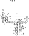
- FIG. 1 there are shown a left side panel production line LL arranged linearly on a floor F (see FIG. 2) of a plant to produce left side panels 2a (see FIG. 7).
- Designated at symbols L1-L8 are individual work stations, and symbol L9 indicates a delivery station arranged at a below-described work transfer position 1A to deliver each work, i.e., left side panel which has been conveyed to the delivery station.
- Symbol RL indicates a right side panel production line arranged in parallel with the left side panel production line LL to produce right side panels 2b (see FIG. 7.).
- the right side panel production line RL has work stations R1-R8 and a delivery station R9.
- Designated at numeral 1 is a trolley conveyor.
- Symbols 1a,1b indicate rails provided in combination at an elevated height to serve as conveyance paths for conveying different panel components, respectively.
- These rails 1a,1b are formed substantially in a loop, and are arranged such that they extend through positions (i.e., the work transfer position 1A and a work transfer position 1B) above the delivery station L9 of the left side panel production line LL and the delivery station R9 of the right side panel production line RL and also pass through a runner transfer position 1D arranged adjacent to a below-described main body assembly line ML.
- the rails 1a,1b are each provided with plural runners 10 which are constructed to run by itself upon receipt of power supply from power lines (see FIG.
- the runners 10 are each provided with a hanger (see FIG. 4) to suspend a work therefrom.
- a running truck for the corresponding runners 10 is divided into plural sections so that running of each runner 10 is controlled via the rail 1a or 1b in the individual sections.
- Each runner 10 is controlled so that it stops at the work transfer positions 1A,1B and the runner transfer position 1D. It is also controlled to stop at a standby position 1C which is arranged before the runner transfer position 1D.
- Each runner 10 running through the sections of the corresponding rail 1a or 1b is also controlled in such a way that the runner 10 is allowed to run continuously when there is no other runner 10 in the section ahead of the section in which the first-mentioned runner 10 is running but is stopped in the section in which the runner 10 is running when there is another runner 10 in the section ahead of the current section.
- Numeral 3 designates a drop lifter arranged at a side panel feed station where the left and right side panels 2a,2b are fed to the main body assembly line ML.
- the drop lifter 3 receives the left and right side panels 2a,2b, which have been conveyed at an elevated height, and lowers them to the main body assembly line ML provided on the floor F.
- Indicated at symbol TR is a traverser provided extending between the runner transfer position 1, which is arranged at the rails 1a,1b of the trolley conveyor 1, and the position above the main body assembly line ML. At this position, the drop lifter 3 is also arranged.
- the traverser TR receives the runners 10,10, which have been conveyed to the standby position 1C of the rails 1a,1b of the trolley conveyor 1 and stopped there and hold the left and right side panels 2a,2b, respectively, with the left and right side panels 2a,2b still held by the corresponding runners 10,10; conveys the runners 10,10 to the position above the main body assembly line ML, namely, to the drop lifter 3; simultaneously transfer the left and side panels 1a,1b in combination to the drop lifter 3; and then returns the runners 10,10 from the position of the drop lifter 3 to the positions of the rails 1a,1b to allow the runners 10,10 to run again on the rails 1a,1b, respectively.
- the drop lifter 3 which has received the left and right side panels 2a,2b in combination from the corresponding runners 10,10, descends to the level of the main body assembly line ML and feeds the left and right side panels 2a,2b to opposite sides of a floor panel 5 conveyed in the main body assembly line ML.
- the left and right side panels 2a,2b fed to the opposite sides of the floor panel 5 are then raised in directions perpendicular to the floor panel 5 and, in states held in the specified positions, are conveyed to the next step for their assembly by welding.
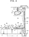
- the left side panel production line LL and the right side panel production line RL will now be described with reference to FIGS. 1 and 2.
- both the side panel production lines LL,RL are substantially of the same construction, only one of the production lines, namely, only the right side panel production line RL will be described.
- the right side panel production line RL is composed of plural work stations R1-R9 arranged at the same intervals on a straight line.
- parts which make up the right side panel 2b are successively assembled by unillustrated industrial robots on a right side panel main body in accordance with an assembling method such as welding.
- the conveyance of each work, i.e., assembly through the individual work stations is conducted by a shuttle conveyor 11 which extends from the first work station R1 to the delivery station R9 arranged at the work transfer position 1B.
- This shuttle conveyor 11 is provided, as depicted in FIG.
- each pallet 111 located at the individual work stations R1-R8 are conveyed to the next stations at the same time by the shuttle conveyor 11 which is designed to reciprocate at a conveyance stroke set equal to a distance ST between each two adjacent work stations.
- Each pallet 111 is provided with plural locators 111a which support the right side panel 2b as a work in a prescribed position.
- Each pallet 111 which has been conveyed to the last work station R9 is again returned to the first work station R1 by an unillustrated conveyor means.
- a lifter 120 which transfers the right side panel 2b as a work from the shuttle conveyor 11 in the right side panel production line RL to the trolley conveyor 1.
- the lifter 120 comprises two columns 121 provided side by side on the floor F in a direction extending at a right angle relative to the direction of conveyance of each work in the right side panel production line RL; a vertical guide rail 122 provided along the columns 121; a lift member 124 provided for vertical movement along the posts 121 while being guided by the guide rail 122; a movable frame 125 horizontally extending from the lift member 124 toward the shuttle conveyor 11 in the right side panel production line RL; plural cylinders 126 arranged on the movable frame 125 and having rods 126a extendible toward an interior space of the frame 125; locators 126b provided at free ends of the individual rods 126a for holding the right side panel 2b as a work in a prescribed position; and a lifting means 123 disposed on upper end portions of the columns 121 and provided with a sprocket 123a which carries and drives a chain 123b connected at one end thereof to the lift member 124 and at an opposite end thereof to a weight
- the plural cylinders 126 are controlled depending on the kind of each work and are hence applicable to a wide variety of works.
- the locator 126b of each cylinder 126 is constructed movably between an operated position, where the locator 126b supports the right side panel 2b, and a non-operated position where the locator 126b is retreated from the work.
- the lift member 124 is movable up and down by the lifting means 123 between a lower position, namely, the work receiving position where the lift member 124 receives the right side panel 2b from the shuttle conveyor 11 and an upper position, namely, the work transfer position where the lift member 124 transfers the right side panel 2b to the trolley conveyor 1.
- the lifter for transferring each left side panel 2a from the left side panel production line to the trolley conveyor 1 is of the same construction as the above-described lifter 120, so that its description is omitted herein.
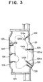
- the trolley conveyor 1 will next be described with reference to FIGS. 1 and 4-6. A description will first be made of the rails 1a,1b.
- the rails 1a,1b are each constructed of a turned square U-shaped, stationary frame 12, a rail main body 13 disposed inside the turned square U-shaped, stationary frame 12, and plural insulated trolley lines 14 arranged longitudinally within the rail main body 13.
- the rail main body 13 has a rear wall 13a and bent walls 13b,13b, all of which form vertical surfaces, respectively, and a top wall which presents a horizontal surface.
- Each runner 10 is provided with a drive roller 17, a driven roller 18 and plural guide rollers 19 as will be described subsequently herein.
- the drive roller 17 and the driven roller 18 roll on the horizontal top wall, while the guide rollers 19 rolls on the rear wall 13a and the bent walls 13b,13b.
- the insulated trolley lines 14 are composed of three power lines, one ground line and two control lines.
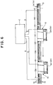
- the six insulated trolley lines 14 which are provided as a unit are divided into sections 13A,13B,13C,13D,.... set over predetermined lengths along the length of the rail main body 13 as shown in FIG. 6, so that they become independent from one section to another.
- the insulated trolley lines 14 provided in the individual sections are connected to a ground control panel C arranged on the floor F. A description will next be made of each runner 10.
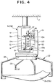
- Numeral 15 indicates a housing of the runner 10.
- a motor 16 is secured on an upper front part of the casing 15 as viewed in the advancing direction.
- the drive roller 17 is mounted on a drive shaft of the motor 16 and is maintained in rolling contact with the upper wall of the rail main body 13.
- the driven roller 18, on the other hand, is secured on an upper rear part of the casing 15 as viewed in the advancing direction such that the driven roller 18 is also maintained in rolling contact with the upper wall of the rail main body 13.
- the plural guide rollers 19 are rotatably supported on the housing 15 at positions adjacent to the drive roller 17 and the driven roller 18.
- These guide rollers 19 are maintained in rolling contact with the rear wall 13a and bent walls 13b,13b of the rail main body 13 so that, while the runner 10 is moving by itself along the rain main body 13, the guide rollers 19 hold the rain main body 13 from both left and right sides to prevent the runner 10 from shaking or meandering during running.
- a control unit 20 is also mounted on the housing 15. This control unit 20 is provided with brushes 21 which are maintained in sliding contact with the individual lines of the six insulated trolley lines 14, whereby electric power supplied from the ground control panel C is fed to the control unit 20 of the runner 10 and motor drive signals sent from the ground control panel C are introduced into the control unit 20.
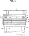
- the housing 15 is also provided with a hanger 22.
- This hanger 22 is formed of plural turnable arms 23.
- left and right side panels 3L,3R of a car family A as well as left and right side panels 4L,4R of another car family B can be both held in a horizontal position by selectively turning the arms 23 (see FIG. 5).
- the rail main body 13 is divided into the plural sections 13A,13B,13C,3D, .... in accordance with the insulated trolley lines 14.
- a signal indicating the presence of the runner 10 in the Section 13A is outputted to the ground control panel C via the control lines upon contact of the brushes 21 of the runner 10 with the power lines of the insulated trolley lines 14 arranged in the section 13A.
- the ground control panel C stops output of a running command signal, which commands running of another runner 10, to the control lines of the insulated trolley lines 14 in the section 13B which is located behind the section 13A.
- the runner 10 positioned in the section D which is on the right-hand side in FIG. 6, namely, on the rear side as viewed in the advancing direction, is allowed to advance to the section 13B by a running command signal inputted to the section 13C from the ground control panel C because no runner 10 is present in the section 13B ahead of the section 13C.
- a signal from the section 13A the runner 10 is then stopped in the section 13B.
- the trolley conveyor 1 is constructed to have plural runners 10 run along the rails 1a,1b while checking the state of the front parts of the rails 1a,1b as viewed in the advancing direction, namely, while confirming the existence of other runners in the advancing direction.
- the above-described trolley conveyor 1 is arranged, as is illustrated in FIG. 1, to permit conveyance of the left and right side panels 2a,2b, which are different works from each other, to the corresponding rails 1a,1b arranged in combination and substantially in parallel.
- the runners 10 which run on the respective rails 1a,1b are controlled to stop, in the running paths formed by the rails 1a,1b, at the work transfer positions 1A,1B, where the runners 10 receive the corresponding works from the left and right side panel production lines LL,RL, respectively, and at the standby position 1D where the runners 10 wait for their loading on the traverser 31.
- the traverser TR will next be described with reference to FIGS. 7-10.
- symbols 1a,1b indicate the rails arranged in combination at an elevated height as illustrated in FIG. 1.
- the rail main bodies 13,13 are cut off to form cut-off portions 30,30.
- the traverser TR is provided as depicted in FIGS. 8-10.
- the cut-off portions 30,30 are provided with a pair of straight rails 32,32 which extend at right angles relative to the rails 1a,1b.
- the straight rails 32,32 are provided above the rail main bodies 13,13 of the rails 1a,1b.
- One ends of the straight rails 32,32 are located in the cut-off portions 30,30 of the rails 1a,1b whereas the other ends extend to the position above the main body assembly line ML.
- a traverser main body 31 of the under hung type is reciprocally supported on the straight rails 32,32.
- a reversible motor 33 is provided centrally on the traverser main body 31.
- Drive shafts 34,34 of the motor 33 are provided with drive rollers 35,35 which roll on the straight rails 32,32, respectively, whereby the traverser main body 31 is reciprocated by the drive rollers 35,35 along the straight rails 32,32.
- connecting rails 36,36 Attached to a lower side of the traverser main body 31 are a pair of connecting rails 36,36 arranged at the same interval as the rail main bodies 13,13 of the rails 1a,1b provided in combination in the above-described trolley conveyor 1. These connecting rails 36,36 serve to connect the rails 1a,1b at the cut-off portions 30,30, respectively.
- the connecting rails 36,36 have a similar construction to the rail main bodies 13,13 of the above-described trolley conveyor 1, namely, are each provided internally with six insulated trolley lines (not shown) electrically connected to the ground control panel C.
- hanger closing mechanisms 37,37 On the lower side of the traverser main body 31, there are also provided hanger closing mechanisms 37,37, hanger opening mechanisms 39,39 and hanger locking mechanisms 39,39 in opposition to the hangers 22,22, respectively.
- the traverser TR is constructed to load the runners 10,10, which have been conveyed to the cut-off portions 30,30 by the trolley conveyor 1, on the connecting rails 36,36 together with the side panels 2a,2b held by the runners 10,10 and then to convey the runners 10,10 with the side panels 2a,2a still held thereby to the position above the main body assembly line ML.
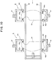
- the drop lifter 6 is constructed of two posts 61,61 provided on one side of the main body assembly line ML, two posts 61,61 arranged on the other side of the main body assembly line ML, elevator members 62,62,62,62 provided for vertical movement along the respective posts 61,61,61,61, and work receivers 62a,62a,.... attached to and extending from free end portions of the individual elevator members 62,62,62, 62.
- the elevator members 62,62, 62,62 are arranged for vertical movement between an upper position, where the elevator members 62,62,62,62,62 receive the works, i.e., the left and right side panels 2a,2b simultaneously from the traverser TR. and a lower position where the elevator members 62,62,62,62 transfer the left and right side panels 2a,2b simultaneously to the work conveyor 4 in the main body assembly line ML arranged on the floor F.
- the left side panel 2a and the right side panel 2b are produced in the different production lines, namely, in the left side panel production line LL and the right side panel production line RL, respectively.
- the each of the lines LL,RL say, in the right side panel production line RL, works, namely, assemblies are successively conveyed to the downstream-side work stations R2-R9 from one station to the next at the predetermined conveyance stroke ST and are progressively formed into the right side panels 2b by unillustrated industrial robots disposed at the respective work stations R1-R9.
- the left and right side panels 2a,2b completed as described above are conveyed to and stopped at the delivery stations L9,R9 which are arranged as the last stations of the respective side panel production lines LL,RL at the work transfer positions 1A,1B depicted in FIG. 1.
- the corresponding runner 10 in the trolley conveyor 1 Before the right side panel 2b is conveyed to the last station R9 in the right side panel production line RL, the corresponding runner 10 in the trolley conveyor 1 has advanced to the transfer position 1B, has stopped at the predetermined point in the transfer position 1B and has been on standby with the arms 23 thereof opened.
- the associated lifter 12 causes the lift member 124 to downwardly move from the upper position (the position indicated by two-dot chain lines in FIG. 2) to the work receiving position at the lower position (the position indicated by solid lines in the same figure).
- the plural cylinders 126 provided on the movable frame 125 are all held at the non-operated positions.
- the lift member 124 When the lift member 124 reaches the work receiving position, only the cylinders 126 corresponding to the type of the right side panel 2b out of the cylinders 126 are actuated to drive the associated rods 126a to positions where the right side panel 2b can be supported by the locators 126b provided at the free end portions of the rods 126a. In this state, the lift member 124 is moved upwards and is stopped at the position where the arms 23 of the runner 10 can hold the right side panel 2b. The arms 23 of the runner 10 are then closed to hold the right side panel 2b. The runner 10 has now received the right side panel 2b from the lifter 12.
- each runner 10 with the right side panel 2b received from the lifter 12 receives a running command signal from the ground control panel C through the control line of the insulated trolley lines 14 provided on the rail main body 13, so that the runner 10 runs toward the standby position 1C forwardly ahead in the advancing direction.
- the running of the runner 10 is also controlled by a control signal sent via the ground control panel C from the section ahead of the section in which the runner 10 itself is present.
- the running of the runner 10 is controlled in such a way that the running 10 is allowed to run to the standby position 1C without stopping on the way when no other runner 10 is present in front of the runner 10 itself but, when another runner 10 is present in front of the runner 10 itself, is stopped in the section one section behind the section where said another runner 10 is located.
- the runners 10 each of which is holding the right side panel 2b are arranged from one section to another in a row on the rail 1b with the first runner 10 located in the standby position 1C while waiting for conveyance to the traverser TR.
- the trolley conveyor 1 has not only the function to convey each right side panel 2b through the sections from the transfer position 1B to the standby position 1C but also the storage function to enable feeding of each right side panel 2b as a work to the next step in conformity with the production cycle time of the next step.
- each left side panel 2a to the standby position 1C is exactly the same as the conveyance of the right side panel 2b described above, so that its description is omitted herein.
- the left and right side panels 2a,2b conveyed to the standby position 1C by the runners 10,10, which run along the rails 1a,1b provided in combination, are loaded, in the state held on the runners 10,10, on the connecting rails 36,36 provided on the traverser main body 31 of the traverser TR and are then stopped on the connecting rails 36,36.
- the traverser main body 31 While being driven by the motor 33 and guided along the straight rails 32,32, the traverser main body 31 then runs toward the main body assembly line ML and stops at the position above the main body assembly line ML.
- the hanger opening mechanisms 38,38 provided on the traverser TR are actuated to open the arms 23 of the runners 10,10 so that the left and right side panels 2a,2b are transferred onto the corresponding work receivers 62,62a,.... of the drop lifter 6.
- the elevator members 62,62,62,62 of the drop lifter 6 are driven downwardly to simultaneously feed the left and right side panels 2a,2b to the opposite sides of the floor panel 5.
- the traverser TR actuates the hanger closing mechanisms 37,37 subsequent to the transfer of the left and right side panels 2a,2b to the drop lifter 6 so that the arms 23 of the runners 10,10 located on the connecting rails 36,36 are brought into closed positions, respectively.
- the traverser main body 31 moves along the straight rails 32,32 to the home positions on the rails 1a,1b of the trolley conveyor 1, namely, to the runner transfer position 1D.
- the runners 10,10 which are located on the connecting rails 36,36 of the traverser 31 without holding any work thereon, return to the corresponding rails 1a,1b and are then driven toward the transfer positions 1A,1B to receive the next works, respectively.
Landscapes
- Engineering & Computer Science (AREA)
- Manufacturing & Machinery (AREA)
- Chemical & Material Sciences (AREA)
- Combustion & Propulsion (AREA)
- Transportation (AREA)
- Mechanical Engineering (AREA)
- Automatic Assembly (AREA)
- Automobile Manufacture Line, Endless Track Vehicle, Trailer (AREA)
Priority Applications (3)
| Application Number | Priority Date | Filing Date | Title |
|---|---|---|---|
| US07/966,755 US5297483A (en) | 1992-10-28 | 1992-10-28 | Work conveyor |
| DE1992624384 DE69224384T2 (de) | 1992-10-29 | 1992-10-29 | Werkstückförderer |
| EP92118536A EP0594884B1 (de) | 1992-10-28 | 1992-10-29 | Werkstückförderer |
Applications Claiming Priority (2)
| Application Number | Priority Date | Filing Date | Title |
|---|---|---|---|
| US07/966,755 US5297483A (en) | 1992-10-28 | 1992-10-28 | Work conveyor |
| EP92118536A EP0594884B1 (de) | 1992-10-28 | 1992-10-29 | Werkstückförderer |
Publications (2)
| Publication Number | Publication Date |
|---|---|
| EP0594884A1 true EP0594884A1 (de) | 1994-05-04 |
| EP0594884B1 EP0594884B1 (de) | 1998-02-04 |
Family
ID=26131153
Family Applications (1)
| Application Number | Title | Priority Date | Filing Date |
|---|---|---|---|
| EP92118536A Expired - Lifetime EP0594884B1 (de) | 1992-10-28 | 1992-10-29 | Werkstückförderer |
Country Status (2)
| Country | Link |
|---|---|
| US (1) | US5297483A (de) |
| EP (1) | EP0594884B1 (de) |
Cited By (2)
| Publication number | Priority date | Publication date | Assignee | Title |
|---|---|---|---|---|
| WO1999037526A1 (de) * | 1998-01-26 | 1999-07-29 | Thyssen Krupp Industries Ag | Verfahren zur herstellung von türen, klappen oder einzelteilen aus blech im kfz-karosserierohbau |
| IT201900017438A1 (it) * | 2019-09-27 | 2021-03-27 | Ocm S P A | Sistema di trasporto |
Families Citing this family (7)
| Publication number | Priority date | Publication date | Assignee | Title |
|---|---|---|---|---|
| DE19626966A1 (de) * | 1996-07-04 | 1998-01-08 | Cegelec Aeg Anlagen Und Automa | Spurgeführtes Transportsystem mit Transportfahrzeugen |
| JP3949248B2 (ja) * | 1997-12-26 | 2007-07-25 | 本田技研工業株式会社 | 自動車用ドアの組立ライン |
| JP4978052B2 (ja) * | 2005-11-09 | 2012-07-18 | 日産自動車株式会社 | ワーク搬送装置およびワーク搬送方法 |
| US8051544B2 (en) * | 2007-12-24 | 2011-11-08 | Haverfield International Incorporated | Method of replacing insulators on a tower and insulator support and transport assembly therefor |
| KR20090105759A (ko) | 2008-04-03 | 2009-10-07 | 현대자동차주식회사 | 자동차용 플로워 생산시스템 |
| JP5454491B2 (ja) * | 2011-02-25 | 2014-03-26 | 株式会社安川電機 | 作業システム |
| DE102021102764A1 (de) * | 2020-02-19 | 2021-08-19 | Daido Kogyo Co., Ltd. | Profilwalzvorrichtung und verfahren zur herstellung eines faserverstärkten kunststoff-profilwalzteils |
Citations (3)
| Publication number | Priority date | Publication date | Assignee | Title |
|---|---|---|---|---|
| GB2176445A (en) * | 1985-06-21 | 1986-12-31 | Fata Europ Group | Plant for mounting vehicle doors |
| US4685208A (en) * | 1984-11-15 | 1987-08-11 | Mazda Motor Corporation | Apparatus for assembling vehicle bodies |
| DE9209686U1 (de) * | 1992-07-15 | 1992-09-10 | KUKA Schweissanlagen GmbH, 86165 Augsburg | Bearbeitungsstation für Fahrzeugkarosserien in einer Transferlinie |
Family Cites Families (5)
| Publication number | Priority date | Publication date | Assignee | Title |
|---|---|---|---|---|
| US2969750A (en) * | 1957-12-06 | 1961-01-31 | Udylite Corp | Rack loading and unloading mechanism |
| US4766547A (en) * | 1986-04-14 | 1988-08-23 | Transfer Technologies, Inc. | Computer controlled conveyor system |
| EP0347586B1 (de) * | 1988-06-18 | 1993-12-08 | Focke & Co. (GmbH & Co.) | Vorrichtung zum Transport von Verpackungsmaterial zu einer Verpackungsmaschine |
| US5236156A (en) * | 1988-10-20 | 1993-08-17 | Buro Patent Ag | Monitoring of track-type conveyor system |
| US5119732A (en) * | 1991-01-18 | 1992-06-09 | R.R. Donnelley & Sons Company | Portable gantry robot |
-
1992
- 1992-10-28 US US07/966,755 patent/US5297483A/en not_active Expired - Lifetime
- 1992-10-29 EP EP92118536A patent/EP0594884B1/de not_active Expired - Lifetime
Patent Citations (3)
| Publication number | Priority date | Publication date | Assignee | Title |
|---|---|---|---|---|
| US4685208A (en) * | 1984-11-15 | 1987-08-11 | Mazda Motor Corporation | Apparatus for assembling vehicle bodies |
| GB2176445A (en) * | 1985-06-21 | 1986-12-31 | Fata Europ Group | Plant for mounting vehicle doors |
| DE9209686U1 (de) * | 1992-07-15 | 1992-09-10 | KUKA Schweissanlagen GmbH, 86165 Augsburg | Bearbeitungsstation für Fahrzeugkarosserien in einer Transferlinie |
Non-Patent Citations (1)
| Title |
|---|
| FöRDERN UND HEBEN vol. 22, no. 7, May 1972, pages 386 - 389 'SYNCHRONISIERTE MONTAGESTRASSEN' * |
Cited By (3)
| Publication number | Priority date | Publication date | Assignee | Title |
|---|---|---|---|---|
| WO1999037526A1 (de) * | 1998-01-26 | 1999-07-29 | Thyssen Krupp Industries Ag | Verfahren zur herstellung von türen, klappen oder einzelteilen aus blech im kfz-karosserierohbau |
| IT201900017438A1 (it) * | 2019-09-27 | 2021-03-27 | Ocm S P A | Sistema di trasporto |
| WO2021058799A1 (en) * | 2019-09-27 | 2021-04-01 | Ocm S.P.A. | Conveyor system |
Also Published As
| Publication number | Publication date |
|---|---|
| US5297483A (en) | 1994-03-29 |
| EP0594884B1 (de) | 1998-02-04 |
Similar Documents
| Publication | Publication Date | Title |
|---|---|---|
| US4738387A (en) | Flexible manufacturing system for the processing and production of multi-part subassemblies, in particular subassemblies of semi-finished vehicle bodies | |
| US7695235B1 (en) | Automated warehousing and cargo loading system | |
| US6799673B2 (en) | Versaroll overhead conveyor system | |
| JPH05337760A (ja) | ワーク搬送システム及び該システムに好適に用いられるパレット搬送装置 | |
| US5297483A (en) | Work conveyor | |
| US4671402A (en) | Free flow conveyor | |
| US4609093A (en) | Hanger conveyance in automobile assembly line | |
| KR100879070B1 (ko) | 대차 이송 장치 | |
| KR101850379B1 (ko) | 기계식 주차 운반기 생산 시스템 및 그 방법 | |
| CN217200402U (zh) | 一种自动化上料系统 | |
| US5437529A (en) | Conveying system | |
| JPH0243127A (ja) | 車輌組立ラインにおける下部品の供給装置 | |
| JP2007269483A (ja) | パレット搬送装置 | |
| KR970007124B1 (ko) | 워크 반송장치 | |
| JPH0219050B2 (de) | ||
| CN217707384U (zh) | 一种纵梁出库输送系统 | |
| JP2999601B2 (ja) | ワーク入出庫制御装置 | |
| JP2618531B2 (ja) | 住宅ユニット生産ライン | |
| JPH0444491Y2 (de) | ||
| KR100435667B1 (ko) | 차량용 사이드 아우터 어셈블리 시스템 | |
| JPH1130051A (ja) | 被格納物収納装置 | |
| JPH0350004Y2 (de) | ||
| JP2555066Y2 (ja) | ボディー構成部品の搬送装置 | |
| JP2534800B2 (ja) | 住宅ユニット生産ライン | |
| JPH0225586Y2 (de) |
Legal Events
| Date | Code | Title | Description |
|---|---|---|---|
| PUAI | Public reference made under article 153(3) epc to a published international application that has entered the european phase |
Free format text: ORIGINAL CODE: 0009012 |
|
| 17P | Request for examination filed |
Effective date: 19921029 |
|
| AK | Designated contracting states |
Kind code of ref document: A1 Designated state(s): DE NL |
|
| 17Q | First examination report despatched |
Effective date: 19960102 |
|
| GRAG | Despatch of communication of intention to grant |
Free format text: ORIGINAL CODE: EPIDOS AGRA |
|
| GRAH | Despatch of communication of intention to grant a patent |
Free format text: ORIGINAL CODE: EPIDOS IGRA |
|
| GRAH | Despatch of communication of intention to grant a patent |
Free format text: ORIGINAL CODE: EPIDOS IGRA |
|
| GRAA | (expected) grant |
Free format text: ORIGINAL CODE: 0009210 |
|
| AK | Designated contracting states |
Kind code of ref document: B1 Designated state(s): DE NL |
|
| REF | Corresponds to: |
Ref document number: 69224384 Country of ref document: DE Date of ref document: 19980312 |
|
| PLBE | No opposition filed within time limit |
Free format text: ORIGINAL CODE: 0009261 |
|
| STAA | Information on the status of an ep patent application or granted ep patent |
Free format text: STATUS: NO OPPOSITION FILED WITHIN TIME LIMIT |
|
| 26N | No opposition filed | ||
| PGFP | Annual fee paid to national office [announced via postgrant information from national office to epo] |
Ref country code: DE Payment date: 19991102 Year of fee payment: 8 |
|
| PG25 | Lapsed in a contracting state [announced via postgrant information from national office to epo] |
Ref country code: DE Free format text: LAPSE BECAUSE OF NON-PAYMENT OF DUE FEES Effective date: 20010703 |
|
| PGFP | Annual fee paid to national office [announced via postgrant information from national office to epo] |
Ref country code: NL Payment date: 20031008 Year of fee payment: 12 |
|
| PG25 | Lapsed in a contracting state [announced via postgrant information from national office to epo] |
Ref country code: NL Free format text: LAPSE BECAUSE OF NON-PAYMENT OF DUE FEES Effective date: 20050501 |
|
| NLV4 | Nl: lapsed or anulled due to non-payment of the annual fee |
Effective date: 20050501 |