EP0592925A1 - Handgefahrenmelder - Google Patents
Handgefahrenmelder Download PDFInfo
- Publication number
- EP0592925A1 EP0592925A1 EP93116095A EP93116095A EP0592925A1 EP 0592925 A1 EP0592925 A1 EP 0592925A1 EP 93116095 A EP93116095 A EP 93116095A EP 93116095 A EP93116095 A EP 93116095A EP 0592925 A1 EP0592925 A1 EP 0592925A1
- Authority
- EP
- European Patent Office
- Prior art keywords
- detector
- operating lever
- button
- spring
- detector according
- Prior art date
- Legal status (The legal status is an assumption and is not a legal conclusion. Google has not performed a legal analysis and makes no representation as to the accuracy of the status listed.)
- Granted
Links
Images

Classifications
-
- G—PHYSICS
- G08—SIGNALLING
- G08B—SIGNALLING OR CALLING SYSTEMS; ORDER TELEGRAPHS; ALARM SYSTEMS
- G08B25/00—Alarm systems in which the location of the alarm condition is signalled to a central station, e.g. fire or police telegraphic systems
- G08B25/12—Manually actuated calamity alarm transmitting arrangements emergency non-personal manually actuated alarm, activators, e.g. details of alarm push buttons mounted on an infrastructure
-
- H—ELECTRICITY
- H01—ELECTRIC ELEMENTS
- H01H—ELECTRIC SWITCHES; RELAYS; SELECTORS; EMERGENCY PROTECTIVE DEVICES
- H01H3/00—Mechanisms for operating contacts
- H01H3/02—Operating parts, i.e. for operating driving mechanism by a mechanical force external to the switch
- H01H3/022—Emergency operating parts, e.g. for stop-switch in dangerous conditions
- H01H2003/0233—Emergency operating parts, e.g. for stop-switch in dangerous conditions for alarm triggering, e.g. fire alarm, emergency off switches operated by breaking a glass
Definitions
- the invention relates to a manual hazard detector according to the preamble of claim 1.
- detectors for manual actuation namely manual danger detectors
- push-button detectors Such detectors are usually manufactured in two versions.
- the detector type B is an indirect actuation, a so-called push button version.
- a glass pane must be broken in and the push button pressed, i.e. the trigger element is the button (control element).
- the button pops out by spring pressure, i.e. the release element is formed by the disc (fragile element) plus the button (control element).
- an electric switch is actuated by the push of a button, which forwards the alarm message as an electrical signal to the hazard alarm system. It is extremely important that these detectors function properly and are always ready for a safe alarm.
- the push button In the known push button detector (type B), the push button is pressed in after breaking the glass pane. A bevel attached to the push button pushes a beveled switch button and thereby triggers the alarm signal.
- Such a switching mechanism with this type Power transmission and deflection is common in precision engineering, but in the present case, when unfavorable circumstances come together, e.g. unfavorable tolerance, rough surface of the sliding surfaces due to production-related or subsequent dusting or one-sided button operation, it can lead to difficulties in triggering the alarm.
- the object of the invention is to further develop the manual hazard detectors described at the outset in such a way that the switching or actuating mechanism ensures reliable alarming, regardless of mechanical friction forces and manufacturing tolerances, and can optionally be used in the detector variants described above (type A or type B).
- the manual hazard detector the housing of which usually has a detector door, a fragile element and a detector insert, which has a printed circuit board or a supporting element, at least one switch, an actuating device with an associated compression spring and a detector pan, between the printed circuit board or the carrier part and the tub has a newly designed fastening mechanism, which has an operating lever that is fixed on one side but rotatably mounted, a control button protruding through the tub and on the other side a resilient element that is assigned to a switch button of a switch.
- the invention has the advantage that the friction-dependent deflection of force at the switch button by 90 o is eliminated because it has a directly acting mechanism that is independent of friction and tolerance. Safe switch actuation is also possible thanks to a tolerance-independent button attachment and guidance.
- the resilient element can expediently be formed by a leaf spring which is attached to the operating lever.
- the leaf spring can have a longitudinal section, so that the two leaf spring ends can each actuate a switching element.
- the operating lever, the operating element and the resilient element can be formed in one piece, for example from resilient plastic.
- the resilient element can be formed by a multi-angled spring plate which is fastened to the operating lever by means of a pivot bearing.
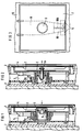
- Fig. 1 the basic structure of a known push button detector, i.e. a manual hazard detector for indirect actuation (type B) is shown.
- a manual hazard detector for indirect actuation type B
- the push button 3 is pressed in the direction of the arrow.
- the bevel 3a on the push button 3 presses the beveled switch button 5a and thereby triggers the alarm signal.
- FIG. 2 the basic structure of a known spring button detector (detector type A) for direct actuation is shown.
- the spring button 3 with the beveled shift gate 3a is extended by a resilient pin 6a.
- the spring pin 6a lies against the glass pane 4 and holds the spring button 3 in the pressed position, so that the switch button 5a is held in this standby position.
- the spring button 3 is pressed outward in the direction of the arrow by the compression spring 6 and the switch button 5a of the switch 5 is released for triggering the alarm signal.
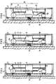
- the manual hazard detector according to the invention has a newly designed actuating mechanism 19 which is formed by the operating lever 9, the operating element 3 and the resilient element, here a leaf spring 10.
- a trough 7 is placed on the printed circuit board 8 with one or more pressure switches 5 - two are shown here.
- the control lever 9, the control element 3 (button) and, as a resilient element, the leaf spring 10 are located between the trough 7 and the printed circuit board 8.
- the control lever 9 is fixed on the upper side and rotatably mounted (FIG. 9a).
- the leaf spring 10 made of spring plate is attached to the operating lever 9, for example with a snap connection.
- the leaf spring 10 is longitudinally slotted in this exemplary embodiment (FIG. 10b).
- a compression spring 6 holds the actuation button or the control element 3, the control lever 9 and the leaf spring 10 in the rest position, ie the indirectly actuated detector is ready for operation in the rest position.
- detector type A control element 3 rests on the glass pane, ie on fragile element 4 (FIG.).
- the trough 7 forms the counterpart for the control element 3.
- actuating mechanism 19 is in one piece, e.g. as a molded plastic part, i.e. the operating lever 9, the operating element 3 and the resilient element 12 are made from one piece and form the actuating mechanism 19.
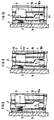
- FIGS. 7a, 7b and 7c A further embodiment of the invention is shown in FIGS. 7a, 7b and 7c. 4 and 5, a spring plate 11 is provided instead of the leaf spring 10, which is rotatably attached to the operating lever 9 by means of a rotary bearing 9c.
- the spring plate 11 can only bend to one side.
- Fig. 7a shows the basic structure
- Fig.7b and 7c the function
- Fig. 7b shows the directly operated detector type A
- Fig.7c shows the indirectly operated detector type B.
- 8 and 9 show two different embodiments for a directly operated detector (type A).
- 8 shows a so-called spring button detector, after which the glass spring 4 (fragile element), the compression spring 6 presses the spring button 3 (operating element) in the direction of the arrow.
- the leaf spring 10 is supported on the tub 7, whereby the free end 10a of the leaf spring 10 is moved in the opposite direction and actuates the pressure switch 5 on the printed circuit board 8, which leads to an alarm being triggered.
- the operating lever 9 can also be pressed in as far as possible by high impact energy. In this case, too, an alarm is triggered because the spring button detector also behaves like a push button detector.
- the operating lever is fixed in the alarm position, but this is not shown.
- Fig. 9 shows a so-called tilting glass version.
- the disc 4 breaks at the predetermined breaking point 4a (scoring on the inside of the disc in the middle of the button) and tilts in the pressure direction as shown.
- the control button 3 and the leaf spring 10 are moved in the direction of the arrow and the alarm is triggered.
- This type of direct activity is common in some European countries, e.g. Finland and England, common.
- a transparent film 4b can be inserted or glued on the pane on the outside of the detector in all versions.
- Fig. 10 there is again an indirectly operated detector, a so-called push-button version (type B).
- a so-called push-button version type B
- the leaf spring 10 presses directly on the switch button 5a of the switch 5 and triggers the alarm.
- the operating lever 4 is then fixed in the alarm position by a bolt, not shown here.
Landscapes
- Business, Economics & Management (AREA)
- Emergency Management (AREA)
- Physics & Mathematics (AREA)
- General Physics & Mathematics (AREA)
- Push-Button Switches (AREA)
- Emergency Alarm Devices (AREA)
- Rotary Switch, Piano Key Switch, And Lever Switch (AREA)
- Burglar Alarm Systems (AREA)
- Geophysics And Detection Of Objects (AREA)
- Power-Operated Mechanisms For Wings (AREA)
Abstract
Description
- Die Erfindung bezieht sich auf einen Handgefahrenmelder gemäß dem Oberbegriff des Anspruchs 1.
- In Gefahrenmeldeanlagen für Feuer- oder Polizeinotruf werden neben automatischen Meldern auch Melder für eine manuelle Betätigung, nämlich Handgefahrenmelder, sogenannte "Druckknopfmelder" verwendet. Derartige Melder werden üblicherweise in zwei Ausführungen hergestellt. Der Meldertyp B stellt eine indirekte Betätigung, eine sogenannte Druckknopfausführung dar. Dabei ist eine Glasscheibe einzuschlagen und dann der Druckknopf zu drücken, d.h. das Auslöseelement ist der Knopf (Bedienelement). Beim Meldertyp A für eine direkte Betätigung, eine sogenannte Springknopfausführung, muß lediglich die Glasscheibe eingeschlagen werden, dann springt der Knopf durch Federdruck heraus, d.h. das Auslöseelement ist von der Scheibe (zerbrechliches Element) plus dem Knopf (Bedienelement) gebildet. In beiden Fällen wird durch die Knopfbewegung ein elektrischer Schalter betätigt, welcher die Alarmmeldung als elektrisches Signal an die Gefahrenmeldeanlage weiterleitet. Dabei ist es außerordentlich wichtig, daß diese Melder einwandfrei funktionieren und jederzeit für eine sichere Alarmgabe einsatzbereit sind.
- Bei dem bekannten Druckknopfmelder (Typ B) wird nach dem Zerbrechen der Glasscheibe der Druckknopf eingedrückt. Dabei drückt eine am Druckknopf angebrachte Schräge einen angeschrägten Schalterknopf und löst dadurch das Alarmsignal aus. Eine derartige Schaltmechanik mit dieser Art der Kraftübertragung und Umlenkung ist in der Feinwerktechnik allgemein üblich, kann jedoch im vorliegenden Fall beim Zusammentreffen ungünstiger Umstände, z.B. ungünstige Toleranzlage, rauhe Oberfläche der Gleitflächen durch fertigungsbedingte oder nachträgliche Verstaubung oder einseitige Knopfbetätigung, zu Schwierigkeiten bei der Alarmauslösung führen.
- Diese Problematik ist auch beim Springknopfmelder (Typ A) gegeben. Bei dem bekannten Springknopfmelder mit einer abgeschrägten Schaltkulisse ist der Springknopf durch einen federnden Stift verlängert, der an der Glasscheibe anliegt und den Springknopf in der gedrückten Stellung hält, so daß der Schalterknopf des Schalters in dieser Bereitschaftsstellung gehalten wird. Für die Alarmgabe, d.h. Einschlagen der Scheibe, wird der Springknopf durch die Druckfeder herausgedrückt und der Schalterknopf des Schalters für das Auslösen des Alarmsignals freigegeben. Diese Ausführungsform erfordert eine kostenaufwendige Ergänzung des Knopfes und weist die gleichen Probleme wie der Meldertyp B auf.
- Aufgabe der Erfindung ist es, eingangs geschilderte Handgefahrenmelder derart weiterzubilden, daß die Schalt- bzw. Betätigungsmechanik unabhängig von mechanischen Reibungskräften und Fertigungstoleranzen eine zuverlässige Alarmgabe sicherstellt und wahlweise in den oben beschriebenen Meldervarianten (Typ A oder Typ B) verwendet werden kann.
- Diese Aufgabe wird erfindungsgemäß mit den Merkmalen des Anspruchs 1 gelöst.
- Der Handgefahrenmelder, dessen Gehäuse üblicherweise eine Meldertür, ein zerbrechliches Element und einen Meldereinsatz aufweist, welcher eine Leiterplatte bzw. ein Tragelement, mindestens einen Schalter, eine Betätigungsvorrichtung mit einer zugeordneten Druckfeder sowie eine Melderwanne besitzt, weist erfindungsgemäß zwischen der Leiterplatte bzw. dem Trägerteil und der Wanne eine neu gestaltete Befestigungsmechanik auf, die von einem Bedienhebel, der an der einen Seite fixiert aber drehbar gelagert ist, einen durch die Wanne nach vorne ragenden Bedienknopf und an der anderen Seite ein federndes Element auf, welches einen Schalterknopf eines Schalters zugeordnet ist.
- Die Erfindung hat den Vorteil, daß die reibungsabhängige Kraftumlenkung am Schalterknopf um 90o entfällt, weil sie eine direkt wirkende reibungs- und toleranzunabhängige Mechanik aufweist. Ebenso ist eine sichere Schalterbetätigung durch eine toleranzunabhängige Knopfbefestigung und -führung möglich.
- Zweckmäßigerweise kann das federnde Element von einer Blattfeder gebildet sein, welche am Bedienhebel befestigt ist. Dabei kann die Blattfeder einen Längsschnitt aufweisen, so daß die beiden Blattfederenden je ein Schaltelement betätigen können.
- In einer besonderen Ausgestaltung der Erfindung kann der Bedienhebel, das Bedienelement und das federnde Element einstückig, z.B. aus federndem Kunststoff, gebildet sein. In einer weiteren vorteilhaften Ausgestaltung der Erfindung kann das federnde Element von einem mehrfach abgewinkelten Federblech gebildet sein, das mittels eines Drehlagers am Bedienhebel befestigt ist.
- Weitere Vorteile und Ausgestaltungsmöglichkeiten der Erfindung ergeben sich in der folgenden Beschreibung an mehreren Ausführungsbeispielen, die anhand der Zeichnung erläutert werden. Dabei zeigen
- Fig. 1 einen bekannten Druckknopfmelder im Schnitt,
- Fig. 2 einen bekannten Springknopfmelder im Schnitt,
- Fig. 3 im Ausschnitt einen erfindungsgemäßen Melder in Frontansicht,
- Fig. 4 im Schnitt ein Ausführungsbeispiel des erfindungsgemäßen Melders für direkte Betätigung,
- Fig. 5 im Schnitt ein Ausführungsbeispiel des erfindungsgemäßen Melders für indirekte Betätigung
- Fig. 6 eine abgewandelte Ausführungsform,
- Fig. 7a eine weitere Ausführungsform für direkte Betätigung,
- Fig. 7b eine abgewandelte Ausführungsform für direkte Betätigung und
- Fig. 7c eine Ausführungsform für die indirekte Betätigung,
- Fig. 8 eine weitere Ausführungsform für direkte Betätigung als Springknopfmelder,
- Fig. 9 eine Ausführungsform in Kippglasausführung und
- Fig. 10 eine Ausführungsform für indirekte Betätigung.
- In Fig. 1 ist der prinzipielle Aufbau eines bekannten Druckknopfmelders, d.h. ein Handgefahrenmelder für indirekte Betätigung (Typ B) dargestellt. Im Alarmfall wird nach dem Zerbrechen der Glasscheibe 4 (zerbrechliches Element) der Druckknopf 3 in Pfeilrichtung gedrückt. Dabei drückt die Schräge 3a am Druckknopf 3 den angeschrägten Schalterknopf 5a und löst dadurch das Alarmsignal aus.
- In Fig. 2 ist der prinzipielle Aufbau eines bekannten Springknopfmelders (Meldertyp A) für direkte Betätigung dargestellt. Der Springknopf 3 mit der abgeschrägten Schaltkulisse 3a ist durch einen federnden Stift 6a verlängert. Der Federstift 6a liegt an der Glasscheibe 4 an und hält den Springknopf 3 in gedrückter Stellung, so daß der Schalterknopf 5a in dieser Bereitschaftsstellung gehalten wird. Im Alarmfall, d.h. beim Einschlagen der Scheibe 4, wird der Springknopf 3 durch die Druckfeder 6 in Pfeilrichtung nach außen gedrückt und der Schalterknopf 5a des Schalters 5 zum Auslösen des Alarmsignals freigegeben. Die oben geschilderten Nachteile bei diesen bekannten Meldertypen sind hier ersichtlich.
- Der erfindungsgemäße Handgefahrenmelder weist eine neu gestaltete Betätigungsmechanik 19 auf, die von dem Bedienhebel 9, dem Bedienelement 3 und dem federnden Element, hier einer Blattfeder 10, gebildet ist. Auf die Leiterplatte 8 mit einem oder mehreren Druckschaltern 5 - hier sind zwei dargestellt - ist eine Wanne 7 aufgesetzt. Zwischen der Wanne 7 und der Leiterplatte 8 befinden sich der Bedienhebel 9, das Bedienelement 3 (Knopf) und als federndes Element die Blattfeder 10. Der Bedienhebel 9 ist an der oberen Seite fixiert und drehbar gelagert (9a). Die Blattfeder 10 aus Federblech ist am Bedienhebel 9 befestigt, beispielsweise mit einer Schnappverbindung. Um die Schalterbetätigungskraft bei Einsatz von mehreren Schaltern 5 annähernd gleich groß zu gestalten, ist bei diesem Ausführungsbeispiel die Blattfeder 10 längsgeschlitzt (10b). Eine Druckfeder 6 hält den Betätigungsknopf bzw. das Bedienelement 3, den Bedienhebel 9 und die Blattfeder 10 in der Ruhelage, d.h. der indirekt betätigte Melder ist in der Ruhelage betriebsbereit. (Fig.3 und 4). Das Bedienelement 3 liegt beim Meldertyp A an der Glasscheibe, d.h. am zerbrechlichen Element 4, an (Fig.). Bei dem indirekt betätigten Melder, Typ B, gemäß Fig.5 bildet die Wanne 7 die Gegenlage für das Bedienelement 3.
- In Fig. 6 ist ein anders ausgestalteter erfindungsgemäßer Handgefahrenmelder für indirekte Betätigung, also Typ B, dargestellt. Dort ist die Betätigungsmechanik 19 einstückig, z.B. als Kunststoff-Spritzteil, ausgestaltet, d.h. der Bedienhebel 9, das Bedienelement 3 und das federnde Element 12 sind aus einem Stück gefertigt und bilden die Betätigungsmechanik 19.
- In den Fig.7a, 7b und 7c ist eine weitere Ausführungsform der Erfindung dargestellt. Dabei ist anstelle der Blattfeder 10 gemäß Fig.4 und 5 ein Federblech 11 vorgesehen, das am Bedienhebel 9 mittels eines Drehlagers 9c drehbar angebracht ist. In der hier dargestellten Form kann das Federblech 11 nur nach einer Seite hin abknicken. Fig. 7a zeigt den prinzipiellen Aufbau, die Fig.7b und 7c die Funktion, wobei Fig. 7b den direkt betätigten Meldertyp A und Fig.7c den indirekt betätigten Meldertyp B zeigt.
- In den Fig. 8 und 9 sind zwei verschiedene Ausführungsformen für einen direkt betätigten Melder (Typ A) dargestellt. Fig. 8 zeigt einen sogenannten Springknopfmelder, bei dem nach dem Einschlagen der Glasscheibe 4 (zerbrechliches Element) die Druckfeder 6 den Springknopf 3 (Bedienelement) in Pfeilrichtung drückt. Dabei stützt sich die Blattfeder 10 an der Wanne 7 ab, wodurch das freie Ende 10a der Blattfeder 10 in die entgegengesetzte Richtung bewegt wird und den Druckschalter 5 auf der Leiterplatte 8 betätigt, was zur Alarmauslösung führt. Beim Einschlagen der Scheibe 4 kann durch hohe Schlagenergie der Bedienhebel 9 auch bis zum Anschlag eingedrückt werden. Auch in diesem Fall wird ein Alarm ausgelöst, weil der Springknopfmelder sich auch wie ein Druckknopfmelder verhält. Auch hier wird - wie bei allen Ausführungsformen des erfindungsgemäßen Melders - der Bedienhebel in der Alarmstellung fixiert, was jedoch nicht dargestellt ist.
- Fig. 9 zeigt eine sogenannte Kippglas-Ausführung. Durch Druck auf die Scheibe 4 bricht diese an der vorgegebenen Sollbruchstelle 4a (Ritzung an der Scheibeninnenseite in Knopfmitte) und kippt wie dargestellt in Druckrichtung. Dabei werden der Bedienknopf 3 und die Blattfeder 10 in Pfeilrichtung bewegt und der Alarm ausgelöst. Diese Art der direkten Betätigung ist in einigen europäischen Ländern, wie z.B. Finnland und England, üblich. Zum Schutz vor Verletzungen kann bei allen Ausführungen auf der Scheibe auf der Melderaußenseite eine durchsichtige Folie 4b eingelegt oder aufgeklebt sein.
- In Fig.10 ist nochmals ein indirekt betätigter Melder, eine sogenannte Druckknopfausführung (Typ B) gezeigt. Nach dem Einschlagen der Glasscheibe 4 und Drücken des Betätigungsknopfes 3 drückt die Blattfeder 10 direkt auf den Schalterknopf 5a des Schalters 5 und löst den Alarm aus. Der Bedienhebel 4 wird anschließend durch einen hier nicht dargestellten Riegel in der Alarmstellung fixiert.
Claims (8)
- Handgefahrenmelder mit Meldergehäuse (1), Meldertür (2), zerbrechlichem Element (4) und einem Meldereinsatz, der ein Tragelement bzw. eine Leiterplatte (8), zumindest ein Schaltelement (5), eine Betätigungsvorrichtung (3), eine Druckfeder (6), die auf die Betätigungsvorrichtung (3) einwirkt, und eine Melderwanne (7) aufweist,
dadurch gekennzeichnet, daß zwischen der Leiterplatte bzw. dem Trägerteil (8) und der Wanne (7) eine Betätigungsmechanik (19) angeordnet ist, die von einem Bedienhebel (9), der an einer Seite fixiert und drehbar gelagert (9a) ist, von einem durch die Wanne (7) nach vorne ragendem Bedienelement (3) und (des Bedienhebels (9b)) von einem federnden Element (12) an der anderen Seite gebildet ist, wobei das federnde Element einem Schalterknopf (5a) des Schaltelements (5) zugeordnet ist. - Handgefahrenmelder nach Anspruch 1,
dadurch gekennzeichnet, daß das federnde Element (12) von einer am Bedienhebel (9) befestigten Blattfeder (10) gebildet ist. - Handgefahrenmelder nach Anspruch 2,
dadurch gekennzeichnet, daß die Blattfeder (10) einen Längsschnitt (10b) aufweist, und daß den beiden Blattfederenden je ein Schaltelement (5) zugeordnet ist. - Handgefahrenmelder nach Anspruch 1,
dadurch gekennzeichnet, daß der Bedienhebel (9), das Bedienelement (3) und das federnde Element (12) einstückig ausgebildet sind. - Handgefahrenmelder nach Anspruch 1 oder 2,
dadurch gekennzeichnet, daß das federnde Element (12) von einem mehrfach abgewinkelten Federblech (11) gebildet ist, welches mittels eines Drehlagers (9c) am Bedienhebel 9 befestigt ist. - Handgefahrenmelder nach einem der vorhergehenden Ansprüche, dadurch gekennzeichnet, daß für eine direkte Melderbetätigung (Typ A) das Bedienelement (3) als Springknopf ausgebildet ist, der gegen das zerbrechliche Element (4) gedrückt (6) ist.
- Handgefahrenmelder nach einem der vorhergehenden Ansprüche, dadurch gekennzeichnet, daß für eine direkte Melderbetätigung (Typ A) der Melder als Kippglasmelder ausgebildet ist, wobei das zerbrechliche Element (4) eine Sollbruchstelle (4a) aufweist, und das Befestigungselement (3) als Druckknopf ausgebildet ist, welcher der Sollbruchstelle (4a) direkt zugeordnet ist.
- Handgefahrenmelder nach einem der vorhergehenden Ansprüche, dadurch gekennzeichnet, daß für eine indirekte Melderbetätigung (Typ B) das Bedienelement (3) als Druckknopf ausgebildet ist, der gegen die Wanne (7) gedrückt ist und aus dieser teilweise herausragt, wobei in gedrückter Stellung (Alarm) der Bedienhebel (9) arretierbar ist.
Applications Claiming Priority (2)
| Application Number | Priority Date | Filing Date | Title |
|---|---|---|---|
| DE4234515 | 1992-10-13 | ||
| DE4234515 | 1992-10-13 |
Publications (2)
| Publication Number | Publication Date |
|---|---|
| EP0592925A1 true EP0592925A1 (de) | 1994-04-20 |
| EP0592925B1 EP0592925B1 (de) | 1998-01-21 |
Family
ID=6470369
Family Applications (1)
| Application Number | Title | Priority Date | Filing Date |
|---|---|---|---|
| EP93116095A Expired - Lifetime EP0592925B1 (de) | 1992-10-13 | 1993-10-05 | Handgefahrenmelder |
Country Status (4)
| Country | Link |
|---|---|
| EP (1) | EP0592925B1 (de) |
| AT (1) | ATE162651T1 (de) |
| DE (1) | DE59308032D1 (de) |
| ES (1) | ES2111684T3 (de) |
Cited By (8)
| Publication number | Priority date | Publication date | Assignee | Title |
|---|---|---|---|---|
| EP1288881A1 (de) * | 2001-09-03 | 2003-03-05 | Siemens Building Technologies AG | Handgefahrenmelder |
| DE10350762A1 (de) * | 2003-10-30 | 2005-06-09 | Novar Gmbh | Von Hand auslösbarer Gefahrenmelder |
| EP1612756A3 (de) * | 2004-07-01 | 2006-12-27 | European Safety Systems Ltd | Notrufschalter |
| AT500322B1 (de) * | 2004-04-15 | 2007-09-15 | Novar Gmbh | Manueller gefahrenmelder |
| CN100430968C (zh) * | 2003-05-28 | 2008-11-05 | 瑞士西门子有限公司 | 手动式危险警报器 |
| EP2091032A2 (de) * | 2008-02-14 | 2009-08-19 | Synaps Technology S.r.l. | Handfeuermelder für Feueralarmsysteme |
| US20180330896A1 (en) * | 2017-03-07 | 2018-11-15 | Karl A. Burkett | Physical Barrier Breach Sensor |
| RU185715U1 (ru) * | 2018-08-15 | 2018-12-14 | Дмитрий Анатольевич Шильдяев | Извещатель пожарный ручной |
Families Citing this family (1)
| Publication number | Priority date | Publication date | Assignee | Title |
|---|---|---|---|---|
| DE19845913B4 (de) * | 1998-10-06 | 2007-11-08 | Robert Bosch Gmbh | Einschlagscheiben-Schutzvorrichtung |
Citations (1)
| Publication number | Priority date | Publication date | Assignee | Title |
|---|---|---|---|---|
| US2545854A (en) * | 1950-03-06 | 1951-03-20 | Levy Morris | Fire alarm switch |
-
1993
- 1993-10-05 AT AT93116095T patent/ATE162651T1/de not_active IP Right Cessation
- 1993-10-05 DE DE59308032T patent/DE59308032D1/de not_active Expired - Fee Related
- 1993-10-05 EP EP93116095A patent/EP0592925B1/de not_active Expired - Lifetime
- 1993-10-05 ES ES93116095T patent/ES2111684T3/es not_active Expired - Lifetime
Patent Citations (1)
| Publication number | Priority date | Publication date | Assignee | Title |
|---|---|---|---|---|
| US2545854A (en) * | 1950-03-06 | 1951-03-20 | Levy Morris | Fire alarm switch |
Cited By (12)
| Publication number | Priority date | Publication date | Assignee | Title |
|---|---|---|---|---|
| EP1288881A1 (de) * | 2001-09-03 | 2003-03-05 | Siemens Building Technologies AG | Handgefahrenmelder |
| US6674032B2 (en) | 2001-09-03 | 2004-01-06 | Siemens Building Technologies Ag | Manual call point |
| CN100430968C (zh) * | 2003-05-28 | 2008-11-05 | 瑞士西门子有限公司 | 手动式危险警报器 |
| DE10350762A1 (de) * | 2003-10-30 | 2005-06-09 | Novar Gmbh | Von Hand auslösbarer Gefahrenmelder |
| DE10350762B4 (de) * | 2003-10-30 | 2007-04-12 | Novar Gmbh | Von Hand auslösbarer Gefahrenmelder |
| AT500322B1 (de) * | 2004-04-15 | 2007-09-15 | Novar Gmbh | Manueller gefahrenmelder |
| EP1612756A3 (de) * | 2004-07-01 | 2006-12-27 | European Safety Systems Ltd | Notrufschalter |
| EP2091032A2 (de) * | 2008-02-14 | 2009-08-19 | Synaps Technology S.r.l. | Handfeuermelder für Feueralarmsysteme |
| EP2091032A3 (de) * | 2008-02-14 | 2011-05-18 | Synaps Technology S.r.l. | Handfeuermelder für Feueralarmsysteme |
| US20180330896A1 (en) * | 2017-03-07 | 2018-11-15 | Karl A. Burkett | Physical Barrier Breach Sensor |
| US10566147B2 (en) * | 2017-03-07 | 2020-02-18 | Karl A. Burkett | Physical barrier breach sensor |
| RU185715U1 (ru) * | 2018-08-15 | 2018-12-14 | Дмитрий Анатольевич Шильдяев | Извещатель пожарный ручной |
Also Published As
| Publication number | Publication date |
|---|---|
| ES2111684T3 (es) | 1998-03-16 |
| EP0592925B1 (de) | 1998-01-21 |
| ATE162651T1 (de) | 1998-02-15 |
| DE59308032D1 (de) | 1998-02-26 |
Similar Documents
| Publication | Publication Date | Title |
|---|---|---|
| EP0592925B1 (de) | Handgefahrenmelder | |
| EP1632921A2 (de) | Manueller Gefahrenmelder | |
| DE8119605U1 (de) | "Drucktastenschalter" | |
| DE3112328C2 (de) | ||
| EP0035083B1 (de) | Schutzschalter mit einem von Hand bewegbaren Auslöseorgan | |
| EP0024620B1 (de) | Taste mit Leuchtanzeige für Tastaturen in Büro- und Fernschreibmaschinen | |
| DE3129210C2 (de) | Elektrische Schaltvorrichtung | |
| DE19634051C1 (de) | Schalteranordnung mit mindestens einer Drucktaste | |
| EP1288881B1 (de) | Handgefahrenmelder | |
| DE4312771A1 (de) | Zweistufentaster | |
| EP0887819A2 (de) | Elektrischer Tastschalter | |
| EP0235350A2 (de) | Schalter, insbesondere für Kraftfahrzeuge | |
| EP1965399B1 (de) | Notrufschalter für ein Gefahrenmeldesystem | |
| DE102010055395A1 (de) | Schlüsselkarterschalter | |
| DE4005059C2 (de) | Tastschalteranordnung | |
| EP0592926A1 (de) | Handgefahrenmelder | |
| DE3411597C2 (de) | Schiebeschalter | |
| DE1911104C3 (de) | Elektrischer Schnappschalter | |
| EP1245033B1 (de) | Türöffnerschalter | |
| DE3034540C2 (de) | Druckknopfschalter | |
| DE4207128C2 (de) | Kontaktvorrichtung zur elektrischen Überwachung von Eingangstüren | |
| DE2538849C3 (de) | Elektrischer Sicherheitsschalter | |
| EP1482467B1 (de) | Handgefahrenmelder | |
| EP0326807B1 (de) | Tastschalter | |
| DE1655085B2 (de) | Drucktastenschalter fuer fahrzeuge |
Legal Events
| Date | Code | Title | Description |
|---|---|---|---|
| PUAI | Public reference made under article 153(3) epc to a published international application that has entered the european phase |
Free format text: ORIGINAL CODE: 0009012 |
|
| AK | Designated contracting states |
Kind code of ref document: A1 Designated state(s): AT BE CH DE DK ES FR GB GR IT LI LU NL PT |
|
| 17P | Request for examination filed |
Effective date: 19940519 |
|
| GRAG | Despatch of communication of intention to grant |
Free format text: ORIGINAL CODE: EPIDOS AGRA |
|
| 17Q | First examination report despatched |
Effective date: 19970117 |
|
| GRAH | Despatch of communication of intention to grant a patent |
Free format text: ORIGINAL CODE: EPIDOS IGRA |
|
| GRAH | Despatch of communication of intention to grant a patent |
Free format text: ORIGINAL CODE: EPIDOS IGRA |
|
| GRAA | (expected) grant |
Free format text: ORIGINAL CODE: 0009210 |
|
| AK | Designated contracting states |
Kind code of ref document: B1 Designated state(s): AT BE CH DE DK ES FR GB GR IT LI LU NL PT |
|
| PG25 | Lapsed in a contracting state [announced via postgrant information from national office to epo] |
Ref country code: GR Free format text: LAPSE BECAUSE OF FAILURE TO SUBMIT A TRANSLATION OF THE DESCRIPTION OR TO PAY THE FEE WITHIN THE PRESCRIBED TIME-LIMIT Effective date: 19980121 |
|
| REF | Corresponds to: |
Ref document number: 162651 Country of ref document: AT Date of ref document: 19980215 Kind code of ref document: T |
|
| REG | Reference to a national code |
Ref country code: CH Ref legal event code: NV Representative=s name: SIEMENS SCHWEIZ AG Ref country code: CH Ref legal event code: EP |
|
| REF | Corresponds to: |
Ref document number: 59308032 Country of ref document: DE Date of ref document: 19980226 |
|
| REG | Reference to a national code |
Ref country code: ES Ref legal event code: FG2A Ref document number: 2111684 Country of ref document: ES Kind code of ref document: T3 |
|
| ET | Fr: translation filed | ||
| ITF | It: translation for a ep patent filed |
Owner name: STUDIO JAUMANN P. & C. S.N.C. |
|
| GBT | Gb: translation of ep patent filed (gb section 77(6)(a)/1977) |
Effective date: 19980325 |
|
| PG25 | Lapsed in a contracting state [announced via postgrant information from national office to epo] |
Ref country code: PT Free format text: LAPSE BECAUSE OF FAILURE TO SUBMIT A TRANSLATION OF THE DESCRIPTION OR TO PAY THE FEE WITHIN THE PRESCRIBED TIME-LIMIT Effective date: 19980421 Ref country code: DK Free format text: LAPSE BECAUSE OF FAILURE TO SUBMIT A TRANSLATION OF THE DESCRIPTION OR TO PAY THE FEE WITHIN THE PRESCRIBED TIME-LIMIT Effective date: 19980421 |
|
| PG25 | Lapsed in a contracting state [announced via postgrant information from national office to epo] |
Ref country code: LU Free format text: LAPSE BECAUSE OF NON-PAYMENT OF DUE FEES Effective date: 19981005 |
|
| PLBE | No opposition filed within time limit |
Free format text: ORIGINAL CODE: 0009261 |
|
| STAA | Information on the status of an ep patent application or granted ep patent |
Free format text: STATUS: NO OPPOSITION FILED WITHIN TIME LIMIT |
|
| 26N | No opposition filed | ||
| REG | Reference to a national code |
Ref country code: GB Ref legal event code: IF02 |
|
| PGFP | Annual fee paid to national office [announced via postgrant information from national office to epo] |
Ref country code: AT Payment date: 20021004 Year of fee payment: 10 |
|
| PGFP | Annual fee paid to national office [announced via postgrant information from national office to epo] |
Ref country code: GB Payment date: 20021010 Year of fee payment: 10 |
|
| PGFP | Annual fee paid to national office [announced via postgrant information from national office to epo] |
Ref country code: ES Payment date: 20021018 Year of fee payment: 10 |
|
| PGFP | Annual fee paid to national office [announced via postgrant information from national office to epo] |
Ref country code: NL Payment date: 20021021 Year of fee payment: 10 Ref country code: BE Payment date: 20021021 Year of fee payment: 10 |
|
| PGFP | Annual fee paid to national office [announced via postgrant information from national office to epo] |
Ref country code: FR Payment date: 20021023 Year of fee payment: 10 |
|
| PGFP | Annual fee paid to national office [announced via postgrant information from national office to epo] |
Ref country code: DE Payment date: 20021216 Year of fee payment: 10 |
|
| PGFP | Annual fee paid to national office [announced via postgrant information from national office to epo] |
Ref country code: CH Payment date: 20030115 Year of fee payment: 10 |
|
| PG25 | Lapsed in a contracting state [announced via postgrant information from national office to epo] |
Ref country code: GB Free format text: LAPSE BECAUSE OF NON-PAYMENT OF DUE FEES Effective date: 20031005 Ref country code: AT Free format text: LAPSE BECAUSE OF NON-PAYMENT OF DUE FEES Effective date: 20031005 |
|
| PG25 | Lapsed in a contracting state [announced via postgrant information from national office to epo] |
Ref country code: ES Free format text: LAPSE BECAUSE OF NON-PAYMENT OF DUE FEES Effective date: 20031006 |
|
| PG25 | Lapsed in a contracting state [announced via postgrant information from national office to epo] |
Ref country code: LI Free format text: LAPSE BECAUSE OF NON-PAYMENT OF DUE FEES Effective date: 20031031 Ref country code: CH Free format text: LAPSE BECAUSE OF NON-PAYMENT OF DUE FEES Effective date: 20031031 Ref country code: BE Free format text: LAPSE BECAUSE OF NON-PAYMENT OF DUE FEES Effective date: 20031031 |
|
| BERE | Be: lapsed |
Owner name: *SIEMENS A.G. Effective date: 20031031 |
|
| PG25 | Lapsed in a contracting state [announced via postgrant information from national office to epo] |
Ref country code: NL Free format text: LAPSE BECAUSE OF NON-PAYMENT OF DUE FEES Effective date: 20040501 Ref country code: DE Free format text: LAPSE BECAUSE OF NON-PAYMENT OF DUE FEES Effective date: 20040501 |
|
| GBPC | Gb: european patent ceased through non-payment of renewal fee |
Effective date: 20031005 |
|
| REG | Reference to a national code |
Ref country code: CH Ref legal event code: PL |
|
| PG25 | Lapsed in a contracting state [announced via postgrant information from national office to epo] |
Ref country code: FR Free format text: LAPSE BECAUSE OF NON-PAYMENT OF DUE FEES Effective date: 20040630 |
|
| NLV4 | Nl: lapsed or anulled due to non-payment of the annual fee |
Effective date: 20040501 |
|
| REG | Reference to a national code |
Ref country code: FR Ref legal event code: ST |
|
| REG | Reference to a national code |
Ref country code: ES Ref legal event code: FD2A Effective date: 20031006 |
|
| PG25 | Lapsed in a contracting state [announced via postgrant information from national office to epo] |
Ref country code: IT Free format text: LAPSE BECAUSE OF NON-PAYMENT OF DUE FEES;WARNING: LAPSES OF ITALIAN PATENTS WITH EFFECTIVE DATE BEFORE 2007 MAY HAVE OCCURRED AT ANY TIME BEFORE 2007. THE CORRECT EFFECTIVE DATE MAY BE DIFFERENT FROM THE ONE RECORDED. Effective date: 20051005 |