EP0589783A1 - Modulare Vorrichtung zur Verkaufspresentation von Nahrung - Google Patents
Modulare Vorrichtung zur Verkaufspresentation von Nahrung Download PDFInfo
- Publication number
- EP0589783A1 EP0589783A1 EP93402309A EP93402309A EP0589783A1 EP 0589783 A1 EP0589783 A1 EP 0589783A1 EP 93402309 A EP93402309 A EP 93402309A EP 93402309 A EP93402309 A EP 93402309A EP 0589783 A1 EP0589783 A1 EP 0589783A1
- Authority
- EP
- European Patent Office
- Prior art keywords
- panel
- module
- shelves
- orifices
- shelf
- Prior art date
- Legal status (The legal status is an assumption and is not a legal conclusion. Google has not performed a legal analysis and makes no representation as to the accuracy of the status listed.)
- Withdrawn
Links
Images


Classifications
-
- A—HUMAN NECESSITIES
- A47—FURNITURE; DOMESTIC ARTICLES OR APPLIANCES; COFFEE MILLS; SPICE MILLS; SUCTION CLEANERS IN GENERAL
- A47F—SPECIAL FURNITURE, FITTINGS, OR ACCESSORIES FOR SHOPS, STOREHOUSES, BARS, RESTAURANTS OR THE LIKE; PAYING COUNTERS
- A47F3/00—Show cases or show cabinets
- A47F3/04—Show cases or show cabinets air-conditioned, refrigerated
- A47F3/0439—Cases or cabinets of the open type
- A47F3/0443—Cases or cabinets of the open type with forced air circulation
- A47F2003/046—Cases or cabinets of the open type with forced air circulation with shelves having air ducts
Definitions
- the present invention relates to a device for the exposure to the sale of foodstuffs and associated with refrigeration means capable of creating and maintaining a circulation of refrigerated air in which the foodstuffs bathe. More particularly, the invention relates to the production of modular sets of refrigerated furniture for the presentation for sale of fresh foodstuffs.
- the refrigerated cabinets currently used are produced by end-to-end assembly of several modular elements, generally between 2.50 meters and 3.75 meters in length, in order to produce a presentation assembly of relatively great length.
- Each of these elements is itself made up of an autonomous piece of furniture and equipped for this purpose, by construction, with the means necessary for the refrigeration of the foodstuffs intended to be exposed, and in particular evaporators or exchangers, regulators, fans, thermostats, thermometers and any other known means of refrigeration.
- the latter are arranged in each of the so-called unitary pieces of furniture.
- Each unitary piece of furniture is manufactured so as to be autonomous and, at the point of sale, the unitary pieces of furniture are assembled one after the other end to end to form what is known as a "linear" presentation of food. refrigerated.
- Each unitary piece of furniture thus represents a bulk and a significant weight, since each piece of furniture is equipped with its own refrigeration means, and has a relatively large length in itself, as mentioned above (of the order of 2.50 meters to 4 meters). Consequently, the transport and handling of such elements represents a first difficulty and requires a significant workforce, of at least two to three people per piece of furniture. This results in very high transport and handling costs.
- the furniture should be assembled end to end to form the shelf for sale.
- This assembly aims on the one hand to mechanically fix the furniture to each other, and on the other hand to connect each piece of furniture to the various circuits necessary for the operation of the latter, such as refrigerant networks, electricity, waste water. This step also requires significant manpower, and is relatively long to perform.
- the present invention aims to remedy these drawbacks and proposes an assembly for the presentation for sale of refrigerated products, said assembly being produced from modular elements of reduced size, making it possible to substantially simplify the manufacture, transport, handling and assembly of such elements in order to produce a linear of great length, and this without sacrificing the overall cost of said linear, nor its reliability in terms of operation.
- the device comprises n modules arranged side by side, with n> 1, said n modules comprising n vertical bottom panels, and n + 1 vertical lateral uprights, plus means for detachably securing a module n to the neighboring module. n + 1.
- the device according to the invention comprises at least one of the characteristics described or claimed in patent applications No. 92 01 225 and 92 05 526, filed in the name of the applicant.
- the display cabinet for refrigerated foodstuffs consists of a plurality of unit modules assembled end to end to form an assembly of relatively long length, commonly called a "linear".
- Each module is made up, according to the invention, of several elements assembled together.
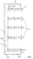
- Each module comprises, with reference to FIG. 1, a bottom panel 2, at least one lateral upright 1A, an upper distribution box 20, and shelves made up of an upper shelf 3a, of at least one intermediate shelf 3b , and a lower shelf 3c.
- Each lateral upright 1A consists of a generally L-shaped element comprising a vertical upright 100A and a base 110A (forming the leg of the L).
- the base 110A is covered with an insulation sleeve 21.
- the furniture of the invention is associated with refrigeration means capable of generating a stream of forced refrigerated air in which bathe the foodstuffs arranged on the intermediate 3b and lower 3c shelves.
- the shelves are of the type described in French patent application No. 92 05 526, and include internal conduits capable of allowing the circulation of refrigerated air.
- the upper shelf 3a comprises a single duct capable of directing an air curtain at its free end and directed downwards.
- the intermediate shelves 3b each comprise two internal ducts, a first duct intended to bring the refrigerated air at the end of said shelf downwards (in the direction of the foodstuffs arranged nearby), and a second duct suitable for conveying air taken up by the same shelf at its free end and coming from the area just above said shelf.
- the internal ducts or channels intended for the supply of fresh refrigerated air are called conduits or channels for supplying or blowing, while the channels or conduits intended for taking in the air having circulated between the shelves and on the foodstuffs, are called return channels or conduits.
- the shelves supply ducts have perforations on the lower panel, intended to bring the refrigerated air to the products.
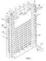
- each module comprises a panel 2 associated with two lateral uprights 1A and 1B arranged on either side of the panel 2.
- the bottom panel 2 has a generally parallelepiped shape and has a rear face and a face front parallel.
- the sides of the panel 2 have a return bearing the reference 200 and forming a shoulder of complementary shape to the lateral upright 1A so that the latter can be accommodated in the corresponding shoulder.
- Each lateral upright, and in particular the vertical upright 100A preferably has a rectangle cross section.
- the panel 2 and the respective lateral uprights 1A and 1B are secured to each other by means of holes or slots bearing the reference 4 disposed on the shoulder 201 on the sides of the panel, and in each of which is capable of being accommodated a hook 4a provided on the corresponding face of the lateral upright associated with 1A or 1B. More specifically, the hooks are provided on the lateral uprights, on the faces transverse to the plane of the panel 2. There is thus provided a succession of hooks 4a and holes 4 regularly spaced, respectively on the upright and the panel.
- the dimensions of the panel are of the order of: height 220 cm; width 100 cm; thickness 14 cm.
- the amounts for example have a cross section of 12 x 4 cm, for a height of the vertical amount 100A of 230 cm while the length of the base 110A is of the order of 90 cm.
- the panel 2 is produced from two sheet metal plates, a first solid sheet metal plate conforming to the rear face, while a second sheet metal plate forms the front face.
- the front face is provided with a series of orifices, preferably of generally rectangular shape.
- the sides of the panel 2 forming the returns 201 are produced for example by stamping the sheet forming the perforated front face.
- the front face of the panel 2 thus comprises two series of orifices.
- the first series of orifices consists of four orifices 13a, 14a, 15a and 16a, of generally rectangular shape and of dimension 18 x 8 cm, and arranged in the upper part of said front face.
- the second series of orifices comprises four parallel columns of orifices of generally elongated rectangular shape (in a direction parallel to the ground) and of dimension 18 x 4 cm.
- the orifices of the second series carry the references, for each column, respectively 7, 8, 7 'and 8'.
- the second series of orifices therefore forms a sort of matrix of orifices with columns and lines; in the example shown, the second series of orifices has four columns and twelve rows. It should be noted that the four orifices of the first series are arranged so that each orifice corresponds to a column of the second series of orifices.
- the orifice 13a corresponds to the column of the orifices 8 '
- the orifice 14a corresponds to the column of the orifices 7'
- the orifice 15a corresponds to the column of the orifices 8
- the orifice 16a corresponds to the column of the orifices 7.
- the orifices of the first series are not arranged in alignment on the same line. More particularly, starting from one side of the panel, the first and third holes 13a and 15a are arranged on the same line, while the second and fourth holes 14a and 16a are arranged on another line, offset downward relative to to the line formed by the orifices 13a and 15a. The offset is about 10 cm, for example.
- the panel 2 is formed so as to have internal channels or conduits capable of allowing the circulation of air inside the panel. More particularly, the respective orifices of the first series are connected by a conduit (not visible in FIG. 2) to the orifices of the corresponding column. Thus, for example, the orifice 13a is connected to the orifices 8 '.
- the internal conduits or channels arranged in the panel 2 are produced using stamped sheet metal of rectangular section and corresponding to the orifices in which it opens respectively.
- the interior space of the panel 2, between the internal conduits or channels is filled with an insulating material, such as a foam of synthetic material, which is injected inside the panel 2.
- Figure 4 shows the inner conduits or channels of the panel 2 and bearing the respective references 5, 6, 5 'and 6'. There is also a technical conduit provided with the reference 9 and intended for the passage of electrical wires for example.
- the vertical uprights 100A and 100B are also provided with holes 23a and 30a arranged on the face parallel to the front and rear faces of the panel 2.
- the holes 23a are for example three in number and arranged in the upper part of the upright, and in particular substantially at same level in height as the upper orifices 13a, 14a, 15a and 16a.
- the other holes 30a are regularly spaced and preferably arranged substantially opposite each of the lines of orifices of the second series, 7, 8, 7 'and 8'.
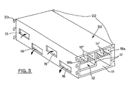
- the holes 23a are suitable for receiving hooks 23 provided on the upper intake and return air box, bearing the reference 20 and shown in FIG. 3.
- the box 20 has a parallelepiped shape whose dimension, in the direction parallel to panel 2, is substantially equal to the width of panel 2.
- the box 20 is preferably made from a folded and stamped sheet defining an interior space or wall, advantageously covered with insulating material (reference 17).
- internal panels are provided along the longitudinal direction of the box (parallel to the panel 2) and defining internal air circulation channels, namely supply ducts 11 ′ in the upper part of the box , and return ducts 12 '.
- the supply conduits 11 ' are separated from a supply channel 11 by a perforated plate 18a, while the return conduits 12' are separated from a return channel 12 by perforated sheets 18b.
- the rear face of the box 20, intended to bear against the front face of the panel 2, is provided with orifices, four in number and bearing the references 13, 14, 15 and 16.
- the orifices 13 to 16 are of shapes and dimensions complementary to the orifices 13a, 14a, 15a and 16a of the first series of orifices provided on the panel 2.
- the holes 13 to 16 provided on the rear face of the box 20 are arranged exactly opposite the holes 13a to 16a provided on the front face of the panel 2.
- arrows show the direction air circulation relative to the orifices 13 to 16 provided on the rear face of the box 20.
- the orifices 13 and 15, intended for the air intake are connected to the intake channel 12, while the orifices 14 and 16, intended for the supply of air, are connected to the supply channel 11 arranged in the lower part with respect to the return channel 12.
- the upper face of the latter is removably mounted.
- FIGS. 5A and 5B show in perspective from different angles an intermediate shelf 3b.
- intermediate shelf means a shelf on which are likely to be arranged food.
- an intermediate shelf 3b differs from the upper 3a and lower 3c shelves by the fact that the intermediate shelves each have two ducts, one intended for the supply of air and the other for the return of air.
- An intermediate shelf 3b is constituted for example from two stamped sheets forming three sections delimiting between them a first upper duct intended for the return of air, arranged in the upper part, and a second duct arranged in part lower and intended for the air supply. Each of the conduits opens at the free end of the shelf.
- the intermediate shelf 3b also has a rear face provided with four orifices bearing the references 8'a, 7'a, 8a and 7a, of shape, size and arrangement complementary to the orifices 8 ', 7', 8 and 7, respectively of the front face of the panel 2.
- the intermediate shelf 3b also includes two vertical side plates referenced 31 and 32 and provided at their rear end, on the side of the panel 2, with at least two hooks 30 capable of cooperating with the holes 30a provided on the vertical uprights 100A and 100B.
- the upper 3a and lower 3c shelves are of similar construction, except that the upper 3a and lower 3c shelves have only one supply and return channel respectively, and consequently only has on their rear face two orifices, namely orifices 7'a and 7a for the upper shelf 3a and orifices 8'a and 8a for the lower shelf 3c.
- the shelves 3a, 3c also include hooks capable of cooperating with the holes 30a provided on the vertical uprights 100A and 100B.
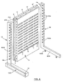
- the shelves shown in Figure 1 have their upper pan positioned perpendicular to the front face of the panel 2. According to another embodiment shown in Figure 10, the shelves are tilted forward to allow a better view of the products displayed for sale and facilitate their gripping.
- each vertical upright 100A for example, are capable of being fixed, on each side of said upright, two panels 2.
- each vertical upright 100A or 100B, parallel to the panel 2 are of such dimensions that they allow each to receive two hooks coming respectively from two neighboring boxes or from two adjacent shelves, that is to say arranged at the same level.
- a long linear assembly is thus produced by end-to-end assembly of several modules, as described above, and without great difficulty, since each element of each module has dimensions and a reduced weight and is therefore capable of be handled and transported by one person.
- the realization of each element forming a module is extremely simple to perform and economically.
- the modules assembled end to end to form a linear are then tightly connected to means for generating refrigerated air.
- the boxes, aligned and thus forming a single and same conduit and supply channel, and a single and same conduit and return channel, are joined end to end by means of seals known in themselves but not shown.
- the open faces of the end channels are connected to the air supply and return means. he is also provided tabs 22 on the boxes 20, in the front part to allow the attachment of a box to the neighboring box by bolting for example.
- the end upright 1C (see FIG. 9) has a transverse bar 120C (parallel to the base 110c) in the upper part.
- the amount 1C thus has the general shape of a U (and in which is likely to be accommodated a panel 19, preferably made of insulating material, and of complementary shape).
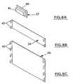
- FIGS. 8A , 8B and 8C The sealing means of FIG. 8A consists of a plug 27 comprising a front face 40 and a parallelepipedal rear face 41 of shape complementary to one of the orifices 7, 8, 7 'or 8'.
- the closing means consist alternatively of a rectangular plate of dimension and shape such that it can close eight orifices, on four columns and two lines.
- the plate 24 thus produced comprises hooks 42, at each end, and capable of being engaged in the holes 30a provided on the lateral uprights 100A and 100B.
- FIG. 8C there is shown a shutter panel of larger size and capable of shutting off a greater number of orifices on four columns and several lines.
- the panel 25 has hooks 43 on each of its sides, said hooks 43 being capable of cooperating with the holes 30a provided on the lateral uprights 100A and 100B.
- Said modules can also receive any type of known accessory (not shown), such as for example label holders, lighting tubes, night curtains.
Landscapes
- Physics & Mathematics (AREA)
- Thermal Sciences (AREA)
- Freezers Or Refrigerated Showcases (AREA)
Applications Claiming Priority (2)
| Application Number | Priority Date | Filing Date | Title |
|---|---|---|---|
| FR9211208 | 1992-09-21 | ||
| FR9211208A FR2695814B1 (fr) | 1992-09-21 | 1992-09-21 | Dispositif modulaire pour l'exposition à la vente de denrées alimentaires. |
Publications (1)
| Publication Number | Publication Date |
|---|---|
| EP0589783A1 true EP0589783A1 (de) | 1994-03-30 |
Family
ID=9433696
Family Applications (1)
| Application Number | Title | Priority Date | Filing Date |
|---|---|---|---|
| EP93402309A Withdrawn EP0589783A1 (de) | 1992-09-21 | 1993-09-21 | Modulare Vorrichtung zur Verkaufspresentation von Nahrung |
Country Status (2)
| Country | Link |
|---|---|
| EP (1) | EP0589783A1 (de) |
| FR (1) | FR2695814B1 (de) |
Cited By (19)
| Publication number | Priority date | Publication date | Assignee | Title |
|---|---|---|---|---|
| DE4332773A1 (de) * | 1993-09-25 | 1995-03-30 | Maentyoja Reijo | Kühlmöbel |
| WO2002005689A1 (en) * | 2000-06-26 | 2002-01-24 | Svein Henrik Vormedal | Shelved cupboard for refrigerated goods and method of controlled/regulated circulation of air in the shelved cupboard |
| EP1288597A1 (de) * | 2001-08-28 | 2003-03-05 | Bonnet Névé | Kühlmöbel |
| WO2004032688A1 (en) * | 2002-10-04 | 2004-04-22 | Carrier Commercial Refrigeration, Inc. | Merchandiser with horizontal air curtains |
| EP1460358A1 (de) * | 2001-12-27 | 2004-09-22 | Gac Corporation | Lagerungsvorrichtung |
| WO2006032934A1 (en) * | 2004-09-20 | 2006-03-30 | Enervac-Flutec Ltd | Air-curtain system for commercial open front refrigerators and display cabinets |
| WO2008074355A1 (en) | 2006-12-21 | 2008-06-26 | Carrier Corporation | Refrigerating cabinet |
| WO2009092604A2 (de) * | 2008-01-23 | 2009-07-30 | Girana Anuman-Rajadhon | Regal für ladenbau |
| WO2011121285A1 (en) * | 2010-03-29 | 2011-10-06 | Applied Design And Engineering Ltd. | Improvements in or relating to refrigerated display appliances |
| WO2011138704A1 (en) | 2010-05-03 | 2011-11-10 | Bim Birlesik Magazalar Anonim Sirketi | A display cabinet |
| WO2011121284A3 (en) * | 2010-03-29 | 2012-03-15 | Applied Design And Engineering Ltd | Improvements in or relating to refrigerated display appliances |
| WO2012142393A1 (en) * | 2011-04-15 | 2012-10-18 | Carrier Corporation | Shelve apparatus |
| US20140049014A1 (en) * | 2011-11-16 | 2014-02-20 | Helmut Schumacher | Hospital cart |
| WO2014181135A2 (en) * | 2013-05-10 | 2014-11-13 | Applied Design And Engineering Ltd | Improvements in or relating to refrigerated display appliances |
| NL2011668C2 (en) * | 2013-10-24 | 2015-04-29 | Fri Jado Bv | Modular merchandising display device. |
| CN105377086A (zh) * | 2013-05-13 | 2016-03-02 | 应用工程设计有限公司 | 冷藏展示装置的改进或与冷藏展示装置相关的改进 |
| GB2540021A (en) * | 2016-05-06 | 2017-01-04 | Vertical Cabinet Company Ltd | An open-front refrigerator and a method of cooling items therein |
| GB2549950A (en) * | 2016-05-03 | 2017-11-08 | The Marmon Group Ltd | Merchandise display system and unit |
| US10219638B2 (en) | 2013-05-10 | 2019-03-05 | Applied Design And Engineering Ltd. | Refrigerated display appliances |
Citations (4)
| Publication number | Priority date | Publication date | Assignee | Title |
|---|---|---|---|---|
| DE1235961B (de) * | 1958-04-02 | 1967-03-09 | Hussmann Refrigerator Co | Kuehlvitrine |
| US3392543A (en) * | 1967-07-17 | 1968-07-16 | Clark Equipment Co | Separable-section refrigerated case |
| FR2081020A1 (de) * | 1970-02-20 | 1971-11-26 | Linde Ag | |
| EP0442397A2 (de) * | 1990-02-13 | 1991-08-21 | Linde Aktiengesellschaft | Verkaufskühlmöbel |
-
1992
- 1992-09-21 FR FR9211208A patent/FR2695814B1/fr not_active Expired - Fee Related
-
1993
- 1993-09-21 EP EP93402309A patent/EP0589783A1/de not_active Withdrawn
Patent Citations (4)
| Publication number | Priority date | Publication date | Assignee | Title |
|---|---|---|---|---|
| DE1235961B (de) * | 1958-04-02 | 1967-03-09 | Hussmann Refrigerator Co | Kuehlvitrine |
| US3392543A (en) * | 1967-07-17 | 1968-07-16 | Clark Equipment Co | Separable-section refrigerated case |
| FR2081020A1 (de) * | 1970-02-20 | 1971-11-26 | Linde Ag | |
| EP0442397A2 (de) * | 1990-02-13 | 1991-08-21 | Linde Aktiengesellschaft | Verkaufskühlmöbel |
Cited By (38)
| Publication number | Priority date | Publication date | Assignee | Title |
|---|---|---|---|---|
| DE4332773A1 (de) * | 1993-09-25 | 1995-03-30 | Maentyoja Reijo | Kühlmöbel |
| US6742344B2 (en) | 2000-06-26 | 2004-06-01 | Svein Henrik Vormedal | Shelved cupboard for refrigerated goods and method of controlled/regulated circulation of air in the shelved cupboard |
| WO2002005689A1 (en) * | 2000-06-26 | 2002-01-24 | Svein Henrik Vormedal | Shelved cupboard for refrigerated goods and method of controlled/regulated circulation of air in the shelved cupboard |
| EP1288597A1 (de) * | 2001-08-28 | 2003-03-05 | Bonnet Névé | Kühlmöbel |
| FR2829230A1 (fr) * | 2001-08-28 | 2003-03-07 | Bonnet Neve | Meuble frigorifique, notamment un meuble vertical |
| EP1460358A1 (de) * | 2001-12-27 | 2004-09-22 | Gac Corporation | Lagerungsvorrichtung |
| EP1460358A4 (de) * | 2001-12-27 | 2006-11-08 | Gac Corp | Lagerungsvorrichtung |
| WO2004032688A1 (en) * | 2002-10-04 | 2004-04-22 | Carrier Commercial Refrigeration, Inc. | Merchandiser with horizontal air curtains |
| WO2006032934A1 (en) * | 2004-09-20 | 2006-03-30 | Enervac-Flutec Ltd | Air-curtain system for commercial open front refrigerators and display cabinets |
| WO2008074355A1 (en) | 2006-12-21 | 2008-06-26 | Carrier Corporation | Refrigerating cabinet |
| DE102008005736B4 (de) * | 2008-01-23 | 2012-07-19 | Girana Anuman-Rajadhon | Regal für Ladenbau |
| WO2009092604A2 (de) * | 2008-01-23 | 2009-07-30 | Girana Anuman-Rajadhon | Regal für ladenbau |
| WO2009092604A3 (de) * | 2008-01-23 | 2009-10-15 | Girana Anuman-Rajadhon | Regal für ladenbau |
| AU2009207799B2 (en) * | 2008-01-23 | 2014-04-10 | Girana Anuman-Rajadhon | Shelf for shop fitting |
| CN102843934A (zh) * | 2010-03-29 | 2012-12-26 | 应用工程设计有限公司 | 冷藏展示设备或与之相关的改进 |
| WO2011121284A3 (en) * | 2010-03-29 | 2012-03-15 | Applied Design And Engineering Ltd | Improvements in or relating to refrigerated display appliances |
| AU2011234247A1 (en) * | 2010-03-29 | 2012-11-01 | Applied Design And Engineering Ltd | Improvements in or relating to refrigerated display appliances |
| WO2011121285A1 (en) * | 2010-03-29 | 2011-10-06 | Applied Design And Engineering Ltd. | Improvements in or relating to refrigerated display appliances |
| US9775448B2 (en) | 2010-03-29 | 2017-10-03 | Applied Design And Engineering Ltd. | Refrigerated display appliances |
| AU2011234247B2 (en) * | 2010-03-29 | 2016-06-30 | Applied Design And Engineering Ltd | Improvements in or relating to refrigerated display appliances |
| CN102843934B (zh) * | 2010-03-29 | 2016-03-30 | 应用工程设计有限公司 | 冷藏展示单元 |
| US9265359B2 (en) | 2010-03-29 | 2016-02-23 | Applied Design And Engineering Ltd. | Refrigerated display appliances |
| WO2011138704A1 (en) | 2010-05-03 | 2011-11-10 | Bim Birlesik Magazalar Anonim Sirketi | A display cabinet |
| WO2012142393A1 (en) * | 2011-04-15 | 2012-10-18 | Carrier Corporation | Shelve apparatus |
| US20140049014A1 (en) * | 2011-11-16 | 2014-02-20 | Helmut Schumacher | Hospital cart |
| US10219638B2 (en) | 2013-05-10 | 2019-03-05 | Applied Design And Engineering Ltd. | Refrigerated display appliances |
| US9788666B2 (en) | 2013-05-10 | 2017-10-17 | Applied Design And Engineering Ltd. | Refrigerated display appliances |
| JP2016518934A (ja) * | 2013-05-10 | 2016-06-30 | アプライド デザイン アンド エンジニアリング リミテッドApplied Design And Engineering Ltd | 冷蔵陳列機器における改良または冷蔵陳列機器に関する改良 |
| WO2014181135A3 (en) * | 2013-05-10 | 2015-02-26 | Applied Design And Engineering Ltd | Improvements in or relating to refrigerated display appliances |
| RU2667870C2 (ru) * | 2013-05-10 | 2018-09-24 | Эплайд Дизайн Энд Энджениринг Лтд | Полка с воздуховодом для прилавка-витрины с открытой передней частью (варианты) |
| AU2014264449B2 (en) * | 2013-05-10 | 2018-05-31 | Applied Design And Engineering Ltd | Improvements in or relating to refrigerated display appliances |
| WO2014181135A2 (en) * | 2013-05-10 | 2014-11-13 | Applied Design And Engineering Ltd | Improvements in or relating to refrigerated display appliances |
| CN105377086A (zh) * | 2013-05-13 | 2016-03-02 | 应用工程设计有限公司 | 冷藏展示装置的改进或与冷藏展示装置相关的改进 |
| NL2011668C2 (en) * | 2013-10-24 | 2015-04-29 | Fri Jado Bv | Modular merchandising display device. |
| GB2549950A (en) * | 2016-05-03 | 2017-11-08 | The Marmon Group Ltd | Merchandise display system and unit |
| GB2540021B (en) * | 2016-05-06 | 2017-08-02 | Vertical Cabinet Company Ltd | An open-front refrigerator and a method of cooling items therein |
| GB2540021A (en) * | 2016-05-06 | 2017-01-04 | Vertical Cabinet Company Ltd | An open-front refrigerator and a method of cooling items therein |
| US11272794B2 (en) | 2016-05-06 | 2022-03-15 | Vertical Cabinet Company Ltd. | Open-front refrigerator and a method of cooling items therein |
Also Published As
| Publication number | Publication date |
|---|---|
| FR2695814A1 (fr) | 1994-03-25 |
| FR2695814B1 (fr) | 1994-12-09 |
Similar Documents
| Publication | Publication Date | Title |
|---|---|---|
| EP0589783A1 (de) | Modulare Vorrichtung zur Verkaufspresentation von Nahrung | |
| EP0639948B1 (de) | Zerlegbare gekühlte möbeln | |
| EP0516568B1 (de) | Wärmeisolierender Konditionierer für den gekühlten oder erwärmten Transport von Behältern mit Nahrungsmitteln | |
| FR3076546A1 (fr) | Systeme d'entreposage et distribution de marchandises | |
| EP2718625A1 (de) | Leuchtglastrennwand | |
| EP0113610B1 (de) | Gekühltes Ausstellungsmöbel | |
| WO2017118814A1 (fr) | Module de culture végétale avec plenum central pour mur végétalisé | |
| FR2701095A1 (fr) | Réfrigérateur modulaire. | |
| EP0720955B1 (de) | Verpackungs- und Präsentations-Behälter, insbesondere für Fahrräder | |
| FR2474852A1 (fr) | Appareil de stockage et de distribution de plats contenant des aliments et plateau adapte | |
| FR2955762A1 (fr) | Appareil de cuisson a infrarouge | |
| EP0801912A2 (de) | Modulares Schaugestell | |
| WO2019020788A1 (fr) | Abri stationnaire transportable, pour le stockage de modules de stockage d'énergie électrique | |
| CA2318370C (fr) | Tablette pour le support d'articles, en particulier dans des installations refrigerees | |
| FR2627215A1 (fr) | Kiosque modulaire notamment pour la vente ou l'exposition | |
| EP1945077B1 (de) | Wagen zur ausgabe von tabletts | |
| FR2735669A1 (fr) | Structure modulaire pour l'amenagement d'une surface, notamment d'une etagere ou d'un tiroir | |
| FR3066368B1 (fr) | Procede et dispositif de production de fumee et de refrigeration | |
| FR2745108A1 (fr) | Dispositif signaletique pour tablette | |
| FR2483169A1 (fr) | Conditionnement demontable pour l'elevage de plants ou de grains | |
| CH688221A5 (fr) | Dispositif de rangement et de stockage de récipients. | |
| FR2874162A1 (fr) | Presentoir pour produits destines a la vente | |
| FR2590143A1 (fr) | Dispositif de presentation a etiquetage amovible | |
| FR2820014A1 (fr) | Installation a au moins deux meubles pouvant etre accoles l'un a l'autre pour la presentation, notamment a la vente, de divers objets ou articles | |
| FR2637642A1 (fr) | Dispositif pour le positionnement de cloisons et, notamment, de cloisons de stands pour exposition temporaire |
Legal Events
| Date | Code | Title | Description |
|---|---|---|---|
| PUAI | Public reference made under article 153(3) epc to a published international application that has entered the european phase |
Free format text: ORIGINAL CODE: 0009012 |
|
| AK | Designated contracting states |
Kind code of ref document: A1 Designated state(s): AT BE CH DE DK ES GB GR IE IT LI LU MC NL PT SE |
|
| 17P | Request for examination filed |
Effective date: 19940214 |
|
| 17Q | First examination report despatched |
Effective date: 19950131 |
|
| GRAG | Despatch of communication of intention to grant |
Free format text: ORIGINAL CODE: EPIDOS AGRA |
|
| GRAG | Despatch of communication of intention to grant |
Free format text: ORIGINAL CODE: EPIDOS AGRA |
|
| GRAH | Despatch of communication of intention to grant a patent |
Free format text: ORIGINAL CODE: EPIDOS IGRA |
|
| STAA | Information on the status of an ep patent application or granted ep patent |
Free format text: STATUS: THE APPLICATION IS DEEMED TO BE WITHDRAWN |
|
| 18D | Application deemed to be withdrawn |
Effective date: 19980908 |