EP0589783A1 - Modular device for the sales presentation of foodstuffs - Google Patents
Modular device for the sales presentation of foodstuffs Download PDFInfo
- Publication number
- EP0589783A1 EP0589783A1 EP93402309A EP93402309A EP0589783A1 EP 0589783 A1 EP0589783 A1 EP 0589783A1 EP 93402309 A EP93402309 A EP 93402309A EP 93402309 A EP93402309 A EP 93402309A EP 0589783 A1 EP0589783 A1 EP 0589783A1
- Authority
- EP
- European Patent Office
- Prior art keywords
- panel
- module
- shelves
- orifices
- shelf
- Prior art date
- Legal status (The legal status is an assumption and is not a legal conclusion. Google has not performed a legal analysis and makes no representation as to the accuracy of the status listed.)
- Withdrawn
Links
Images


Classifications
-
- A—HUMAN NECESSITIES
- A47—FURNITURE; DOMESTIC ARTICLES OR APPLIANCES; COFFEE MILLS; SPICE MILLS; SUCTION CLEANERS IN GENERAL
- A47F—SPECIAL FURNITURE, FITTINGS, OR ACCESSORIES FOR SHOPS, STOREHOUSES, BARS, RESTAURANTS OR THE LIKE; PAYING COUNTERS
- A47F3/00—Show cases or show cabinets
- A47F3/04—Show cases or show cabinets air-conditioned, refrigerated
- A47F3/0439—Cases or cabinets of the open type
- A47F3/0443—Cases or cabinets of the open type with forced air circulation
- A47F2003/046—Cases or cabinets of the open type with forced air circulation with shelves having air ducts
Definitions
- the present invention relates to a device for the exposure to the sale of foodstuffs and associated with refrigeration means capable of creating and maintaining a circulation of refrigerated air in which the foodstuffs bathe. More particularly, the invention relates to the production of modular sets of refrigerated furniture for the presentation for sale of fresh foodstuffs.
- the refrigerated cabinets currently used are produced by end-to-end assembly of several modular elements, generally between 2.50 meters and 3.75 meters in length, in order to produce a presentation assembly of relatively great length.
- Each of these elements is itself made up of an autonomous piece of furniture and equipped for this purpose, by construction, with the means necessary for the refrigeration of the foodstuffs intended to be exposed, and in particular evaporators or exchangers, regulators, fans, thermostats, thermometers and any other known means of refrigeration.
- the latter are arranged in each of the so-called unitary pieces of furniture.
- Each unitary piece of furniture is manufactured so as to be autonomous and, at the point of sale, the unitary pieces of furniture are assembled one after the other end to end to form what is known as a "linear" presentation of food. refrigerated.
- Each unitary piece of furniture thus represents a bulk and a significant weight, since each piece of furniture is equipped with its own refrigeration means, and has a relatively large length in itself, as mentioned above (of the order of 2.50 meters to 4 meters). Consequently, the transport and handling of such elements represents a first difficulty and requires a significant workforce, of at least two to three people per piece of furniture. This results in very high transport and handling costs.
- the furniture should be assembled end to end to form the shelf for sale.
- This assembly aims on the one hand to mechanically fix the furniture to each other, and on the other hand to connect each piece of furniture to the various circuits necessary for the operation of the latter, such as refrigerant networks, electricity, waste water. This step also requires significant manpower, and is relatively long to perform.
- the present invention aims to remedy these drawbacks and proposes an assembly for the presentation for sale of refrigerated products, said assembly being produced from modular elements of reduced size, making it possible to substantially simplify the manufacture, transport, handling and assembly of such elements in order to produce a linear of great length, and this without sacrificing the overall cost of said linear, nor its reliability in terms of operation.
- the device comprises n modules arranged side by side, with n> 1, said n modules comprising n vertical bottom panels, and n + 1 vertical lateral uprights, plus means for detachably securing a module n to the neighboring module. n + 1.
- the device according to the invention comprises at least one of the characteristics described or claimed in patent applications No. 92 01 225 and 92 05 526, filed in the name of the applicant.
- the display cabinet for refrigerated foodstuffs consists of a plurality of unit modules assembled end to end to form an assembly of relatively long length, commonly called a "linear".
- Each module is made up, according to the invention, of several elements assembled together.
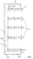
- Each module comprises, with reference to FIG. 1, a bottom panel 2, at least one lateral upright 1A, an upper distribution box 20, and shelves made up of an upper shelf 3a, of at least one intermediate shelf 3b , and a lower shelf 3c.
- Each lateral upright 1A consists of a generally L-shaped element comprising a vertical upright 100A and a base 110A (forming the leg of the L).
- the base 110A is covered with an insulation sleeve 21.
- the furniture of the invention is associated with refrigeration means capable of generating a stream of forced refrigerated air in which bathe the foodstuffs arranged on the intermediate 3b and lower 3c shelves.
- the shelves are of the type described in French patent application No. 92 05 526, and include internal conduits capable of allowing the circulation of refrigerated air.
- the upper shelf 3a comprises a single duct capable of directing an air curtain at its free end and directed downwards.
- the intermediate shelves 3b each comprise two internal ducts, a first duct intended to bring the refrigerated air at the end of said shelf downwards (in the direction of the foodstuffs arranged nearby), and a second duct suitable for conveying air taken up by the same shelf at its free end and coming from the area just above said shelf.
- the internal ducts or channels intended for the supply of fresh refrigerated air are called conduits or channels for supplying or blowing, while the channels or conduits intended for taking in the air having circulated between the shelves and on the foodstuffs, are called return channels or conduits.
- the shelves supply ducts have perforations on the lower panel, intended to bring the refrigerated air to the products.
- each module comprises a panel 2 associated with two lateral uprights 1A and 1B arranged on either side of the panel 2.
- the bottom panel 2 has a generally parallelepiped shape and has a rear face and a face front parallel.
- the sides of the panel 2 have a return bearing the reference 200 and forming a shoulder of complementary shape to the lateral upright 1A so that the latter can be accommodated in the corresponding shoulder.
- Each lateral upright, and in particular the vertical upright 100A preferably has a rectangle cross section.
- the panel 2 and the respective lateral uprights 1A and 1B are secured to each other by means of holes or slots bearing the reference 4 disposed on the shoulder 201 on the sides of the panel, and in each of which is capable of being accommodated a hook 4a provided on the corresponding face of the lateral upright associated with 1A or 1B. More specifically, the hooks are provided on the lateral uprights, on the faces transverse to the plane of the panel 2. There is thus provided a succession of hooks 4a and holes 4 regularly spaced, respectively on the upright and the panel.
- the dimensions of the panel are of the order of: height 220 cm; width 100 cm; thickness 14 cm.
- the amounts for example have a cross section of 12 x 4 cm, for a height of the vertical amount 100A of 230 cm while the length of the base 110A is of the order of 90 cm.
- the panel 2 is produced from two sheet metal plates, a first solid sheet metal plate conforming to the rear face, while a second sheet metal plate forms the front face.
- the front face is provided with a series of orifices, preferably of generally rectangular shape.
- the sides of the panel 2 forming the returns 201 are produced for example by stamping the sheet forming the perforated front face.
- the front face of the panel 2 thus comprises two series of orifices.
- the first series of orifices consists of four orifices 13a, 14a, 15a and 16a, of generally rectangular shape and of dimension 18 x 8 cm, and arranged in the upper part of said front face.
- the second series of orifices comprises four parallel columns of orifices of generally elongated rectangular shape (in a direction parallel to the ground) and of dimension 18 x 4 cm.
- the orifices of the second series carry the references, for each column, respectively 7, 8, 7 'and 8'.
- the second series of orifices therefore forms a sort of matrix of orifices with columns and lines; in the example shown, the second series of orifices has four columns and twelve rows. It should be noted that the four orifices of the first series are arranged so that each orifice corresponds to a column of the second series of orifices.
- the orifice 13a corresponds to the column of the orifices 8 '
- the orifice 14a corresponds to the column of the orifices 7'
- the orifice 15a corresponds to the column of the orifices 8
- the orifice 16a corresponds to the column of the orifices 7.
- the orifices of the first series are not arranged in alignment on the same line. More particularly, starting from one side of the panel, the first and third holes 13a and 15a are arranged on the same line, while the second and fourth holes 14a and 16a are arranged on another line, offset downward relative to to the line formed by the orifices 13a and 15a. The offset is about 10 cm, for example.
- the panel 2 is formed so as to have internal channels or conduits capable of allowing the circulation of air inside the panel. More particularly, the respective orifices of the first series are connected by a conduit (not visible in FIG. 2) to the orifices of the corresponding column. Thus, for example, the orifice 13a is connected to the orifices 8 '.
- the internal conduits or channels arranged in the panel 2 are produced using stamped sheet metal of rectangular section and corresponding to the orifices in which it opens respectively.
- the interior space of the panel 2, between the internal conduits or channels is filled with an insulating material, such as a foam of synthetic material, which is injected inside the panel 2.
- Figure 4 shows the inner conduits or channels of the panel 2 and bearing the respective references 5, 6, 5 'and 6'. There is also a technical conduit provided with the reference 9 and intended for the passage of electrical wires for example.
- the vertical uprights 100A and 100B are also provided with holes 23a and 30a arranged on the face parallel to the front and rear faces of the panel 2.
- the holes 23a are for example three in number and arranged in the upper part of the upright, and in particular substantially at same level in height as the upper orifices 13a, 14a, 15a and 16a.
- the other holes 30a are regularly spaced and preferably arranged substantially opposite each of the lines of orifices of the second series, 7, 8, 7 'and 8'.
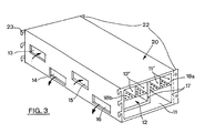
- the holes 23a are suitable for receiving hooks 23 provided on the upper intake and return air box, bearing the reference 20 and shown in FIG. 3.
- the box 20 has a parallelepiped shape whose dimension, in the direction parallel to panel 2, is substantially equal to the width of panel 2.
- the box 20 is preferably made from a folded and stamped sheet defining an interior space or wall, advantageously covered with insulating material (reference 17).
- internal panels are provided along the longitudinal direction of the box (parallel to the panel 2) and defining internal air circulation channels, namely supply ducts 11 ′ in the upper part of the box , and return ducts 12 '.
- the supply conduits 11 ' are separated from a supply channel 11 by a perforated plate 18a, while the return conduits 12' are separated from a return channel 12 by perforated sheets 18b.
- the rear face of the box 20, intended to bear against the front face of the panel 2, is provided with orifices, four in number and bearing the references 13, 14, 15 and 16.
- the orifices 13 to 16 are of shapes and dimensions complementary to the orifices 13a, 14a, 15a and 16a of the first series of orifices provided on the panel 2.
- the holes 13 to 16 provided on the rear face of the box 20 are arranged exactly opposite the holes 13a to 16a provided on the front face of the panel 2.
- arrows show the direction air circulation relative to the orifices 13 to 16 provided on the rear face of the box 20.
- the orifices 13 and 15, intended for the air intake are connected to the intake channel 12, while the orifices 14 and 16, intended for the supply of air, are connected to the supply channel 11 arranged in the lower part with respect to the return channel 12.
- the upper face of the latter is removably mounted.
- FIGS. 5A and 5B show in perspective from different angles an intermediate shelf 3b.
- intermediate shelf means a shelf on which are likely to be arranged food.
- an intermediate shelf 3b differs from the upper 3a and lower 3c shelves by the fact that the intermediate shelves each have two ducts, one intended for the supply of air and the other for the return of air.
- An intermediate shelf 3b is constituted for example from two stamped sheets forming three sections delimiting between them a first upper duct intended for the return of air, arranged in the upper part, and a second duct arranged in part lower and intended for the air supply. Each of the conduits opens at the free end of the shelf.
- the intermediate shelf 3b also has a rear face provided with four orifices bearing the references 8'a, 7'a, 8a and 7a, of shape, size and arrangement complementary to the orifices 8 ', 7', 8 and 7, respectively of the front face of the panel 2.
- the intermediate shelf 3b also includes two vertical side plates referenced 31 and 32 and provided at their rear end, on the side of the panel 2, with at least two hooks 30 capable of cooperating with the holes 30a provided on the vertical uprights 100A and 100B.
- the upper 3a and lower 3c shelves are of similar construction, except that the upper 3a and lower 3c shelves have only one supply and return channel respectively, and consequently only has on their rear face two orifices, namely orifices 7'a and 7a for the upper shelf 3a and orifices 8'a and 8a for the lower shelf 3c.
- the shelves 3a, 3c also include hooks capable of cooperating with the holes 30a provided on the vertical uprights 100A and 100B.
- the shelves shown in Figure 1 have their upper pan positioned perpendicular to the front face of the panel 2. According to another embodiment shown in Figure 10, the shelves are tilted forward to allow a better view of the products displayed for sale and facilitate their gripping.
- each vertical upright 100A for example, are capable of being fixed, on each side of said upright, two panels 2.
- each vertical upright 100A or 100B, parallel to the panel 2 are of such dimensions that they allow each to receive two hooks coming respectively from two neighboring boxes or from two adjacent shelves, that is to say arranged at the same level.
- a long linear assembly is thus produced by end-to-end assembly of several modules, as described above, and without great difficulty, since each element of each module has dimensions and a reduced weight and is therefore capable of be handled and transported by one person.
- the realization of each element forming a module is extremely simple to perform and economically.
- the modules assembled end to end to form a linear are then tightly connected to means for generating refrigerated air.
- the boxes, aligned and thus forming a single and same conduit and supply channel, and a single and same conduit and return channel, are joined end to end by means of seals known in themselves but not shown.
- the open faces of the end channels are connected to the air supply and return means. he is also provided tabs 22 on the boxes 20, in the front part to allow the attachment of a box to the neighboring box by bolting for example.
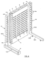
- the end upright 1C (see FIG. 9) has a transverse bar 120C (parallel to the base 110c) in the upper part.
- the amount 1C thus has the general shape of a U (and in which is likely to be accommodated a panel 19, preferably made of insulating material, and of complementary shape).
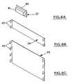
- FIGS. 8A , 8B and 8C The sealing means of FIG. 8A consists of a plug 27 comprising a front face 40 and a parallelepipedal rear face 41 of shape complementary to one of the orifices 7, 8, 7 'or 8'.
- the closing means consist alternatively of a rectangular plate of dimension and shape such that it can close eight orifices, on four columns and two lines.
- the plate 24 thus produced comprises hooks 42, at each end, and capable of being engaged in the holes 30a provided on the lateral uprights 100A and 100B.
- FIG. 8C there is shown a shutter panel of larger size and capable of shutting off a greater number of orifices on four columns and several lines.
- the panel 25 has hooks 43 on each of its sides, said hooks 43 being capable of cooperating with the holes 30a provided on the lateral uprights 100A and 100B.
- Said modules can also receive any type of known accessory (not shown), such as for example label holders, lighting tubes, night curtains.
Abstract
Description
La présente invention concerne un dispositif pour l'exposition à la vente de denrées alimentaires et associé à des moyens de réfrigération aptes à créer et maintenir une circulation d'air réfrigéré dans laquelle baignent les denrées. Plus particulièrement, l'invention concerne la réalisation d'ensembles modulaires de meubles réfrigérés pour la présentation à la vente de denrées alimentaires fraîches.The present invention relates to a device for the exposure to the sale of foodstuffs and associated with refrigeration means capable of creating and maintaining a circulation of refrigerated air in which the foodstuffs bathe. More particularly, the invention relates to the production of modular sets of refrigerated furniture for the presentation for sale of fresh foodstuffs.
Les meubles réfrigérés actuellement utilisés sont réalisés par assemblage bout à bout de plusieurs éléments modulaires, de longueur généralement comprise entre 2,50 mètres et 3,75 mètres, afin de réaliser un ensemble de présentation de relativement grande longueur. Chacun de ces éléments est lui-même constitué d'un meuble autonome et équipé à cette fin, par construction, des moyens nécessaires à la réfrigération des denrées destinées à être exposées, et notamment des évaporateurs ou échangeurs, détendeurs, ventilateurs, thermostats, thermomètres et tout autre moyen connu de réfrigération. Ces derniers sont disposés dans chacun des meubles dits unitaires. Chaque meuble unitaire est fabriqué de manière a être autonome et, sur le lieu de vente, les meubles unitaires sont assemblés les uns aux autres bout à bout pour former ce qu'il est convenu d'appeler un "linéaire" de présentation d'aliments réfrigérés.The refrigerated cabinets currently used are produced by end-to-end assembly of several modular elements, generally between 2.50 meters and 3.75 meters in length, in order to produce a presentation assembly of relatively great length. Each of these elements is itself made up of an autonomous piece of furniture and equipped for this purpose, by construction, with the means necessary for the refrigeration of the foodstuffs intended to be exposed, and in particular evaporators or exchangers, regulators, fans, thermostats, thermometers and any other known means of refrigeration. The latter are arranged in each of the so-called unitary pieces of furniture. Each unitary piece of furniture is manufactured so as to be autonomous and, at the point of sale, the unitary pieces of furniture are assembled one after the other end to end to form what is known as a "linear" presentation of food. refrigerated.
Chaque meuble unitaire représente ainsi un encombrement et un poids important, puisque chaque meuble est équipé de ses propres moyens de réfrigération, et présente une longueur relativement importante en elle-même, comme mentionné ci-dessus (de l'ordre de 2,50 mètres à 4 mètres). En conséquence, le transport et la manutention de tels éléments représentent une première difficulté et nécessitent une main-d'oeuvre importante, d'au moins deux à trois personnes par meuble. Il en résulte des coûts de transport et de manutention très élevés.Each unitary piece of furniture thus represents a bulk and a significant weight, since each piece of furniture is equipped with its own refrigeration means, and has a relatively large length in itself, as mentioned above (of the order of 2.50 meters to 4 meters). Consequently, the transport and handling of such elements represents a first difficulty and requires a significant workforce, of at least two to three people per piece of furniture. This results in very high transport and handling costs.
Par ailleurs, une fois les meubles apportés et disposés sur le site de la vente, il convient d'assembler les meubles bout à bout pour former le linéaire d'exposition à la vente. Cet assemblage vise d'une part à fixer mécaniquement les meubles les uns aux autres, et d'autre part à raccorder chaque meuble aux différents circuits nécessaires au fonctionnement de ces derniers, tels que réseaux de liquide frigorigène, électricité, eaux usées. Cette étape nécessite également une main-d'oeuvre importante, et est relativement longue à effectuer.In addition, once the furniture has been brought in and placed on the sale site, the furniture should be assembled end to end to form the shelf for sale. This assembly aims on the one hand to mechanically fix the furniture to each other, and on the other hand to connect each piece of furniture to the various circuits necessary for the operation of the latter, such as refrigerant networks, electricity, waste water. This step also requires significant manpower, and is relatively long to perform.
En résumé, l'état actuel de la technique d'un tel ensemble pour la présentation d'aliments réfrigérés nécessite de faire appel à une structure de fabrication, des moyens de transport et de manutention, et des opérations d'assemblage, complexes, longues et onéreuses.In summary, the current state of the art of such an assembly for the presentation of refrigerated food requires the use of a manufacturing structure, means of transport and handling, and assembly operations, complex, long. and expensive.
On a tenté, sans succès, de réduire la taille et le poids de chaque meuble unitaire, afin de rendre leur fabrication et notamment leur transport et manutention moins difficile. De telles tentatives se sont heurtées à des difficultés techniques compte tenu de la présence et la disposition des moyens de réfrigération propres à chaque meuble et disposés dans ces derniers. En effet, les moyens de réfrigération font appel à des composants dont il est extrêmement difficile, voire impossible, de diminuer le nombre, l'encombrement et le poids. En outre, chaque meuble doit être soumis à des cycles de dégivrage des évaporateurs (ou des échangeurs) qui nécessitent des bacs de recueillement des eaux de dégivrage et de condensation. Lesdits bacs doivent être évidemment étanches et être raccordés de façon étanche également au réseau des eaux usées.Attempts have been made, without success, to reduce the size and the weight of each unitary piece of furniture, in order to make their manufacture and in particular their transport and handling less difficult. Such attempts have encountered technical difficulties given the presence and arrangement of the refrigeration means specific to each piece of furniture and arranged in the latter. Indeed, the refrigeration means use components which it is extremely difficult, if not impossible, to reduce the number, size and weight. In addition, each piece of furniture must be subject to defrost cycles of evaporators (or exchangers) which require tanks for collecting defrost and condensation water. Said tanks must obviously be watertight and must also be tightly connected to the wastewater network.
Enfin, la réduction de la longueur de chaque meuble nécessite de réduire également la longueur des évaporateurs (ou échangeurs) disposés dans chaque meuble. Or, ceci conduirait à en multiplier le nombre et en conséquence à augmenter considérablement le coût de tels meubles réfrigérés.Finally, reducing the length of each piece of furniture also requires reducing the length of the evaporators (or exchangers) arranged in each piece of furniture. However, this would lead to multiplying the number and consequently considerably increasing the cost of such refrigerated furniture.
La présente invention vise à remédier à ces inconvénients et propose un ensemble pour la présentation à la vente de denrées réfrigérées, ledit ensemble étant réalisé à partir d'éléments modulaires de taille réduite, permettant de simplifier de façon substantielle la fabrication, le transport, la manutention et l'assemblage de tels éléments en vue de réaliser un linéaire de grande longueur, et ce sans sacrifier au coût global dudit linéaire, ni à sa fiabilité sur le plan du fonctionnement.The present invention aims to remedy these drawbacks and proposes an assembly for the presentation for sale of refrigerated products, said assembly being produced from modular elements of reduced size, making it possible to substantially simplify the manufacture, transport, handling and assembly of such elements in order to produce a linear of great length, and this without sacrificing the overall cost of said linear, nor its reliability in terms of operation.
A cette fin, selon l'invention, le dispositif pour l'exposition à la vente de denrées alimentaires, associé à des moyens de réfrigération aptes à créer et maintenir une circulation d'air réfrigéré dans laquelle baignent les denrées, du type comprenant au moins un module comportant un panneau de fond et des étagères pourvues de conduits internes destinés à ladite circulation, est caractérisé en ce que chaque module comprend les éléments suivants :
- un panneau de fond vertical ;
- au moins un montant latéral vertical ;
- au moins une étagère ; et
- des moyens de solidarisation amovible d'au moins un des éléments avec les deux autres.
- a vertical bottom panel;
- at least one vertical lateral upright;
- at least one shelf; and
- means for removably securing at least one of the elements with the other two.
De préférence, le dispositif comporte n modules disposés côte à côte, avec n > 1, lesdits n modules comprenant n panneaux de fonds verticaux, et n+1 montants latéraux verticaux, plus des moyens de solidarisation amovible d'un module n au module voisin n+1.Preferably, the device comprises n modules arranged side by side, with n> 1, said n modules comprising n vertical bottom panels, and n + 1 vertical lateral uprights, plus means for detachably securing a module n to the neighboring module. n + 1.
Avantageusement, le dispositif selon l'invention comporte l'une au moins des caractéristiques décrites ou revendiquées dans les demandes de brevet n° 92 01 225 et 92 05 526, déposées au nom de la demanderesse.Advantageously, the device according to the invention comprises at least one of the characteristics described or claimed in patent applications No. 92 01 225 and 92 05 526, filed in the name of the applicant.
L'invention sera bien comprise à la lumière des dessins annexés, dans lesquels :
- la figure 1 est une vue de côté schématique d'un module unitaire assemblé ;
- la figure 2 est une vue en perspective éclatée d'un module et montrant le panneau de fond et les deux montants latéraux, verticaux ;
- la figure 3 montre en perspective le caisson de distribution associé à un module ;
- la figure 4 montre en perspective éclatée le panneau et les deux montants de la figure 2 en vue partielle tronquée selon la ligne IV-IV, de la figure 2 ;
- les figures 5A et 5B montrent une étagère intermédiaire respectivement en perspective de face et en perspective arrière ;
- les figures 6A et 6B montrent une étagère supérieure respectivement en vue perspective arrière et de côté ;
- les figures 7A et 7B montrent une étagère inférieure respectivement en vue perspective arrière et de côté ;
- les figures 8A, 8B et 8C montrent en perspective des variantes respectives des moyens d'obturation des orifices de passage d'air réfrigéré du panneau, non opérationnels ;
- la figure 9 montre une vue similaire à la figure 2, pour un module disposé à l'extrémité de la succession de modules constituant le linéaire ;
- la figure 10 montre une variante avec étagères inclinées ; et
- la figure 11 montre une variante pourvue d'éléments de décoration et éléments porteurs d'informations.
- Figure 1 is a schematic side view of an assembled unit module;
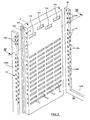
- Figure 2 is an exploded perspective view of a module and showing the bottom panel and the two side uprights, vertical;
- Figure 3 shows in perspective the distribution box associated with a module;
- Figure 4 shows an exploded perspective view of the panel and the two uprights of Figure 2 in partial truncated view along the line IV-IV, of Figure 2;
- FIGS. 5A and 5B show an intermediate shelf respectively in front perspective and in rear perspective;
- FIGS. 6A and 6B show an upper shelf respectively in rear and side perspective view;
- FIGS. 7A and 7B show a lower shelf respectively in rear and side perspective view;
- FIGS. 8A, 8B and 8C show in perspective respective variants of the means for closing the orifices for the passage of refrigerated air of the panel, which are not operational;
- FIG. 9 shows a view similar to FIG. 2, for a module arranged at the end of the succession of modules constituting the linear;
- Figure 10 shows a variant with inclined shelves; and
- FIG. 11 shows a variant provided with decorative elements and elements carrying information.
Le meuble de présentation de denrées alimentaires réfrigérées, selon l'invention, est constitué d'une pluralité de modules unitaires assemblés bout à bout pour former un ensemble d'une relativement grande longueur, appelé communément un "linéaire".The display cabinet for refrigerated foodstuffs, according to the invention, consists of a plurality of unit modules assembled end to end to form an assembly of relatively long length, commonly called a "linear".
Chaque module est constitué, selon l'invention, de plusieurs éléments assemblés les uns aux autres. Chaque module comprend, en référence à la figure 1, un panneau de fond 2, au moins un montant latéral 1A , un caisson supérieur de distribution 20 , et des étagères constituées d'une étagère supérieure 3a, d'au moins une étagère intermédiaire 3b, et d'une étagère inférieure 3c.Each module is made up, according to the invention, of several elements assembled together. Each module comprises, with reference to FIG. 1, a
Chaque montant latéral 1A est constitué d'un élément en forme générale de L comprenant un montant vertical 100A et une base 110A (formant la jambe du L). La base 110A est recouverte d'un manchon d'isolation 21 .Each
Le meuble de l'invention est associé à des moyens de réfrigération aptes à engendrer un courant d'air forcé réfrigéré dans lequel baignent les denrées alimentaires disposées sur les étagères intermédiaire 3b et inférieure 3c. De préférence, les étagères sont du type de celles décrites dans la demande de brevet français n° 92 05 526, et comprennent des conduits internes aptes à permettre la circulation de l'air réfrigéré. Plus particulièrement, l'étagère supérieure 3a comprend un conduit unique apte à diriger un rideau d'air à son extrémité libre et dirigé vers le bas. Les étagères intermédiaires 3b comprennent chacune deux conduits internes, un premier conduit destiné à amener l'air réfrigéré à l'extrémité de ladite étagère vers le bas (en direction des denrées disposées à proximité), et un second conduit apte à véhiculer l'air repris par la même étagère à son extrémité libre et provenant de la zone située juste au dessus de ladite étagère. Les conduits internes ou canaux destinés à l'amenée d'air réfrigéré frais sont appelés conduits ou canaux d'amenée ou de soufflage, tandis que les canaux ou conduits destinés à reprendre l'air ayant circulé entre les étagères et sur les denrées, sont appelés canaux ou conduits de reprise. Les conduits d'amenée des étagères comportent des perforations sur le pan inférieur, destinées à amener l'air réfrigéré sur les produits.The furniture of the invention is associated with refrigeration means capable of generating a stream of forced refrigerated air in which bathe the foodstuffs arranged on the intermediate 3b and lower 3c shelves. Preferably, the shelves are of the type described in French patent application No. 92 05 526, and include internal conduits capable of allowing the circulation of refrigerated air. More particularly, the
En référence à la figure 2, chaque module comporte un panneau 2 associé à deux montants latéraux 1A et 1B disposés de part et d'autre du panneau 2. Le panneau de fond 2 présente une forme générale parallélépipédique et comporte une face arrière et une face avant parallèles. Les côtés du panneau 2 comportent un retour portant la référence 200 et formant un épaulement de forme complémentaire au montant latéral 1A de manière à ce que ce dernier puisse venir se loger dans l'épaulement correspondant. Chaque montant latéral, et notamment le montant vertical 100A, présente de préférence une section droite rectangle.With reference to FIG. 2, each module comprises a
Le panneau 2 et les montants latéraux respectifs 1A et 1B sont solidarisés entre-eux par l'intermédiaire de trous ou fentes portant la référence 4 disposés sur l'épaulement 201 des côtés du panneau, et dans chacun desquels est susceptible de venir se loger un crochet 4a prévu sur la face correspondante du montant latéral associé à 1A ou 1B. Plus précisément, les crochets sont prévus sur les montants latéraux, sur les faces transversales au plan du panneau 2 . Il est ainsi prévu une succession de crochets 4a et trous 4 régulièrement espacés, respectivement sur le montant et le panneau.The
A titre indicatif, les dimensions du panneau sont de l'ordre de : hauteur 220 cm ; largeur 100 cm ; épaisseur 14 cm. Les montants par exemple présentent une section droite de 12 x 4 cm, pour une hauteur du montant vertical 100A de 230 cm tandis que la longueur de la base 110A est de l'ordre de 90 cm.As an indication, the dimensions of the panel are of the order of: height 220 cm; width 100 cm;
Selon une forme préférée de réalisation, le panneau 2 est réalisé à partir de deux plaques de tôle, une première plaque de tôle pleine conformant la face arrière, tandis qu'une seconde plaque de tôle forme la face avant. La face avant est pourvue d'une série d'orifices, de forme générale rectangulaire de préférence. Les côtés du panneau 2 formant les retours 201, sont réalisés par exemple par emboutissage de la tôle formant la face frontale perforée. La face avant du panneau 2 comporte ainsi deux séries d'orifices. La première série d'orifices est constituée de quatre orifices 13a, 14a, 15a et 16a , de forme générale rectangulaire et de dimension 18 x 8 cm, et disposés en partie supérieure de ladite face frontale. La deuxième série d'orifices comporte quatre colonnes parallèles d'orifices de forme générale rectangulaire allongée (suivant une direction parallèle au sol) et de dimension 18 x 4 cm. Les orifices de la seconde série portent les références, pour chaque colonne, respectivement 7, 8, 7' et 8'. La seconde série d'orifices forme donc une sorte de matrice d'orifices avec colonnes et lignes ; dans l'exemple représenté, la seconde série d'orifices comporte quatre colonnes et douze lignes. Il est à noter que les quatre orifices de la première série sont disposés de manière que chaque orifice correspond à une colonne de la seconde série d'orifices. Ainsi, l'orifice 13a correspond à la colonne des orifices 8', l'orifice 14a correspond à la colonne des orifices 7', l'orifice 15a correspond à la colonne des orifices 8 et l'orifice 16a correspond à la colonne des orifices 7. Les orifices de la première série ne sont pas disposés en alignement sur une même ligne. Plus particulièrement, en partant d'un côté du panneau, les premier et troisième orifices 13a et 15a sont disposés sur la même ligne, tandis que les second et quatrième orifices 14a et 16a sont disposés sur une autre ligne, décalée vers le bas par rapport à la ligne formée par les orifices 13a et 15a. Le décalage est d'environ 10 cm, par exemple.According to a preferred embodiment, the
Le panneau 2 est constitué de manière à présenter des canaux ou conduits internes aptes à permettre la circulation d'air à l'intérieur du panneau. Plus particulièrement les orifices respectifs de la première série sont reliés par un conduit (non visible sur la figure 2) aux orifices de la colonne correspondante. Ainsi par exemple l'orifice 13a est relié aux orifices 8'. Selon un mode illustratif de réalisation, les conduits ou canaux internes disposés dans le panneau 2 sont réalisés à l'aide de tôle emboutie de section rectangulaire et correspondant aux orifices dans laquelle elle débouche respectivement. De préférence, l'espace intérieur du panneau 2, entre les conduits ou canaux internes, est rempli d'un matériau isolant, telle qu'une mousse en matériau synthétique, qui est injecté à l'intérieur du panneau 2.The
La figure 4 montre les conduits ou canaux intérieurs du panneau 2 et portant les références respectives 5, 6, 5' et 6'. Il est prévu également un conduit technique portant la référence 9 et destiné au passage de fils électriques par exemple.Figure 4 shows the inner conduits or channels of the
Les montants verticaux 100A et 100B sont pourvus également de trous 23a et 30a disposés sur la face parallèle aux faces avant et arrière du panneau 2. Les trous 23a sont au nombre par exemple de trois et disposés en partie supérieure du montant, et notamment sensiblement au même niveau en hauteur que les orifices supérieurs 13a, 14a, 15a et 16a. Les autres trous 30a sont régulièrement espacés et disposés de préférence sensiblement en regard de chacune des lignes d'orifices de la seconde série, 7, 8, 7' et 8'. Les trous 23a sont aptes à recevoir des crochets 23 prévus sur le caisson supérieur d'amenée et de reprise d'air, portant la référence 20 et montré sur la figure 3. Le caisson 20 présente une forme parallélépipédique dont la dimension, dans la direction parallèle au panneau 2, est sensiblement égale à la largeur du panneau 2. Le caisson 20 est de préférence constitué à partir d'une tôle pliée et emboutie définissant un espace intérieur ou paroi, recouvert avantageusement de matière isolante (référence 17). A l'intérieur du caisson 20, sont prévus des panneaux internes suivant la direction longitudinale du caisson (parallèle au panneau 2) et définissant des canaux internes de circulation d'air, à savoir des conduits d'amenée 11' en partie supérieure du caisson, et des conduits de reprise 12'. Les conduits d'amenée 11' sont séparés d'un canal d'amenée 11 par une tôle perforée 18a, tandis que les conduits de reprise 12' sont séparés d'un canal de reprise 12 par des tôles perforées 18b. La face arrière du caisson 20, destinée à porter contre la face frontale du panneau 2, est pourvue d'orifices, au nombre de quatre et portant les références 13, 14, 15 et 16. Les orifices 13 à 16 sont de formes et dimensions complémentaires aux orifices 13a, 14a, 15a et 16a de la première série d'orifices prévus sur le panneau 2. Lorsque le caisson 20 est fixé sur les montants latéraux 1A et 1B, par les crochets 23 et les trous 23a, les orifices 13 à 16 prévus sur la face arrière du caisson 20 sont disposés exactement en regard des orifices 13a à 16a prévus sur la face frontale du panneau 2. Sur la figure 3, des flèches montrent le sens de circulation d'air par rapport aux orifices 13 à 16 prévus sur la face arrière du caisson 20. En l'espèce, les orifices 13 et 15, destinés à la reprise d'air, sont reliés au canal de reprise 12, tandis que les orifices 14 et 16, destinés à l'amenée d'air, sont reliés au canal d'amenée 11 disposé en partie inférieure par rapport au canal de reprise 12.The
Afin de permettre le nettoyage des canaux et conduits internes disposés dans le caisson 20, la face supérieure de ce dernier est montée amovible.In order to allow the cleaning of the internal channels and conduits arranged in the
Les figures 5 et 6 montrent plus particulièrement les étagères susceptibles d'être montées et fixées sur l'ensemble formé par le panneau et les deux montants solidarisés. Les figures 5A et 5B montrent en perspective sous des angles différents une étagère intermédiaire 3b. On entend par étagère intermédiaire une étagère sur laquelle sont susceptibles d'être disposées des denrées. Egalement, une étagère intermédiaire 3b se distingue des étagères supérieure 3a et inférieure 3c par le fait que les étagères intermédiaires comportent chacune deux conduits, l'un destiné à l'amenée d'air et l'autre à la reprise d'air. Une étagère intermédiaire 3b est constituée par exemple à partir de deux tôles embouties formant trois pans délimitant entre eux un premier conduit supérieur destiné à la reprise de l'air, disposé en partie supérieure, et un second conduit disposé en partie inférieure et destiné à l'amenée d'air. Chacun des conduits débouche à l'extrémité libre de l'étagère. L'étagère intermédiaire 3b comporte également une face arrière pourvue de quatre orifices portant les références 8'a, 7'a, 8a et 7a, de forme, dimension et disposition complémentaires aux orifices 8', 7', 8 et 7, respectivement de la face frontale du panneau 2. L'étagère intermédiaire 3b comporte également deux plaques latérales verticales référencées 31 et 32 et pourvues à leur extrémité arrière, du côté du panneau 2, d'au moins deux crochets 30 susceptibles de coopérer avec les trous 30a prévus sur les montants verticaux 100A et 100B.Figures 5 and 6 show more particularly the shelves capable of being mounted and fixed on the assembly formed by the panel and the two uprights secured. FIGS. 5A and 5B show in perspective from different angles an
De même, les étagères supérieure 3a et inférieure 3c sont de construction similaire, excepté que les étagères supérieure 3a et inférieure 3c ne comportent qu'un seul canal respectivement d'amenée et de reprise, et en conséquence ne comporte sur leur face arrière que deux orifices, à savoir orifices 7'a et 7a pour l'étagère supérieure 3a et les orifices 8'a et 8a pour l'étagère inférieure 3c.Likewise, the upper 3a and lower 3c shelves are of similar construction, except that the upper 3a and lower 3c shelves have only one supply and return channel respectively, and consequently only has on their rear face two orifices, namely orifices 7'a and 7a for the
Les étagères 3a, 3c comportent également des crochets susceptibles de coopérer avec les trous 30a prévus sur les montants verticaux 100A et 100B.The
Les étagères représentées à la figure 1 ont leur pan supérieur positionné perpendiculairement à la face avant du panneau 2. Selon une autre forme de réalisation présentée à la figure 10, les étagères sont inclinées vers l'avant pour permettre une meilleure vue sur les produits exposés à la vente et faciliter leur préhension.The shelves shown in Figure 1 have their upper pan positioned perpendicular to the front face of the
Une fois le panneau 2 solidarisé sur les montants verticaux 100A et 100B, le caisson 20 solidarisé sur les montants latéraux, et les étagères de même solidarisées sur les montants latéraux, on obtient un module unitaire auquel est susceptible d'être fixé un autre module. Un module est fixé au module voisin par l'intermédiaire de crochets 4a prévus sur les montants latéraux 100A et 100B, sur la face des montants transversale au plan des panneaux et opposée à ce dernier. Ainsi, à chaque montant vertical 100A, par exemple, sont susceptibles d'être fixés, de chaque côté dudit montant, deux panneaux 2. De même, il est à noter que les trous 23a et 30a prévus sur la face de chaque montant vertical 100A ou 100B, parallèle au panneau 2, sont de dimensions telles qu'ils permettent de recevoir chacun deux crochets provenant respectivement de deux caissons voisins ou de deux étagères voisines, c'est-à-dire disposés au même niveau.Once the
On réalise ainsi un ensemble linéaire de grande longueur par assemblage bout à bout de plusieurs modules, tel que décrit ci-dessus, et ce sans grandes difficultés, puisque chaque élément de chaque module présente des dimensions et un poids réduit et est donc susceptible d'être manipulé et transporté par une seule personne. En outre, la réalisation de chaque- élément formant un module est extrêmement simple à réaliser et de manière économique.A long linear assembly is thus produced by end-to-end assembly of several modules, as described above, and without great difficulty, since each element of each module has dimensions and a reduced weight and is therefore capable of be handled and transported by one person. In addition, the realization of each element forming a module is extremely simple to perform and economically.
Les modules assemblés bout à bout pour former un linéaire sont ensuite reliés de manière étanche à des moyens de génération d'air réfrigéré.The modules assembled end to end to form a linear are then tightly connected to means for generating refrigerated air.
A cet effet, plus particulièrement, les caissons, alignés et formant ainsi un seul et même conduit et canal d'amenée, et un seul et même conduit et canal de reprise, sont joints bout à bout par l'intermédiaire de joints d'étanchéité connus en eux mêmes mais non représentés.For this purpose, more particularly, the boxes, aligned and thus forming a single and same conduit and supply channel, and a single and same conduit and return channel, are joined end to end by means of seals known in themselves but not shown.
Par ailleurs, les faces ouvertes des canaux d'extrémité sont reliées aux moyens d'amenée et de reprise d'air. Il est prévu également des pattes 22 sur les caissons 20, en partie frontale pour permettre la fixation d'un caisson au caisson voisin par boulonnage par exemple.Furthermore, the open faces of the end channels are connected to the air supply and return means. he is also provided
En extrémité du linéaire formé par l'assemblage de modules bout à bout, il est prévu d'obturer la face latérale pour délimiter un ensemble de réfrigération. A cet effet, le montant d'extrémité 1C (voir figure 9) comporte en partie supérieure une barre transversale 120C (parallèle à la base 110c). Le montant 1C présente ainsi la forme générale d'un U (et dans lequel est susceptible de venir se loger un panneau 19, de préférence en matériau isolant, et de forme complémentaire).At the end of the shelf formed by the assembly of end-to-end modules, provision is made for closing the side face to delimit a refrigeration assembly. For this purpose, the end upright 1C (see FIG. 9) has a transverse bar 120C (parallel to the base 110c) in the upper part. The
Afin d'éviter les pertes de charge et fuites dues aux orifices libres du panneau 2, il est prévu d'obturer les orifices qui ne sont pas associés à des étagères, par des moyens d'obturation dont trois variantes seront représentées respectivement aux figures 8A, 8B et 8C. Le moyen d'obturation de la figure 8A est constitué d'un bouchon 27 comportant une face avant 40 et une face arrière parallélépipédique 41 de forme complémentaire à l'un des orifices 7, 8, 7' ou 8'. Sur la figure 8B les moyens d'obturation sont constitués en variante d'une plaque rectangulaire de dimension et forme telles qu'elle puisse obturer huit orifices, sur quatre colonnes et deux lignes. La plaque 24 ainsi réalisée comporte des crochets 42, à chaque extrémité, et susceptibles d'être engagés dans les trous 30a prévus sur les montants latéraux 100A et 100B. Sur la figure 8C, est représenté un panneau d'obturation de dimension plus importante et susceptible d'obturer un plus grand nombre d'orifices sur quatre colonnes et plusieurs lignes. De même, le panneau 25 comporte des crochets 43 sur chacun de ses côtés, lesdits crochets 43 étant susceptibles de coopérer avec les trous 30a prévus sur les montants latéraux 100A et 100B.In order to avoid pressure losses and leaks due to the free orifices of the
Les formes précédemment décrites de réalisation de l'invention permettent, de plus, d'associer lesdits modules (voir figure 11), soit à des éléments porteurs d'informations ou de messages, tels que par exemple la désignation des produits 51, soit à un élément décoratif, tel qu'un fronton, disposé en partie haute 50 ou un bandeau disposé en partie basse 52, soit encore à un élément de protection tel qu'un pare-choc 53.The previously described embodiments of the invention also make it possible to associate said modules (see FIG. 11), either with elements carrying information or messages, such as for example the designation of the
Lesdits modules peuvent également recevoir tout type d'accessoire connu (non représenté), tel que par exemple portes-étiquettes, tubes d'éclairage, rideaux de nuit.Said modules can also receive any type of known accessory (not shown), such as for example label holders, lighting tubes, night curtains.
Claims (20)
caractérisé en ce qu'il comporte n modules côte à côte (n=au moins 2), soit au total n panneaux de fond et n+1 montants verticaux, et en ce qu'il comporte en outre des moyens de solidarisation amovible d'un module (n) au module voisin (n + 1). 2 - Device according to claim 1,
characterized in that it comprises n modules side by side (n = at least 2), that is to say in total n bottom panels and n + 1 vertical uprights, and in that it also comprises removable means of securing a module (n) to the neighboring module (n + 1).
caractérisé en ce que lesdits moyens de solidarisation d'un module à l'autre comprennent des moyens de solidarisation amovible entre le panneau du module n et le montant du module voisin n+1. 3 - Device according to claim 2,
characterized in that the said means for securing from one module to the other comprise removable securing means between the panel of the module n and the upright of the neighboring module n + 1.
caractérisé en ce que chaque module comprend un élément d'amenée et de reprise d'air réfrigéré, relié aux dits moyens de réfrigération et aux dits conduits internes dudit panneau. 4 - Device according to one of the preceding claims,
characterized in that each module comprises a supply and return element for refrigerated air, connected to said refrigeration means and to said internal conduits of said panel.
caractérisé en ce que ledit élément d'amenée et de reprise d'air est constitué d'un caisson creux, de forme générale allongée, et pourvu de cloisons internes disposées sensiblement parallèlement à la direction longitudinale des étagères. 5 - Device according to claim 4,
characterized in that said air intake and return element consists of a hollow box, of generally elongated shape, and provided with internal partitions arranged substantially parallel to the longitudinal direction of the shelves.
caractérisé en ce que chaque caisson est apte à être raccordé au caisson du module voisin, de façon étanche. 6 - Device according to claims 2 and 5,
characterized in that each box is able to be connected to the box of the neighboring module, in a sealed manner.
caractérisé en ce que le panneau de fond comprend des bords latéraux verticaux de forme complémentaire au dit montant. 7 - Device according to one of the preceding claims,
characterized in that the bottom panel comprises vertical lateral edges of shape complementary to the said upright.
caractérisé en ce que chaque montant présente une section droite de forme rectangulaire ou carrée, et est réalisé à partir d'une tôle pliée et emboutie. 8 - Device according to one of the preceding claims,
characterized in that each upright has a cross section of rectangular or square shape, and is made from a folded and stamped sheet.
caractérisé en ce que ledit panneau de fond comprend deux parois parallèles, constituant respectivement la face avant et la face arrière, la face avant étant apte à mettre en communication les conduits internes disposés dans le panneau et les conduits internes prévus dans lesdites étagères. 9 - Device according to one of the preceding claims,
characterized in that said bottom panel comprises two parallel walls, respectively constituting the front face and the rear face, the front face being able to put in communication the internal conduits arranged in the panel and the internal conduits provided in said shelves.
caractérisé en ce que le panneau de fond est constitué de deux plaques de tôle métallique parallèles dans lesquelles sont disposés des conduits internes sensiblement verticaux, ladite face avant étant pourvue d'ajourages, et l'espace entre les conduits et les faces avant et arrière étant rempli de matériau présentant des propriétés d'isolation thermique. 10 - Device according to claim 9,
characterized in that the bottom panel consists of two parallel metal sheet plates in which are disposed substantially vertical internal conduits, said front face being provided with openings, and the space between the conduits and the front and rear faces being filled with material having thermal insulation properties.
caractérisé en ce qu'il comporte des moyens de solidarisation amovible constitués de crochets disposés sur l'un des éléments, et susceptibles de coopérer avec des lumières correspondantes sur l'autre élément. 11 - Device according to one of the preceding claims,
characterized in that it comprises removable securing means consisting of hooks arranged on one of the elements, and capable of cooperating with corresponding lights on the other element.
caractérisé en ce que les crochets sont disposés sur les montants et les lumières sur ledit panneau, tandis que des crochets sont disposés sur les étagères et des lumières correspondantes sur lesdits montants. 12 - Device according to claim 11,
characterized in that the hooks are arranged on the uprights and the lights on said panel, while hooks are arranged on the shelves and corresponding lights on said uprights.
caractérisé en ce que les lumières prévues sur les montants sont de largeur telle qu'elles permettent de recevoir deux crochets côte à côte appartenant respectivement à deux étagères voisines, à savoir une étagère du module n et une étagère du module voisin n+1. 13 - Device according to claim 12,
characterized in that the slots provided on the uprights are of such width that they allow two hooks to be side by side belonging respectively to two neighboring shelves, namely a shelf of module n and a shelf of neighboring module n + 1.
caractérisé en ce que ledit panneau de fond est pourvu d'au moins un passage destiné à une câblerie électrique. 14 - Device according to one of the preceding claims,
characterized in that said bottom panel is provided with at least one passage intended for electrical wiring.
caractérisé en ce que ledit caisson est susceptible de porter par une de ses faces contre ledit panneau, ladite face comportant des ouvertures aptes à mettre en communication d'une part les conduits internes du panneau, d'autre part les conduits internes dudit caisson. 15 - Device according to claims 5 and 10,
characterized in that said box is capable of bearing by one of its faces against said panel, said face comprising openings capable of placing on the one hand the internal conduits of the panel, on the other hand the internal conduits of said box.
caractérisé en ce qu'il comporte également des organes d'obturation des orifices du panneau, non opérationnels (c'est-à-dire les orifices non disposés en regard des étagères et/ou du caisson). 16 - Device according to claim 10,
characterized in that it also comprises members for closing the orifices of the panel, which are not operational (that is to say the orifices not arranged facing the shelves and / or the box).
caractérisé en ce que lesdits organes d'obturation sont constitués de bouchons individuels pour chaque orifice. 17 - Device according to claim 16,
characterized in that said closure members consist of individual plugs for each orifice.
caractérisé en ce que lesdits organes d'obturation sont constitués de plaques susceptibles d'être fixées sur lesdits panneaux de façon amovible et aptes à obturer plusieurs orifices de la face avant dudit panneau. 18 - Device according to claim 16,
characterized in that said shutter members consist of plates capable of being fixed on said panels in a removable manner and capable of closing several orifices on the front face of said panel.
caractérisé en ce qu'il comprend plusieurs étagères présentant avec le fond un angle différent de 90°. 19 - Device according to one of the preceding claims,
characterized in that it comprises several shelves having with the bottom an angle different from 90 °.
caractérisé en ce qu'il comporte en outre des éléments décoratifs, tels que bandeau, pare-choc, fronton et/ou des éléments porteurs d'informations relatives aux produits. 20 - Device according to one of the preceding claims,
characterized in that it further comprises decorative elements, such as strip, bumper, pediment and / or elements carrying information relating to the products.
Applications Claiming Priority (2)
| Application Number | Priority Date | Filing Date | Title |
|---|---|---|---|
| FR9211208 | 1992-09-21 | ||
| FR9211208A FR2695814B1 (en) | 1992-09-21 | 1992-09-21 | Modular device for the exposure to the sale of foodstuffs. |
Publications (1)
| Publication Number | Publication Date |
|---|---|
| EP0589783A1 true EP0589783A1 (en) | 1994-03-30 |
Family
ID=9433696
Family Applications (1)
| Application Number | Title | Priority Date | Filing Date |
|---|---|---|---|
| EP93402309A Withdrawn EP0589783A1 (en) | 1992-09-21 | 1993-09-21 | Modular device for the sales presentation of foodstuffs |
Country Status (2)
| Country | Link |
|---|---|
| EP (1) | EP0589783A1 (en) |
| FR (1) | FR2695814B1 (en) |
Cited By (19)
| Publication number | Priority date | Publication date | Assignee | Title |
|---|---|---|---|---|
| DE4332773A1 (en) * | 1993-09-25 | 1995-03-30 | Maentyoja Reijo | Piece of refrigerated furniture |
| WO2002005689A1 (en) * | 2000-06-26 | 2002-01-24 | Svein Henrik Vormedal | Shelved cupboard for refrigerated goods and method of controlled/regulated circulation of air in the shelved cupboard |
| EP1288597A1 (en) * | 2001-08-28 | 2003-03-05 | Bonnet Névé | Refrigerated cabinet |
| WO2004032688A1 (en) * | 2002-10-04 | 2004-04-22 | Carrier Commercial Refrigeration, Inc. | Merchandiser with horizontal air curtains |
| EP1460358A1 (en) * | 2001-12-27 | 2004-09-22 | Gac Corporation | Storage device |
| WO2006032934A1 (en) * | 2004-09-20 | 2006-03-30 | Enervac-Flutec Ltd | Air-curtain system for commercial open front refrigerators and display cabinets |
| WO2008074355A1 (en) | 2006-12-21 | 2008-06-26 | Carrier Corporation | Refrigerating cabinet |
| WO2009092604A2 (en) * | 2008-01-23 | 2009-07-30 | Girana Anuman-Rajadhon | Shelf for shop fitting |
| WO2011121285A1 (en) * | 2010-03-29 | 2011-10-06 | Applied Design And Engineering Ltd. | Improvements in or relating to refrigerated display appliances |
| WO2011138704A1 (en) | 2010-05-03 | 2011-11-10 | Bim Birlesik Magazalar Anonim Sirketi | A display cabinet |
| WO2011121284A3 (en) * | 2010-03-29 | 2012-03-15 | Applied Design And Engineering Ltd | Improvements in or relating to refrigerated display appliances |
| WO2012142393A1 (en) * | 2011-04-15 | 2012-10-18 | Carrier Corporation | Shelve apparatus |
| US20140049014A1 (en) * | 2011-11-16 | 2014-02-20 | Helmut Schumacher | Hospital cart |
| WO2014181135A2 (en) * | 2013-05-10 | 2014-11-13 | Applied Design And Engineering Ltd | Improvements in or relating to refrigerated display appliances |
| NL2011668C2 (en) * | 2013-10-24 | 2015-04-29 | Fri Jado Bv | Modular merchandising display device. |
| CN105377086A (en) * | 2013-05-13 | 2016-03-02 | 应用工程设计有限公司 | Improvements in or relating to refrigerated display appliances |
| GB2540021A (en) * | 2016-05-06 | 2017-01-04 | Vertical Cabinet Company Ltd | An open-front refrigerator and a method of cooling items therein |
| GB2549950A (en) * | 2016-05-03 | 2017-11-08 | The Marmon Group Ltd | Merchandise display system and unit |
| US10219638B2 (en) | 2013-05-10 | 2019-03-05 | Applied Design And Engineering Ltd. | Refrigerated display appliances |
Citations (4)
| Publication number | Priority date | Publication date | Assignee | Title |
|---|---|---|---|---|
| DE1235961B (en) * | 1958-04-02 | 1967-03-09 | Hussmann Refrigerator Co | Cool showcase |
| US3392543A (en) * | 1967-07-17 | 1968-07-16 | Clark Equipment Co | Separable-section refrigerated case |
| FR2081020A1 (en) * | 1970-02-20 | 1971-11-26 | Linde Ag | |
| EP0442397A2 (en) * | 1990-02-13 | 1991-08-21 | Linde Aktiengesellschaft | Refrigerated vending cabinet |
-
1992
- 1992-09-21 FR FR9211208A patent/FR2695814B1/en not_active Expired - Fee Related
-
1993
- 1993-09-21 EP EP93402309A patent/EP0589783A1/en not_active Withdrawn
Patent Citations (4)
| Publication number | Priority date | Publication date | Assignee | Title |
|---|---|---|---|---|
| DE1235961B (en) * | 1958-04-02 | 1967-03-09 | Hussmann Refrigerator Co | Cool showcase |
| US3392543A (en) * | 1967-07-17 | 1968-07-16 | Clark Equipment Co | Separable-section refrigerated case |
| FR2081020A1 (en) * | 1970-02-20 | 1971-11-26 | Linde Ag | |
| EP0442397A2 (en) * | 1990-02-13 | 1991-08-21 | Linde Aktiengesellschaft | Refrigerated vending cabinet |
Cited By (38)
| Publication number | Priority date | Publication date | Assignee | Title |
|---|---|---|---|---|
| DE4332773A1 (en) * | 1993-09-25 | 1995-03-30 | Maentyoja Reijo | Piece of refrigerated furniture |
| US6742344B2 (en) | 2000-06-26 | 2004-06-01 | Svein Henrik Vormedal | Shelved cupboard for refrigerated goods and method of controlled/regulated circulation of air in the shelved cupboard |
| WO2002005689A1 (en) * | 2000-06-26 | 2002-01-24 | Svein Henrik Vormedal | Shelved cupboard for refrigerated goods and method of controlled/regulated circulation of air in the shelved cupboard |
| EP1288597A1 (en) * | 2001-08-28 | 2003-03-05 | Bonnet Névé | Refrigerated cabinet |
| FR2829230A1 (en) * | 2001-08-28 | 2003-03-07 | Bonnet Neve | REFRIGERATED FURNITURE, ESPECIALLY A VERTICAL FURNITURE |
| EP1460358A1 (en) * | 2001-12-27 | 2004-09-22 | Gac Corporation | Storage device |
| EP1460358A4 (en) * | 2001-12-27 | 2006-11-08 | Gac Corp | Storage device |
| WO2004032688A1 (en) * | 2002-10-04 | 2004-04-22 | Carrier Commercial Refrigeration, Inc. | Merchandiser with horizontal air curtains |
| WO2006032934A1 (en) * | 2004-09-20 | 2006-03-30 | Enervac-Flutec Ltd | Air-curtain system for commercial open front refrigerators and display cabinets |
| WO2008074355A1 (en) | 2006-12-21 | 2008-06-26 | Carrier Corporation | Refrigerating cabinet |
| DE102008005736B4 (en) * | 2008-01-23 | 2012-07-19 | Girana Anuman-Rajadhon | Shelf for shop fitting |
| WO2009092604A2 (en) * | 2008-01-23 | 2009-07-30 | Girana Anuman-Rajadhon | Shelf for shop fitting |
| WO2009092604A3 (en) * | 2008-01-23 | 2009-10-15 | Girana Anuman-Rajadhon | Shelf for shop fitting |
| AU2009207799B2 (en) * | 2008-01-23 | 2014-04-10 | Girana Anuman-Rajadhon | Shelf for shop fitting |
| CN102843934A (en) * | 2010-03-29 | 2012-12-26 | 应用工程设计有限公司 | Improvements in or relating to refrigerated display appliances |
| WO2011121284A3 (en) * | 2010-03-29 | 2012-03-15 | Applied Design And Engineering Ltd | Improvements in or relating to refrigerated display appliances |
| AU2011234247A1 (en) * | 2010-03-29 | 2012-11-01 | Applied Design And Engineering Ltd | Improvements in or relating to refrigerated display appliances |
| WO2011121285A1 (en) * | 2010-03-29 | 2011-10-06 | Applied Design And Engineering Ltd. | Improvements in or relating to refrigerated display appliances |
| US9775448B2 (en) | 2010-03-29 | 2017-10-03 | Applied Design And Engineering Ltd. | Refrigerated display appliances |
| AU2011234247B2 (en) * | 2010-03-29 | 2016-06-30 | Applied Design And Engineering Ltd | Improvements in or relating to refrigerated display appliances |
| CN102843934B (en) * | 2010-03-29 | 2016-03-30 | 应用工程设计有限公司 | Refrigerated display units |
| US9265359B2 (en) | 2010-03-29 | 2016-02-23 | Applied Design And Engineering Ltd. | Refrigerated display appliances |
| WO2011138704A1 (en) | 2010-05-03 | 2011-11-10 | Bim Birlesik Magazalar Anonim Sirketi | A display cabinet |
| WO2012142393A1 (en) * | 2011-04-15 | 2012-10-18 | Carrier Corporation | Shelve apparatus |
| US20140049014A1 (en) * | 2011-11-16 | 2014-02-20 | Helmut Schumacher | Hospital cart |
| US10219638B2 (en) | 2013-05-10 | 2019-03-05 | Applied Design And Engineering Ltd. | Refrigerated display appliances |
| US9788666B2 (en) | 2013-05-10 | 2017-10-17 | Applied Design And Engineering Ltd. | Refrigerated display appliances |
| JP2016518934A (en) * | 2013-05-10 | 2016-06-30 | アプライド デザイン アンド エンジニアリング リミテッドApplied Design And Engineering Ltd | Improvements in refrigerated display equipment or improvements in refrigerated display equipment |
| WO2014181135A3 (en) * | 2013-05-10 | 2015-02-26 | Applied Design And Engineering Ltd | Improvements in or relating to refrigerated display appliances |
| RU2667870C2 (en) * | 2013-05-10 | 2018-09-24 | Эплайд Дизайн Энд Энджениринг Лтд | Shelf with air duct for display cabinet with open front part (options) |
| AU2014264449B2 (en) * | 2013-05-10 | 2018-05-31 | Applied Design And Engineering Ltd | Improvements in or relating to refrigerated display appliances |
| WO2014181135A2 (en) * | 2013-05-10 | 2014-11-13 | Applied Design And Engineering Ltd | Improvements in or relating to refrigerated display appliances |
| CN105377086A (en) * | 2013-05-13 | 2016-03-02 | 应用工程设计有限公司 | Improvements in or relating to refrigerated display appliances |
| NL2011668C2 (en) * | 2013-10-24 | 2015-04-29 | Fri Jado Bv | Modular merchandising display device. |
| GB2549950A (en) * | 2016-05-03 | 2017-11-08 | The Marmon Group Ltd | Merchandise display system and unit |
| GB2540021B (en) * | 2016-05-06 | 2017-08-02 | Vertical Cabinet Company Ltd | An open-front refrigerator and a method of cooling items therein |
| GB2540021A (en) * | 2016-05-06 | 2017-01-04 | Vertical Cabinet Company Ltd | An open-front refrigerator and a method of cooling items therein |
| US11272794B2 (en) | 2016-05-06 | 2022-03-15 | Vertical Cabinet Company Ltd. | Open-front refrigerator and a method of cooling items therein |
Also Published As
| Publication number | Publication date |
|---|---|
| FR2695814B1 (en) | 1994-12-09 |
| FR2695814A1 (en) | 1994-03-25 |
Similar Documents
| Publication | Publication Date | Title |
|---|---|---|
| EP0589783A1 (en) | Modular device for the sales presentation of foodstuffs | |
| EP0639948B1 (en) | Collapsible refrigerated cabinets | |
| FR2893166A1 (en) | DISTRIBUTOR OF FOOD PRODUCTS, IN PARTICULAR BEVERAGES. | |
| CA1266847A (en) | Anti-theft vending case | |
| FR3076546A1 (en) | STORAGE SYSTEM AND DISTRIBUTION OF GOODS | |
| EP0113610B1 (en) | Refrigerated display cabinet | |
| EP2718625A1 (en) | Illuminating glass partition | |
| WO2017118814A1 (en) | Plant culture module with central plenum for green wall | |
| FR2701095A1 (en) | Modular refrigerator | |
| EP0720955B1 (en) | Packaging and display container, in particular for bicycles | |
| FR2955762A1 (en) | INFRARED COOKING APPARATUS | |
| EP0801912A2 (en) | Modular display case | |
| WO2019020788A1 (en) | Transportable stationary enclosure, for storing electrical energy storage modules | |
| CA2318370C (en) | Shelf for holding articles, especially in refrigeration units | |
| FR2627215A1 (en) | Polygonal modular kiosk - has central column and corner pillars fitted between floor and roof frame sections | |
| EP1945077B1 (en) | Meal tray dispensing trolley | |
| FR2909536A1 (en) | DISPLAY, PARTICULARLY ADAPTED FOR CONFECTIONERY PRODUCTS | |
| FR2735669A1 (en) | Modular walls for dividing shelf or drawer into compartments | |
| FR3066368B1 (en) | METHOD AND DEVICE FOR PRODUCING SMOKE AND REFRIGERATION | |
| FR2745108A1 (en) | Labelling system for goods on supermarket shelf | |
| CH688221A5 (en) | Modular storage unit for containers, especially bottles | |
| FR2874162A1 (en) | Display case for use in e.g. tobacconist`s shop, has vertical and parallel posts cooperating with removable intermediate locking and connection units and blocked with each other with gap between them using locking and connection units | |
| FR2590143A1 (en) | Display device with removable labelling | |
| FR2820014A1 (en) | Display system for use in tobacconist's comprises two or more units which fit together, hooks on one unit fitting into slots on other | |
| FR2537417A1 (en) | Refrigerated display unit |
Legal Events
| Date | Code | Title | Description |
|---|---|---|---|
| PUAI | Public reference made under article 153(3) epc to a published international application that has entered the european phase |
Free format text: ORIGINAL CODE: 0009012 |
|
| AK | Designated contracting states |
Kind code of ref document: A1 Designated state(s): AT BE CH DE DK ES GB GR IE IT LI LU MC NL PT SE |
|
| 17P | Request for examination filed |
Effective date: 19940214 |
|
| 17Q | First examination report despatched |
Effective date: 19950131 |
|
| GRAG | Despatch of communication of intention to grant |
Free format text: ORIGINAL CODE: EPIDOS AGRA |
|
| GRAG | Despatch of communication of intention to grant |
Free format text: ORIGINAL CODE: EPIDOS AGRA |
|
| GRAH | Despatch of communication of intention to grant a patent |
Free format text: ORIGINAL CODE: EPIDOS IGRA |
|
| STAA | Information on the status of an ep patent application or granted ep patent |
Free format text: STATUS: THE APPLICATION IS DEEMED TO BE WITHDRAWN |
|
| 18D | Application deemed to be withdrawn |
Effective date: 19980908 |