EP0588593A2 - Brennkraftmaschine mit Vorkammer - Google Patents
Brennkraftmaschine mit Vorkammer Download PDFInfo
- Publication number
- EP0588593A2 EP0588593A2 EP93307224A EP93307224A EP0588593A2 EP 0588593 A2 EP0588593 A2 EP 0588593A2 EP 93307224 A EP93307224 A EP 93307224A EP 93307224 A EP93307224 A EP 93307224A EP 0588593 A2 EP0588593 A2 EP 0588593A2
- Authority
- EP
- European Patent Office
- Prior art keywords
- chamber
- control valve
- engine
- fuel
- main
- Prior art date
- Legal status (The legal status is an assumption and is not a legal conclusion. Google has not performed a legal analysis and makes no representation as to the accuracy of the status listed.)
- Granted
Links
Images


Classifications
-
- F—MECHANICAL ENGINEERING; LIGHTING; HEATING; WEAPONS; BLASTING
- F02—COMBUSTION ENGINES; HOT-GAS OR COMBUSTION-PRODUCT ENGINE PLANTS
- F02B—INTERNAL-COMBUSTION PISTON ENGINES; COMBUSTION ENGINES IN GENERAL
- F02B19/00—Engines characterised by precombustion chambers
- F02B19/16—Chamber shapes or constructions not specific to sub-groups F02B19/02 - F02B19/10
- F02B19/165—The shape or construction of the pre-combustion chambers is specially adapted to be formed, at least in part, of ceramic material
-
- F—MECHANICAL ENGINEERING; LIGHTING; HEATING; WEAPONS; BLASTING
- F01—MACHINES OR ENGINES IN GENERAL; ENGINE PLANTS IN GENERAL; STEAM ENGINES
- F01L—CYCLICALLY OPERATING VALVES FOR MACHINES OR ENGINES
- F01L3/00—Lift-valve, i.e. cut-off apparatus with closure members having at least a component of their opening and closing motion perpendicular to the closing faces; Parts or accessories thereof
- F01L3/20—Shapes or constructions of valve members, not provided for in preceding subgroups of this group
-
- F—MECHANICAL ENGINEERING; LIGHTING; HEATING; WEAPONS; BLASTING
- F01—MACHINES OR ENGINES IN GENERAL; ENGINE PLANTS IN GENERAL; STEAM ENGINES
- F01L—CYCLICALLY OPERATING VALVES FOR MACHINES OR ENGINES
- F01L9/00—Valve-gear or valve arrangements actuated non-mechanically
- F01L9/20—Valve-gear or valve arrangements actuated non-mechanically by electric means
-
- F—MECHANICAL ENGINEERING; LIGHTING; HEATING; WEAPONS; BLASTING
- F02—COMBUSTION ENGINES; HOT-GAS OR COMBUSTION-PRODUCT ENGINE PLANTS
- F02B—INTERNAL-COMBUSTION PISTON ENGINES; COMBUSTION ENGINES IN GENERAL
- F02B19/00—Engines characterised by precombustion chambers
- F02B19/02—Engines characterised by precombustion chambers the chamber being periodically isolated from its cylinder
-
- F—MECHANICAL ENGINEERING; LIGHTING; HEATING; WEAPONS; BLASTING
- F02—COMBUSTION ENGINES; HOT-GAS OR COMBUSTION-PRODUCT ENGINE PLANTS
- F02D—CONTROLLING COMBUSTION ENGINES
- F02D19/00—Controlling engines characterised by their use of non-liquid fuels, pluralities of fuels, or non-fuel substances added to the combustible mixtures
- F02D19/02—Controlling engines characterised by their use of non-liquid fuels, pluralities of fuels, or non-fuel substances added to the combustible mixtures peculiar to engines working with gaseous fuels
- F02D19/021—Control of components of the fuel supply system
- F02D19/023—Control of components of the fuel supply system to adjust the fuel mass or volume flow
- F02D19/024—Control of components of the fuel supply system to adjust the fuel mass or volume flow by controlling fuel injectors
-
- F—MECHANICAL ENGINEERING; LIGHTING; HEATING; WEAPONS; BLASTING
- F02—COMBUSTION ENGINES; HOT-GAS OR COMBUSTION-PRODUCT ENGINE PLANTS
- F02D—CONTROLLING COMBUSTION ENGINES
- F02D41/00—Electrical control of supply of combustible mixture or its constituents
- F02D41/30—Controlling fuel injection
- F02D41/38—Controlling fuel injection of the high pressure type
- F02D41/40—Controlling fuel injection of the high pressure type with means for controlling injection timing or duration
- F02D41/401—Controlling injection timing
-
- F—MECHANICAL ENGINEERING; LIGHTING; HEATING; WEAPONS; BLASTING
- F02—COMBUSTION ENGINES; HOT-GAS OR COMBUSTION-PRODUCT ENGINE PLANTS
- F02M—SUPPLYING COMBUSTION ENGINES IN GENERAL WITH COMBUSTIBLE MIXTURES OR CONSTITUENTS THEREOF
- F02M21/00—Apparatus for supplying engines with non-liquid fuels, e.g. gaseous fuels stored in liquid form
- F02M21/02—Apparatus for supplying engines with non-liquid fuels, e.g. gaseous fuels stored in liquid form for gaseous fuels
- F02M21/0218—Details on the gaseous fuel supply system, e.g. tanks, valves, pipes, pumps, rails, injectors or mixers
- F02M21/0248—Injectors
- F02M21/0275—Injectors for in-cylinder direct injection, e.g. injector combined with spark plug
-
- F—MECHANICAL ENGINEERING; LIGHTING; HEATING; WEAPONS; BLASTING
- F02—COMBUSTION ENGINES; HOT-GAS OR COMBUSTION-PRODUCT ENGINE PLANTS
- F02B—INTERNAL-COMBUSTION PISTON ENGINES; COMBUSTION ENGINES IN GENERAL
- F02B1/00—Engines characterised by fuel-air mixture compression
- F02B1/02—Engines characterised by fuel-air mixture compression with positive ignition
- F02B1/04—Engines characterised by fuel-air mixture compression with positive ignition with fuel-air mixture admission into cylinder
-
- F—MECHANICAL ENGINEERING; LIGHTING; HEATING; WEAPONS; BLASTING
- F02—COMBUSTION ENGINES; HOT-GAS OR COMBUSTION-PRODUCT ENGINE PLANTS
- F02B—INTERNAL-COMBUSTION PISTON ENGINES; COMBUSTION ENGINES IN GENERAL
- F02B3/00—Engines characterised by air compression and subsequent fuel addition
- F02B3/06—Engines characterised by air compression and subsequent fuel addition with compression ignition
-
- F—MECHANICAL ENGINEERING; LIGHTING; HEATING; WEAPONS; BLASTING
- F02—COMBUSTION ENGINES; HOT-GAS OR COMBUSTION-PRODUCT ENGINE PLANTS
- F02D—CONTROLLING COMBUSTION ENGINES
- F02D41/00—Electrical control of supply of combustible mixture or its constituents
- F02D41/30—Controlling fuel injection
- F02D41/38—Controlling fuel injection of the high pressure type
- F02D2041/389—Controlling fuel injection of the high pressure type for injecting directly into the cylinder
-
- F—MECHANICAL ENGINEERING; LIGHTING; HEATING; WEAPONS; BLASTING
- F02—COMBUSTION ENGINES; HOT-GAS OR COMBUSTION-PRODUCT ENGINE PLANTS
- F02D—CONTROLLING COMBUSTION ENGINES
- F02D2200/00—Input parameters for engine control
- F02D2200/02—Input parameters for engine control the parameters being related to the engine
- F02D2200/06—Fuel or fuel supply system parameters
- F02D2200/0611—Fuel type, fuel composition or fuel quality
- F02D2200/0612—Fuel type, fuel composition or fuel quality determined by estimation
-
- F—MECHANICAL ENGINEERING; LIGHTING; HEATING; WEAPONS; BLASTING
- F02—COMBUSTION ENGINES; HOT-GAS OR COMBUSTION-PRODUCT ENGINE PLANTS
- F02D—CONTROLLING COMBUSTION ENGINES
- F02D41/00—Electrical control of supply of combustible mixture or its constituents
- F02D41/0025—Controlling engines characterised by use of non-liquid fuels, pluralities of fuels, or non-fuel substances added to the combustible mixtures
- F02D41/0027—Controlling engines characterised by use of non-liquid fuels, pluralities of fuels, or non-fuel substances added to the combustible mixtures the fuel being gaseous
-
- F—MECHANICAL ENGINEERING; LIGHTING; HEATING; WEAPONS; BLASTING
- F02—COMBUSTION ENGINES; HOT-GAS OR COMBUSTION-PRODUCT ENGINE PLANTS
- F02M—SUPPLYING COMBUSTION ENGINES IN GENERAL WITH COMBUSTIBLE MIXTURES OR CONSTITUENTS THEREOF
- F02M21/00—Apparatus for supplying engines with non-liquid fuels, e.g. gaseous fuels stored in liquid form
- F02M21/02—Apparatus for supplying engines with non-liquid fuels, e.g. gaseous fuels stored in liquid form for gaseous fuels
- F02M21/0203—Apparatus for supplying engines with non-liquid fuels, e.g. gaseous fuels stored in liquid form for gaseous fuels characterised by the type of gaseous fuel
- F02M21/0215—Mixtures of gaseous fuels; Natural gas; Biogas; Mine gas; Landfill gas
-
- F—MECHANICAL ENGINEERING; LIGHTING; HEATING; WEAPONS; BLASTING
- F02—COMBUSTION ENGINES; HOT-GAS OR COMBUSTION-PRODUCT ENGINE PLANTS
- F02M—SUPPLYING COMBUSTION ENGINES IN GENERAL WITH COMBUSTIBLE MIXTURES OR CONSTITUENTS THEREOF
- F02M21/00—Apparatus for supplying engines with non-liquid fuels, e.g. gaseous fuels stored in liquid form
- F02M21/02—Apparatus for supplying engines with non-liquid fuels, e.g. gaseous fuels stored in liquid form for gaseous fuels
- F02M21/0218—Details on the gaseous fuel supply system, e.g. tanks, valves, pipes, pumps, rails, injectors or mixers
- F02M21/0248—Injectors
- F02M21/0257—Details of the valve closing elements, e.g. valve seats, stems or arrangement of flow passages
- F02M21/026—Lift valves, i.e. stem operated valves
- F02M21/0269—Outwardly opening valves, e.g. poppet valves
-
- Y—GENERAL TAGGING OF NEW TECHNOLOGICAL DEVELOPMENTS; GENERAL TAGGING OF CROSS-SECTIONAL TECHNOLOGIES SPANNING OVER SEVERAL SECTIONS OF THE IPC; TECHNICAL SUBJECTS COVERED BY FORMER USPC CROSS-REFERENCE ART COLLECTIONS [XRACs] AND DIGESTS
- Y02—TECHNOLOGIES OR APPLICATIONS FOR MITIGATION OR ADAPTATION AGAINST CLIMATE CHANGE
- Y02T—CLIMATE CHANGE MITIGATION TECHNOLOGIES RELATED TO TRANSPORTATION
- Y02T10/00—Road transport of goods or passengers
- Y02T10/10—Internal combustion engine [ICE] based vehicles
- Y02T10/12—Improving ICE efficiencies
-
- Y—GENERAL TAGGING OF NEW TECHNOLOGICAL DEVELOPMENTS; GENERAL TAGGING OF CROSS-SECTIONAL TECHNOLOGIES SPANNING OVER SEVERAL SECTIONS OF THE IPC; TECHNICAL SUBJECTS COVERED BY FORMER USPC CROSS-REFERENCE ART COLLECTIONS [XRACs] AND DIGESTS
- Y02—TECHNOLOGIES OR APPLICATIONS FOR MITIGATION OR ADAPTATION AGAINST CLIMATE CHANGE
- Y02T—CLIMATE CHANGE MITIGATION TECHNOLOGIES RELATED TO TRANSPORTATION
- Y02T10/00—Road transport of goods or passengers
- Y02T10/10—Internal combustion engine [ICE] based vehicles
- Y02T10/30—Use of alternative fuels, e.g. biofuels
-
- Y—GENERAL TAGGING OF NEW TECHNOLOGICAL DEVELOPMENTS; GENERAL TAGGING OF CROSS-SECTIONAL TECHNOLOGIES SPANNING OVER SEVERAL SECTIONS OF THE IPC; TECHNICAL SUBJECTS COVERED BY FORMER USPC CROSS-REFERENCE ART COLLECTIONS [XRACs] AND DIGESTS
- Y02—TECHNOLOGIES OR APPLICATIONS FOR MITIGATION OR ADAPTATION AGAINST CLIMATE CHANGE
- Y02T—CLIMATE CHANGE MITIGATION TECHNOLOGIES RELATED TO TRANSPORTATION
- Y02T10/00—Road transport of goods or passengers
- Y02T10/10—Internal combustion engine [ICE] based vehicles
- Y02T10/40—Engine management systems
Definitions
- This invention relates to a high compression ratio internal-combustion engine which arranges the control valve in sub-chamber.
- the gasoline engine drives the compression ratio as about 8-10.
- the engine cannot demonstrate an enough performance by when this compression ratio is further improved, generating the knock in the combustion room of the engine.
- the fuel is ejected to the air compressed in the combustion room and burns the fuel.
- the diesel engine enlarges the compression ratio to about 18-23 and is improving the performance.
- the gasoline engine mixed the fuel with air and makes a so-called pre-mixture beforehand outside the engine and inhales this in the cylinder as we have described.
- the fuels of the engine are the fossil fuels such as gasoline, light oil and natural gas.
- the engine which makes the methanol with a little pollution a fuel is developed.
- soot and the nitrogen oxide in exhaust gas decreases when the methanol is used for the fuel of the engine.
- an engine with pre-chamber comprising a control valve installed between a pre-chamber and main chamber, driver for said control valve, an injection nozzle for inject a fuel to said pre-chamber, means for controlling said control valve to close when exhaust step and intake step and to open when last stage of compression step, and, means for controlling said injection nozzle for inject a fuel to pre-chamber when said exhaust step.
- a control valve which is driven by a solenoid valve drive unit worked by electromagnetic force openes a sub-connection passage first.
- an electromagnetic drive unit opens a main connection hole.
- the solenoid valve drive unit is composed of return spring to which the control valve is returned by the second iron plate adsorbed by the core by the first iron plate adsorbed by the core by the small electromagnetic force installed in the valve stem of an electromagnetic coil and the control valve arranged in the core and large magnetic force and the demagnetization of electromagnetic force in the gas engine with this pre-chamber.
- the first iron plate is adsorbed by the core and sub-connection passage is opened.
- the second iron plate is adsorbed the core and a connection hole is opened.
- the sub-connection passage inclines from the valve seat toward the cylinder wall side in the gas engine with this pre-chamber. Therefore, the passage sectional area is formed small and a connection passage is the one that the passage sectional area is largely formed at the center of the cylinder.
- the opening and shutting operation is done by the electromagnetic force of the solenoid valve drive unit in the gas engine with this pre-chamber as for the fuel supply speech.
- the valve timing and the amount of the valve lift are controlled by the instruction of the controller who responds in the state of the engine operation.
- an engine with pre-chamber further comprising a spark plug in an ore-chambe.
- the engine with the pre-chamber by this invention acts as described as follows.
- the engine with this pre-chamber has sub-connection passage formed in the valve seat in surroundings of a main connection passage by which the pre-chamber formed to the main chamber and the cylinder head formed on the cylinder side is tied and this main connection passage.
- the control valve has the protrusion which close a main connection passage and the valve face which fit to valve seat and close the sub-connection passage. Therefore, combustion gas blows from sub-connection passage, that is, sub-ejict hole in the first step of the valve lift and this gas blows toward the direction of outer side of the piston, that is, outer side of main chamber.
- combustion gas with a main connection passage is spouted in the second step of the valve lift.
- the air which remains on the piston is mixed with rolling when this gas collides on the piston and mixed gaseous body diffuses to direction to the circumference. Therefore, the combustion done by the pre-chamber is rich mixture combustion. And, the combustion of main combustion chamber becomes thin combustion.
- This combustion can control nitrogen oxide NOx included in exhaust gas.
- sub-connection passage incline from the valve seat toward the cylinder wall side.
- the sectional area is formed small as for sub-connection passage and the sectional area is formed more largely than it at sub-connection passage as for the main report hole. Therefore, the fuel spouts from sub-connection hole a little in the first step of the open operation of the control valve. In the second step of the open operation of the control valve, a large amount of fuel spouts from the main report hole.
- the gas fuel with 2-3kg/cm2 pressure in the pre-chamber is supplied as for this invention.
- the control valve closes the main report hole and the sub-connection hole. Therefore, the pre-chamber is filled with the gas fuel.
- the inhalation air is introduced into main combustion chamber at the inhalation step.
- the piston is positioned the front of 20 - 30 degree from the top dead center, the control valve is opened a little.
- the opening operation of the first step of the control valve opens only sub-connection hole.
- the combustion expansion is done after the rich mixture is burnt with the pre-chamber and a combustion flame and a unburnt mixture are spouted from the pre-chamber to main combustion chamber through sub-connection hole.
- the piston is positioned the front of 10 - 20 degree from the top dead center, the control valve drives opening the second step, that is, main connection hole opens, and a combustion flame of the subsidiary chamber and a unburnt mixture gush to main combustion chamber at a stretch.
- control valve When the pressure of main combustion chamber rises more than the pressure in the pre-chamber, the control valve is pushed up by the pressure. Therefore, power by which the control valve operates is not so large.
- the control valve is opened for a long time during the expansion step by the solenoid valve drive unit.
- Opening the control valve is maintained until combustion in the subsidiary chamber ends and a combustion flame and a unburnt mixture are spouted from the pre-chamber to main combustion chamber.
- the control valve does the operation which returns to former position by the power of return spring.
- the main connection hole is closed with the control valve first during this operation.
- the control valve closes by the close operation of the control valve and further descends and closes sub-connection hole.
- the control valve returns to the state to close the main connection hole and sub-connection hole.
- Fig.1 is a fragmentary cross-sectional view of the first embodiment of this invention.
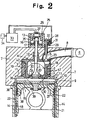
- Fig.2 is a fragmentary cross-sectional view of the second embodiment of this invention.
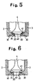
- Fig.3 - Fig.6 are explanatory drawing by which the state of control valve motion in the second embodiment of this invention.
- Fig.1 is a fragmentary cross-sectional view of the first embodiment of the high compression ratio engine related to this invention.
- 101 denote a cylinder and the cylinder 101 has a piston 102 which can be moved up and down by this cylinder 101.
- an inlet valve or an exhaust valve 164 and pre-chamber 103 which becomes precombustion chamber in cylinder head 111.
- the material which composes piston head 121 is ceramics to which has heat resistance by high strength.
- the pre-chamber 103 is consist from a high strength, heat resistance, and heat insulation material for example like the silicon nitride .
- Stem 141 of control valve 104 is slidably supported in an axis hole 133 which penetrates through a central upper part of the wall of pre-chamber 103. Therefore this control valve 104 can move in the direction of the axis of stem 141 by the vertical motion.
- a heat insulation material 134 is installed above axis hole 133 and heat in pre-chamber is prevented from running away from stem 141 of control valve 104.
- An electromagnetic device 105 is installed above stem 141 for the opening and shutting control valve 104.
- the fuel injection instruction of fuel injection pump (not shown) is commanded by controller 107.
- the controller 107 is composed by the microcomputer.
- the detection signal from rotation sensor 171, load sensor 172, and crank axis position sensing device 173 of the engine is input to the controller 107.
- a fixed operation is done in the controller 107.
- the contoroller 107 command the operation for injection pump or electromagnetic device 105 by the program stored in the contoroller 107.
- connection hole 131 is closed by the control valve 104, and air flow into the cylinder from inlet valve. Then compression step of the engine, the air in the cylinder is compressed by piston. And last period of compression step, the electromagnetic device 105 is operated, then connection hole 131 is opened by the valve 104. Before the connection hole 131 is opened, fuel has injected by the injection nozzle 106 to the pre-chamber 103. The fuel in the pre-chamber 103 is activated by remained exhaust gas in the pre-chamber 103.
- connection hole 131 is opened by the control valve 104 at the last period of compression step, compressed and hot air isdocument to the pre-chamber 103.
- the activated fuel is mixed by the air and is burning by the hot air, but the fuel in the pre-chamber is so rich that the generation of NOX is controlled.
- the non-burned fuel and flame generated in pre-chamber 3 is ejected for main chamber 112, and fuel and hot air in the main chamber 112 are reacted, then combuston ends. Therefore, the supplied fuel smoothly burns in the cylinder even if the compression ratio of the engine is raised.
- camshaft and the cogwheel device can be used as driving means of the control valve.
- Fig.2 is a fragmentary cross-sectional view of the second embodiment of this invention
- Fig.3 - Fig.6 are explanatory drawing by which the state of control valve motion in the second embodiment of this invention.
- the engine has subsidiary chamber 2 formed with side wall 3 of the heat insulating structure arranged in hole part 19 formed to cylinder head 7 and cylinder head 7 fixed to cylinder block 14 and cylinder block 14.
- the engine has a cylinder 22 fixed in a hole 21 on the cylinder block 14, piston 15, heat insulated main chamberl and connection hole 30 connected between main chamber1 and pre-chamber 2.
- Fuel inlet 23 is formed in a wall of pre-chamber3 and the gas fuel of a natural gas from fuel supply source 6 etc. is supplied to pre-chamber 2 by fuel inlet 23 through fuel passage 8.
- Fuel supply valve 5 to open and shut fuel inlet 23 is arranged in cylinder head 7.
- the gas engine with this pre-chamber has main connection passage 20 by which composed between main chamber 1 and pre-chamber 2 and sub-connection passage 30 by which composed surroundings of this main connection passage 20.
- control valve 4 which opens and shuts main connection passage 20 and sub-connection passage 30 is penetrated through the pre-chamber and the control valve 4 is arranged in cylinder head 7.
- control valve 4 has protrusion 40 which engages with main connection passage 20 and valve face 41 on a conic side which fit to the valve sheet 24 to close the sub-connection passage 30.
- sub-connection passage 30 is inclined from valve sheet 24 to wall of cylinder, and main connection passage 20 formed in the centre of cylinder.
- the sectional area of main connection passage 20 is larger than it of the sub-connection passage 30.
- Control valve 4 is controled by controller 33.
- the control valve 4 has a solenoid valve drive unit 25 which is controlled by the instruction of controller 33.
- the control valve 4 which is driven by electromagnetic force, opens sub-connection passage 30 first, and then opens main connection passage 20 next.
- the control valve 4 is driven by double lift motion movement.
- Solenoid valve drive unit 25 is composed of the return spring 13 to which control valve 4 is returned by the demagnetization of core 26 and the coil 27 wound on the core 26 which arranged in case 35 the first iron plate 16 and the second iron plate 17 fixed to valve stem 12 .
- the first iron plate 16 and the second iron plate 17 are rectangler plate.
- the first iron plate 16 is fixed on the top of valve stem 12 and the second iron plate 17 is fitted loosely to the valve stem 12. and then there are arranged in a mutually orthogonal state of intersection when sees from the plane.
- first iron plate 16 and second iron plate 17 are dispose oppose positon each other. Therefore, when a small current flows to electromagnetic coil 27 by the instruction of controller 33, small electromagnetic force rises to core 26 and applying power and the first iron plate 16 is adsorbed core 26 and control valve 4 rises slightly.
- Valve face 41 on a conic side parts from valve seat 24, sub-connection passage 30 opens, if control valve 4 rises slightly, and the valve 4 becomes a minuteness small opening.
- the second iron plate 17 in the position where big electromagnetic force is far from applying power and core 26 is adsorbed core 26 by core 26 and control valve 4 rises largely.
- Protrusion 40 comes out from main connection passage 20, if control valve 4 rises largely and main connection passage 20 opens.
- Solenoid valve drive unit 28 is composed by electrmagnetic coil 31 arranged to the core 29, iron plate 32 adsorbed by core 29 and return spring (not show) which closes fuel inlet 23 by fuel supply valve 5.
- main chamber 1 is formed with head liner 10 which is engaged with hole 9 formed to cylinder head 7.
- Head liner 10 which made from ceramics such as the nitride silicon, is composed of lower side part 11 of the head and upper part 36 of the liner where a part of cylinder 18, and heat insulation layer is formed the surface of the head liner 10( not showed).
- a wall 3 of the pre-chamber 2 is arranged on lower side part 11 of the head.
- the wall of the pre-chamber 3 is made from ceramics such as the nitride silicon and heat insulation materials 42 such as the ceramics fibers and the titanic acid aluminum are formed the face of the wall of pre-chamber 3.
- the inlet and outlet port can be formed cylinder head 7 or under the cylinder and inlet valve and exhaust valve are arranged in the inlet and outlet port.
- the fuel supply source 6 can be composed from a natural gas fuel tank, a natural gas accumulator. And natural gas is supplied from inlet 23 only a necessary amount to pre-chamber 2 by opening fuel supply valve 5 through fuel passage 8. Moreover, connection passage valve 4 is manufactured with ceramics such as excellent nitride silicon and carbonization silicon in heat resistance which has high temperature strength because of becoming a high temperature in the area of main connection passage 20 and sub-connection passage 30 because of combustion gas.
- Piston 15 is composed of piston skirt 38 fixed by the metal flow with uniting ring 39 to piston head 37 and piston head 37 which consists of ceramics such as excellent nitride silicon in heat resistance cylinder liner 22 is made with ceramics such as excellent nitride silicon in the sliding characteristic.
- This gas engine is the one operated by repeating four cycles of the inhalation stroke, compression stroke, expansion stroke, and exhaust stroke of the distance one by one.
- the opening and shutting drive is done by electromagnetic force by solenoid valve drive unit 25 and 28 with control valve 4 and fuel supply valve 5.
- control valve 4 opens a little, the combustion flame jetted to main combustion chamber as shown in Fig.4, and reached the outer area on the side around cylinder 18 through sub-report hole 30.
- the activated fuel is mixed by the air and is burning by the hot air, but the fuel in the pre-chamber is so rich that the generation of NOX is controlled. Afterwards, the non-burned fuel and flame generated in pre-chamber is ejected for main chamber, and fuel and hot air in the main chamber are reacted, then combuston ends. Therefore, the supplied fuel smoothly burns in the cylinder even if the compression ratio of the engine is raised. And the exhaust of nitrogen oxide NOx and the hydrocarbon hydrocarbon HC can be suppressed.
- fuel supply va3ve 5 opens at this time, the gas fuel of a natural gas of 2-3kg/cm2 introduces, and is closed and a fixed amount is introduced from fuel supply source 6 into pre-chamber 2 with main connection passage 20 and sub-connection passage 30 in this gas engine through fuel passage 8 at the inhalation distance. Therefore, when the gas fuel from fuel supply source 6 is introduced into pre-chamber 2, the gas fuel is received, is heated, and is activated in pre-chamber 2 because it is a state that main connection passage 20 and sub-connection passage 30 are closed with control valve 4 and remains in pre-chamber 2 the exhaust gas after burning.
- main connection passage 20 and sub-connection passage 30 are closed with the control valve 4 and can enlarge the compression ratio by compressing the inhalation air in main chamber 1 in this gas engine.
- control valve 4 is for instance pushed up by 20-30° in the vicinity of compression stroke the last stage before the edge of compression, control valve 4 opens sub-connection passage 30 first of all by driving solenoid valve drive unit 25, the air made a high temperature by high compression through sub-connection passage 30 introduces, and the air of about 20% is introduced from main chamber 1 to pre-chamber 2 for instance.
- pre-chamber 2 When the compressed air flows in pre-chamber 2, if the ignition combustion doing and combustion progress mixing and the pressure in pre-chamber 2 rises, grows more than the pressure of main chamber 1 and the combustion flame will spout from pre-chamber 2 to main chamber 1 with the gas fuel and air through sub-connection passage 30 and main connection passage 20.
- combustion gas which spouts from sub-connection hole 30 direct to outer of piston 15 in the first step operation of control valve 4 and main combustion gas spouts from main connection hole 20 next in the second step cperation of control valve 4.
- passage sectional area is largely formed at the center of the cylinder as for main connection passage 20, sub-connection passage 30 inclines toward the surrounding of cylinder 18 from valve seat 24, is formed the passage sectional area small, and a small amount of spouting is done from sub-connection passage 30 with the valve lift in the first step of control valve 4 and a large amount of combustion flame is spouted from main connection passage 1 by the valve lift in the second step.
- control valve 4 is compressed the inhalation air of main chamber 1 of this gas engine by piston's 15 of the compression stroke rising, is compressed air in main chamber 1, and overcomes the pressure in pre-chamber 2 by the pressure of main chamber 1 and is pushed up, the driving force of control valve 4 can remain and be not large.
- control valve 4 As for control valve 4 pushed up once, the state is maintained until the connection passage is opened, the control vaslve is maintained with the electromagnet as opening, and combustion ends. As for control valve 4 returns to former position by retur spring 13, first of all main connection passage 20 closes, control valve 4 descends next by gravity, and sub-connection passage 30 is closed with the end of combustion.
- Sub-connection passage 30 and main connection passage 20 are closed so that the gas fuel should not flow out from pre-chamber 2 to main chamber 1 through sub-connection passage 30 and main connection passage 20 when the fuel is supplied to pre-chamber 2.
- Load sensor 34 which detects the engine load is installed in this gas engine and the detection signal of this sensor 34 is input by controller 33.
- the engine load can be detected by measuring the amount of the fuel supply.
- Controller 33 is composed the fuel supply valve 5 responds to the engine load of the partial load and the full load and to control the open valve period.
- the amount to pre-chamber 2 of the gas fuel supply can be controlled by shortening the open speech period of the engine of fuel supply valve 5 at a partial load and lengthening the open speech period of the engine of fuel supply valve 5 at all loads.
- this engine supplies the fuel from the pre-chamber to main combustion chamber at the end of the compression step, the oxide of nitrogen is not generated in this engine.
- an engine with pre-chamber further comprising a spark plug in an ore-chamber.
- This embodiment can be easily ignited compare the above mentioned embodiment.
- control valve 4 opens main connection passage 20 and sub-connection passage 30, the inhalation air of the high compression ratio flows from main chamber 1 to pre-chamber 2, the fuel gas and the inhalation air mix, and ignites, and burns at high speed in the state of a rich fuel with large equivalence ratio, and the generation of NOx is controlled.
- the flame is spouted to the part around cylinder 18, next, the main flame is spouting from centers of the cylinder 18, and mixture of air and the combustion flame in main chamber 1 uniformly, spouting the flame connects extremely ideal combustion .
Landscapes
- Engineering & Computer Science (AREA)
- Mechanical Engineering (AREA)
- General Engineering & Computer Science (AREA)
- Chemical & Material Sciences (AREA)
- Combustion & Propulsion (AREA)
- Ceramic Engineering (AREA)
- Chemical Kinetics & Catalysis (AREA)
- General Chemical & Material Sciences (AREA)
- Oil, Petroleum & Natural Gas (AREA)
- Physics & Mathematics (AREA)
- Geometry (AREA)
- Combustion Methods Of Internal-Combustion Engines (AREA)
Applications Claiming Priority (6)
| Application Number | Priority Date | Filing Date | Title |
|---|---|---|---|
| JP271072/92 | 1992-09-14 | ||
| JP4271072A JP3059309B2 (ja) | 1992-09-14 | 1992-09-14 | 燃焼室間制御弁 |
| JP32605892A JPH06146890A (ja) | 1992-11-11 | 1992-11-11 | ガスエンジンの制御装置 |
| JP326058/92 | 1992-11-11 | ||
| JP4332211A JP3038090B2 (ja) | 1992-11-19 | 1992-11-19 | 副燃焼室を持つガスエンジン |
| JP332211/92 | 1992-11-19 |
Publications (3)
| Publication Number | Publication Date |
|---|---|
| EP0588593A2 true EP0588593A2 (de) | 1994-03-23 |
| EP0588593A3 EP0588593A3 (de) | 1994-08-03 |
| EP0588593B1 EP0588593B1 (de) | 1997-11-12 |
Family
ID=27335875
Family Applications (1)
| Application Number | Title | Priority Date | Filing Date |
|---|---|---|---|
| EP93307224A Expired - Lifetime EP0588593B1 (de) | 1992-09-14 | 1993-09-14 | Brennkraftmaschine mit Vorkammer |
Country Status (3)
| Country | Link |
|---|---|
| US (1) | US5454356A (de) |
| EP (1) | EP0588593B1 (de) |
| DE (1) | DE69315154T2 (de) |
Cited By (9)
| Publication number | Priority date | Publication date | Assignee | Title |
|---|---|---|---|---|
| EP0798453A1 (de) * | 1996-03-25 | 1997-10-01 | Isuzu Ceramics Research Institute Co., Ltd. | Gasmotor mit Vorkammer |
| CN1969112B (zh) * | 2004-06-10 | 2011-04-20 | 上村一郎 | 独立燃烧室式内燃机 |
| DE202013102541U1 (de) | 2013-06-12 | 2013-06-21 | Ford Global Technologies, Llc | Verbrennungsmotor |
| DE102013210965B3 (de) * | 2013-06-12 | 2014-09-04 | Ford Global Technologies, Llc | Verbrennungsmotor, sowie Verfahren zum Steuern des Betriebs eines Verbrennungsmotors |
| DE102013210966A1 (de) | 2013-06-12 | 2014-12-18 | Ford Global Technologies, Llc | Verbrennungsmotor, sowie Verfahren zum Steuern des Betriebseines Verbrennungsmotors |
| DE102017114390B3 (de) * | 2017-06-28 | 2018-11-08 | Maximilian Bierl | Gaseinbringvorrichtung, Verbrennungsmotor und Betriebsverfahren |
| DE102017012222A1 (de) | 2017-06-28 | 2019-01-03 | Maximilian Bierl | Gaseinbringvorrichtung, Verbrennungsmotor und Betriebsverfahren |
| FR3085718A1 (fr) * | 2018-09-10 | 2020-03-13 | Vianney Rabhi | Dispositif de rappel magnetique de clapet |
| WO2021160944A1 (fr) * | 2020-02-14 | 2021-08-19 | Vianney Rabhi | Prechambre d'allumage a clapet a sens de combustion inverse |
Families Citing this family (40)
| Publication number | Priority date | Publication date | Assignee | Title |
|---|---|---|---|---|
| AU2976197A (en) * | 1996-05-28 | 1998-01-05 | Hiroyasu Tanigawa | Energy conservation cycle engine |
| DE19624964A1 (de) * | 1996-06-22 | 1998-01-02 | Motoren Werke Mannheim Ag | Zündsystem für einen Gasmotor |
| US5778849A (en) * | 1997-05-05 | 1998-07-14 | Chrysler Corporation | Insulated precombustion chamber |
| DE19721756C1 (de) * | 1997-05-24 | 1998-08-06 | Daimler Benz Ag | Verfahren zum Betrieb einer Hubkolbenbrennkraftmaschine |
| US6340013B1 (en) * | 1997-07-03 | 2002-01-22 | Richard Berkeley Britton | Four-stroke internal combustion engine with recuperator in cylinder head |
| JP3695085B2 (ja) * | 1997-09-08 | 2005-09-14 | いすゞ自動車株式会社 | ガスエンジンの燃焼室構造 |
| US20070228193A1 (en) * | 2006-03-31 | 2007-10-04 | Aisan Kogyo Kabushiki Kaisha | Fuel injector |
| US8613272B2 (en) * | 2007-08-22 | 2013-12-24 | Hoerbiger Kompressortechnik Holding Gmbh | Spark-ignited gas engine |
| US20090145398A1 (en) * | 2007-11-08 | 2009-06-11 | Kemeny Zoltan A | Internal combustion engines with surcharging and supraignition systems |
| US20100229806A1 (en) * | 2007-11-08 | 2010-09-16 | Kemeny Zoltan A | Internal combustion engines with surcharging and supraignition systems |
| HUE026544T2 (hu) * | 2009-06-29 | 2016-06-28 | Jenoe Polgar | A lökettérfogattól szelepekkel elválasztott égéskamrájú belsõégésû motor, és eljárás módosított kontrollált öngyulladás megvalósítására az égéskamrában |
| US20120160217A1 (en) * | 2009-09-11 | 2012-06-28 | Toyota Jidosha Kabushiki Kaisha | Combustion pressure controller |
| US8584648B2 (en) | 2010-11-23 | 2013-11-19 | Woodward, Inc. | Controlled spark ignited flame kernel flow |
| US9172217B2 (en) | 2010-11-23 | 2015-10-27 | Woodward, Inc. | Pre-chamber spark plug with tubular electrode and method of manufacturing same |
| US9476347B2 (en) | 2010-11-23 | 2016-10-25 | Woodward, Inc. | Controlled spark ignited flame kernel flow in fuel-fed prechambers |
| US10161296B2 (en) | 2012-11-27 | 2018-12-25 | Board Of Trustees Of Michigan State University | Internal combustion engine |
| US9856848B2 (en) | 2013-01-08 | 2018-01-02 | Woodward, Inc. | Quiescent chamber hot gas igniter |
| US9765682B2 (en) | 2013-06-10 | 2017-09-19 | Woodward, Inc. | Multi-chamber igniter |
| JP6580701B2 (ja) | 2015-03-20 | 2019-09-25 | ウッドワード, インコーポレーテッドWoodward, Inc. | 並行予燃焼チャンバ点火システム |
| US9653886B2 (en) | 2015-03-20 | 2017-05-16 | Woodward, Inc. | Cap shielded ignition system |
| US20160348569A1 (en) * | 2015-05-28 | 2016-12-01 | Caterpillar Inc. | Combustion Pre-Chamber and Method for Operating Same |
| CL2015002015A1 (es) * | 2015-07-17 | 2015-10-02 | Pérez Gutiérrez Carlos | Sistema de admisión y escape de gases al cilindro del motor de combustión interna de cuatro tiempos con una cámara de intercambio de gases que permite a las válvulas del cilindro actuar con doble función de admisión y escape; y que pueden ser accionadas electrónicamente. |
| DE102015213814A1 (de) * | 2015-07-22 | 2017-01-26 | Robert Bosch Gmbh | Einspritzventil, Abgasnachbehandlungssystem |
| US9556832B1 (en) * | 2015-09-01 | 2017-01-31 | Combustion Engine Technologies, LLC | Adiabatic fuel injection-ignition method and device |
| US9890689B2 (en) | 2015-10-29 | 2018-02-13 | Woodward, Inc. | Gaseous fuel combustion |
| US9441573B1 (en) | 2015-12-09 | 2016-09-13 | Combustion Engine Technologies, LLC | Two-stroke reciprocating piston injection-ignition or compression-ignition engine |
| US20170241380A1 (en) * | 2016-02-22 | 2017-08-24 | Donald Joseph Stoddard | Liquid fuel based engine system using high velocity fuel vapor injectors |
| AT518584B1 (de) * | 2016-05-11 | 2018-02-15 | Ge Jenbacher Gmbh & Co Og | Verfahren zum Erkennen der Gasmenge |
| US11187142B2 (en) | 2017-08-01 | 2021-11-30 | Board Of Trustees Of Michigan State University | Diesel engine with turbulent jet ignition |
| US10890133B2 (en) * | 2018-09-10 | 2021-01-12 | Vianney Rabhi | Magnetic valve recoil device |
| US11408329B2 (en) | 2019-12-19 | 2022-08-09 | Board Of Trustees Of Michigan State University | Engine turbulent jet ignition system |
| US11255284B2 (en) * | 2020-02-26 | 2022-02-22 | Ford Global Technologies, Llc | Systems and methods for catalyst heating during cold-start with an active pre-chamber |
| US11085402B1 (en) * | 2020-04-01 | 2021-08-10 | Ford Global Technologies, Llc | Methods and systems for operating an adjustable pre-chamber |
| DE112021002882T5 (de) | 2020-05-20 | 2023-05-17 | Board Of Trustees Of Michigan State University | Brennkraftmaschine mit mehreren kraftstoffeinspritzungen ausserhalb einer vorkammer |
| US11867114B2 (en) * | 2020-10-16 | 2024-01-09 | Vianney Rabhi | Guide stud valve |
| US11078826B1 (en) * | 2020-10-28 | 2021-08-03 | Caterpillar Inc. | Gaseous fuel engine and sparkless operating strategy therefor |
| US11156147B1 (en) * | 2020-12-02 | 2021-10-26 | Aramco Services Company | Prechamber device for internal combustion engine |
| US11293337B1 (en) * | 2021-04-16 | 2022-04-05 | Ford Global Technologies, Llc | Systems and methods for adjustable pre-chamber |
| CN113027595A (zh) * | 2021-04-29 | 2021-06-25 | 林永男 | 具有组合燃烧室的活塞发动机及其工作方法 |
| WO2023055475A2 (en) | 2021-07-30 | 2023-04-06 | Board Of Trustees Of Michigan State University | Actuation system for an internal combustion engine |
Family Cites Families (5)
| Publication number | Priority date | Publication date | Assignee | Title |
|---|---|---|---|---|
| US4372264A (en) * | 1979-12-26 | 1983-02-08 | Trucco Horacio A | Internal combustion engine for diverse fuels |
| US4300497A (en) * | 1980-06-30 | 1981-11-17 | Rockwell International Corporation | Prevaporizing diesel precombustion chamber |
| AU609449B2 (en) * | 1986-10-24 | 1991-05-02 | Kabushiki Kaisha Hareyama Giken | Internal combustion engine |
| JPH086587B2 (ja) * | 1988-10-28 | 1996-01-24 | いすゞ自動車株式会社 | 副燃焼室式断熱エンジン |
| US5067458A (en) * | 1989-03-27 | 1991-11-26 | Caterpillar Inc. | Fuel combustion system and method of operation for an otto-cycle internal combustion engine |
-
1993
- 1993-09-14 DE DE69315154T patent/DE69315154T2/de not_active Expired - Fee Related
- 1993-09-14 EP EP93307224A patent/EP0588593B1/de not_active Expired - Lifetime
- 1993-09-14 US US08/120,348 patent/US5454356A/en not_active Expired - Fee Related
Cited By (16)
| Publication number | Priority date | Publication date | Assignee | Title |
|---|---|---|---|---|
| EP0798453A1 (de) * | 1996-03-25 | 1997-10-01 | Isuzu Ceramics Research Institute Co., Ltd. | Gasmotor mit Vorkammer |
| US5950593A (en) * | 1996-03-25 | 1999-09-14 | Isuzu Ceramics Research Institute Co., Ltd. | Gas engine with pre-combustion chamber |
| US6073605A (en) * | 1996-03-25 | 2000-06-13 | Isuzu Ceramics Research Institute Co. | Gas engine with pre-combustion chamber |
| CN1969112B (zh) * | 2004-06-10 | 2011-04-20 | 上村一郎 | 独立燃烧室式内燃机 |
| DE202013102541U1 (de) | 2013-06-12 | 2013-06-21 | Ford Global Technologies, Llc | Verbrennungsmotor |
| DE102013210965B3 (de) * | 2013-06-12 | 2014-09-04 | Ford Global Technologies, Llc | Verbrennungsmotor, sowie Verfahren zum Steuern des Betriebs eines Verbrennungsmotors |
| DE102013210966A1 (de) | 2013-06-12 | 2014-12-18 | Ford Global Technologies, Llc | Verbrennungsmotor, sowie Verfahren zum Steuern des Betriebseines Verbrennungsmotors |
| DE102017012222A1 (de) | 2017-06-28 | 2019-01-03 | Maximilian Bierl | Gaseinbringvorrichtung, Verbrennungsmotor und Betriebsverfahren |
| DE102017114390B3 (de) * | 2017-06-28 | 2018-11-08 | Maximilian Bierl | Gaseinbringvorrichtung, Verbrennungsmotor und Betriebsverfahren |
| DE102017012222B4 (de) | 2017-06-28 | 2021-07-22 | Maximilian Bierl | Gaseinbringvorrichtung, Verbrennungsmotor und Betriebsverfahren |
| FR3085718A1 (fr) * | 2018-09-10 | 2020-03-13 | Vianney Rabhi | Dispositif de rappel magnetique de clapet |
| WO2020053501A1 (fr) * | 2018-09-10 | 2020-03-19 | Vianney Rabhi | Dispositif de rappel magnetique de clapet |
| AU2019338970B2 (en) * | 2018-09-10 | 2025-06-05 | Vianney Rabhi | Magnetic valve return device |
| WO2021160944A1 (fr) * | 2020-02-14 | 2021-08-19 | Vianney Rabhi | Prechambre d'allumage a clapet a sens de combustion inverse |
| FR3107305A1 (fr) * | 2020-02-14 | 2021-08-20 | Vianney Rabhi | Prechambre d’allumage a clapet a sens de combustion inverse |
| CN115023541A (zh) * | 2020-02-14 | 2022-09-06 | V·拉比 | 具有反向燃烧的阀控点火预燃室 |
Also Published As
| Publication number | Publication date |
|---|---|
| EP0588593A3 (de) | 1994-08-03 |
| EP0588593B1 (de) | 1997-11-12 |
| DE69315154D1 (de) | 1997-12-18 |
| DE69315154T2 (de) | 1998-03-05 |
| US5454356A (en) | 1995-10-03 |
Similar Documents
| Publication | Publication Date | Title |
|---|---|---|
| EP0588593A2 (de) | Brennkraftmaschine mit Vorkammer | |
| CN101443540B (zh) | 将气体燃料喷射入内燃机的方法 | |
| US5115790A (en) | Re-combustion control means for alcohol engine | |
| EP0595473B1 (de) | Gasbrennkraftmaschine mit Vorkammer | |
| JPH084562A (ja) | マルチヒューエルエンジン | |
| EP0597713B1 (de) | Steuereinheit für hochverdichtende Motoren unter Verwendung von verdampfenden Kraftstoffen | |
| US5603298A (en) | High compression ratio internal-combustion engine | |
| WO2002079623A1 (en) | Method of controlling the injection of fluid into an internal combustion engine | |
| JP4086440B2 (ja) | エンジン | |
| JP3069454B2 (ja) | 副燃焼室を持つガスエンジン | |
| EP0588592B1 (de) | Hochverdichtende Brennkraftmaschine | |
| JP3038090B2 (ja) | 副燃焼室を持つガスエンジン | |
| EP4424981B1 (de) | Verfahren zum betreiben einer verbrennungskraftmaschinenanlage unter verwendung von wasserstoff-kraftstoff | |
| JPH0754656A (ja) | エンジンの燃焼室 | |
| JPH06159061A (ja) | セラミックバルブを用いたガスエンジン | |
| JPH06229320A (ja) | 直噴式高圧縮比ガスエンジン | |
| JP3000246B2 (ja) | ガス用エンジンの燃焼室 | |
| JPH06159063A (ja) | 点火装置を備えたガスエンジン | |
| JP2000136724A (ja) | 主室容積可変手段を持つガスエンジン | |
| JPH0972269A (ja) | 着火装置を持つ副燃焼室式ガスエンジン | |
| JPH06323209A (ja) | 副室を備えたアルコール改質エンジン | |
| JPH07127529A (ja) | 2層副室を有する遮熱型ガスエンジン | |
| JPH08326545A (ja) | 2サイクルガソリンエンジンの燃焼装置 | |
| JP2006002719A (ja) | 内燃機関の制御装置 | |
| JPH0754717A (ja) | エンジンの燃焼室 |
Legal Events
| Date | Code | Title | Description |
|---|---|---|---|
| PUAI | Public reference made under article 153(3) epc to a published international application that has entered the european phase |
Free format text: ORIGINAL CODE: 0009012 |
|
| AK | Designated contracting states |
Kind code of ref document: A2 Designated state(s): DE FR GB |
|
| PUAL | Search report despatched |
Free format text: ORIGINAL CODE: 0009013 |
|
| AK | Designated contracting states |
Kind code of ref document: A3 Designated state(s): DE FR GB |
|
| 17P | Request for examination filed |
Effective date: 19940929 |
|
| 17Q | First examination report despatched |
Effective date: 19950613 |
|
| GRAG | Despatch of communication of intention to grant |
Free format text: ORIGINAL CODE: EPIDOS AGRA |
|
| GRAH | Despatch of communication of intention to grant a patent |
Free format text: ORIGINAL CODE: EPIDOS IGRA |
|
| GRAH | Despatch of communication of intention to grant a patent |
Free format text: ORIGINAL CODE: EPIDOS IGRA |
|
| GRAA | (expected) grant |
Free format text: ORIGINAL CODE: 0009210 |
|
| AK | Designated contracting states |
Kind code of ref document: B1 Designated state(s): DE FR GB |
|
| REF | Corresponds to: |
Ref document number: 69315154 Country of ref document: DE Date of ref document: 19971218 |
|
| ET | Fr: translation filed | ||
| PLBE | No opposition filed within time limit |
Free format text: ORIGINAL CODE: 0009261 |
|
| STAA | Information on the status of an ep patent application or granted ep patent |
Free format text: STATUS: NO OPPOSITION FILED WITHIN TIME LIMIT |
|
| 26N | No opposition filed | ||
| PGFP | Annual fee paid to national office [announced via postgrant information from national office to epo] |
Ref country code: DE Payment date: 20000904 Year of fee payment: 8 |
|
| PGFP | Annual fee paid to national office [announced via postgrant information from national office to epo] |
Ref country code: FR Payment date: 20000912 Year of fee payment: 8 |
|
| PGFP | Annual fee paid to national office [announced via postgrant information from national office to epo] |
Ref country code: GB Payment date: 20000913 Year of fee payment: 8 |
|
| PG25 | Lapsed in a contracting state [announced via postgrant information from national office to epo] |
Ref country code: GB Free format text: LAPSE BECAUSE OF NON-PAYMENT OF DUE FEES Effective date: 20010914 |
|
| REG | Reference to a national code |
Ref country code: GB Ref legal event code: IF02 |
|
| GBPC | Gb: european patent ceased through non-payment of renewal fee |
Effective date: 20010914 |
|
| PG25 | Lapsed in a contracting state [announced via postgrant information from national office to epo] |
Ref country code: DE Free format text: LAPSE BECAUSE OF NON-PAYMENT OF DUE FEES Effective date: 20020501 |
|
| PG25 | Lapsed in a contracting state [announced via postgrant information from national office to epo] |
Ref country code: FR Free format text: LAPSE BECAUSE OF NON-PAYMENT OF DUE FEES Effective date: 20020531 |
|
| REG | Reference to a national code |
Ref country code: FR Ref legal event code: ST |