EP0588343A1 - Vorrichtung zum Entfernen und Sammeln von Staub und Abfall für eine Doppelt-Strickmaschine - Google Patents
Vorrichtung zum Entfernen und Sammeln von Staub und Abfall für eine Doppelt-Strickmaschine Download PDFInfo
- Publication number
- EP0588343A1 EP0588343A1 EP93114930A EP93114930A EP0588343A1 EP 0588343 A1 EP0588343 A1 EP 0588343A1 EP 93114930 A EP93114930 A EP 93114930A EP 93114930 A EP93114930 A EP 93114930A EP 0588343 A1 EP0588343 A1 EP 0588343A1
- Authority
- EP
- European Patent Office
- Prior art keywords
- knitting
- section
- suction fan
- hood
- dust
- Prior art date
- Legal status (The legal status is an assumption and is not a legal conclusion. Google has not performed a legal analysis and makes no representation as to the accuracy of the status listed.)
- Granted
Links
Images

Classifications
-
- D—TEXTILES; PAPER
- D04—BRAIDING; LACE-MAKING; KNITTING; TRIMMINGS; NON-WOVEN FABRICS
- D04B—KNITTING
- D04B35/00—Details of, or auxiliary devices incorporated in, knitting machines, not otherwise provided for
- D04B35/32—Devices for removing lint or fluff
Definitions
- This invention constitutes an improvement upon the dust collection systems for circular knitting machines disclosed in the commonly owned United States Patent No. 5,177,985, issued January 12, 1993 and co-pending patent applications Serial No. 08/024,508, filed March 2, 1993, and Serial No. 07/940,512, filed September 4, 1992.
- This invention relates to the removal and collection of dust and other waste from the components of circular knitting machines and more particularly to the removal thereof from double knitting machines.
- Double knitting machines have needles in the cylinder and needles in a dial cooperating with the cylinder needles in producing a double knit fabric. Such double knitting machines have particular dust and waste generation problems that are distinct from other circular knitting machines.
- a waste removal and collection system including a suction fan mounted above the cylinder and dial of a double knitting machine for creating an air stream flowing upwardly across the knitting components of the cylinder and inwardly across the yarn feed and yarn guiding components of the double knitting machine.
- An air stream confining hood overlies and extends outwardly beyond the outer periphery of the needle cylinder and dial of the double knitting machine to receive and confine the upwardly flowing air stream and dust and other waste entrained therein.
- a circularly movable fan or other air blowing means moves around the knitting machine blowing air inwardly across the yarn feeding and yarn guiding components to assist the suction fan in removing dust and other waste therefrom.
- a waste collection system communicates with the suction fan to receive the air stream and entrained waste from the suction fan and to separate the waste from the air stream.
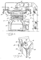
- the knitting section 12 of the double knitting machine 10 includes a needle cylinder 18 and a needle dial 20 .
- Needle cylinder 18 has cylinder needles (not shown) vertically slidable in a multiplicity of needle grooves formed in the outer periphery of needle cylinder 18 .
- dial 20 has dial needles (also not shown) radially slidable in a multiplicity of needle grooves in the dial 20 .
- the cylinder 18 and dial 20 rotate at a synchronized speed by a drive means (not shown) with which the double knitting machine 10 is conventionally equipped.
- the knitting section 12 is supplied with yarns from a creel (not shown) by yarn feeding and guiding means 22 in a manner that is well known.
- the knitting section 12 and yarn feeding and guiding means 22 generate dust and other fiber waste during operation thereof.
- a fiber waste removal and collection system which partially overlies the knitting section 12 .
- System 24 includes a suction fan 26 confined within a housing 28 which is open at the bottom thereof. Fan 26 is driven by a motor 29 to create an air stream flowing upwardly through and across knitting section 12 including the cylinder 18 and dial 20 and an air stream flowing inwardly across the yarn feeding and guiding means 22 .
- System 24 further includes an air stream confining or suction hood 30 which overlies the knitting section 12 and is supported from bed 14 by secondary frame members 32 .
- Hood 30 includes a generally cylindrical section 34 which is of a diameter generally consistent with the diameter of the bed 14 such that the hood 30 overlies and surrounds the knitting section 12 to capture and confine substantially all of the upwardly flowing air stream and waste entrained therein.
- Hood 30 further includes a frusto-conical section 36 which extends upwardly and inwardly from cylindrical section 34 to a position immediately below but spaced from the open bottom of housing 28 of suction fan 26 .
- Frusto-conical section 36 has an opening 38 at its upper terminus such that the interior of hood 30 communicates with fan 26 .
- Suction hood 30 also includes a second, internal frusto-conical section or member 40 which is solid and is spaced inwardly of frusto-conical section 36 to define a restricted circumferential air passageway 42 through hood 30 . Because the suction hood 30 is of greater diameter than the knitting section 12 and because of the presence of the member 40 therein, the upwardly flowing air stream passing across the knitting section 12 moves radially outwardly thereacross and carries all entrained dust and other fiber waste upwardly and outwardly beyond the periphery of knitting section 12 before the air stream and entrained fiber waste passes into the air passageway 42 .
- a door or movable extension 44 be provided between the lower end of cylindrical section 34 and the top of the bed 14 (as seen in Figure 3) to enclose completely the knitting section 12 .
- the door or movable extension 44 should be constructed to have movable panels or sections to provide access to the knitting section 12 as needed for proper operation thereof.
- hood 30 is polygonal in plan and is formed of twelve (12) interconnected sections.
- hood 30 may be of any suitable construction and configuration, such as cylindrical.
- support brackets 46 are mounted on a head part 48 of knitting machine 10 and extend upwardly and outwardly therefrom. Brackets 46 pass through openings 49 in frusto-conical section 36 of hood 30 to the yarn feeding and guiding means 22 .
- hood 30 must also be provided with suitable access openings between yarn feeding and guiding means 22 and the knitting section 12 .
- the location and configuration of such access openings will depend upon the particular yarn feeding and guiding means 22 with which knitting machine 10 is equipped and will be well within the skill of knitting technicians.
- an air jet 50 be provided within hood 30 for blasting air against the knitting components of needle cylinder 18 and dial 20 .
- a mounting and drive mechanism 52 for air jet 50 is carried by head part 48 ( Figure 3).
- the air jet 50 and its mounting and drive mechanism 52 are more particularly and specifically described in commonly owned United States Patent No. 4,703,632, issued November 3, 1987, the disclosure of which is incorporated herein by reference.
- a pair of traveling blowers or fans 54 , 56 are mounted outwardly of the yarn feeding and guiding means 22 for blowing relatively high velocity air streams inwardly across the yarn feeding and guiding means. These high velocity air streams assist suction fan 26 in removing fiber waste from the yarn feeding and guiding means 22 and in conveying such waste into fan housing 28 .
- Blowers or fans comparable to blowers 54 , 56 and the mounting and driving means therefor are specifically disclosed in the commonly owned United States Patent No. 5,177,985, issued January 12, 1993, which disclosure is incorporated herein by reference.
- a duct 58 is connected at one end to the discharge end of suction fan housing 28 and at its other end to a dust and other fiber waste collection means 60 .
- Duct 58 is preferably formed of sheet metal and waste collection means 60 is formed of a foraminous material to permit air to escape therethrough while entrapping and collecting the dust and fiber waste in collection means 60 .
- Duct 58 and waste collection means 60 are more specifically disclosed in the commonly owned, co-pending application, Serial No. 08/024,508, filed March 2, 1993, which disclosure is incorporated herein by reference.
- the double knitting machine 10 produces double knit cloth by knitting yarns on the cylinder needles and the dial needles.
- the yarns are supplied to the cylinder and dial needles by the yarn feeding and guiding means 22 .
- Considerable dust and other fiber waste is generated by the knitting section 12 and by the yarn feeding and guiding means 22 .
- the dust and other fiber waste removal and collection system 24 removes and collects such dust and other fiber waste in an improved and highly efficient manner.
- the dust and other fiber waste is removed from knitting section 12 by the suction fan 26 assisted by the air jet 50 .
- hood 30 Because the air passageway 42 within hood 30 is positioned radially outwardly of knitting section 12 , the upwardly flowing air stream created by suction fan 26 flows outwardly beyond the periphery of knitting section 12 , thereby carrying the entrained dust and other fiber waste not only upwardly from but outwardly of the knitting components of the knitting section 12 . Therefore, if any of the fiber waste drops out of the air stream, it will not fall back onto the knitting section 12 . Also, the surrounding relationship of hood 30 to the knitting section 12 , particularly if the door or extension 44 is utilized, confines the air stream's outward travel and obviates the need for curtains or other partitions between adjacent knitting machines. The frusto-conical shape of hood 30 confines and deflects the upwardly flowing air stream directly into suction fan housing 28 and past suction fan 26 .
- An inwardly flowing air stream is created by suction fan 26 assisted by blowers 54 , 56 .
- This inwardly flowing air stream removes dust and other fiber waste from the yarn feeding and guiding means 22 and other associated machine components. Because the yarn feeding and guiding means 22 are located radially outwardly of the knitting section 12 , the inwardly moving air stream takes the entrained dust and other fiber waste away from these knitting machine components.
- the hood 30 protects the knitting section 12 from any dust or other fiber waste that may drop from the inwardly flowing air stream.
- the inwardly flowing air stream enters the open bottom of suction fan housing 28 between such housing and the hood 30 and merges with the upwardly flowing air stream from the hood 30 .
- the merged air streams then pass through the duct 58 and into the waste collection means 60 .
- the air escapes from the waste collection means 60 but the dust and other fiber waste is entrapped therein and collected for subsequent disposal.
Applications Claiming Priority (2)
| Application Number | Priority Date | Filing Date | Title |
|---|---|---|---|
| JP4275449A JPH06101146A (ja) | 1992-09-18 | 1992-09-18 | 丸編機における繊維屑などの吸塵・排出装置 |
| JP275449/92 | 1992-09-18 |
Publications (2)
| Publication Number | Publication Date |
|---|---|
| EP0588343A1 true EP0588343A1 (de) | 1994-03-23 |
| EP0588343B1 EP0588343B1 (de) | 1997-12-03 |
Family
ID=17555687
Family Applications (1)
| Application Number | Title | Priority Date | Filing Date |
|---|---|---|---|
| EP93114930A Expired - Lifetime EP0588343B1 (de) | 1992-09-18 | 1993-09-16 | Vorrichtung und Methode zum Entfernen und Sammeln von Staub und Abfall für eine zweifonturige Strickmaschine |
Country Status (6)
| Country | Link |
|---|---|
| US (1) | US5379614A (de) |
| EP (1) | EP0588343B1 (de) |
| JP (1) | JPH06101146A (de) |
| KR (1) | KR940007251A (de) |
| DE (1) | DE69315518T2 (de) |
| ES (1) | ES2110041T3 (de) |
Cited By (5)
| Publication number | Priority date | Publication date | Assignee | Title |
|---|---|---|---|---|
| WO1996036754A1 (en) * | 1995-05-16 | 1996-11-21 | Alan Shelton Limited | Cleaning device for a knitting machine |
| CN104562424A (zh) * | 2015-02-03 | 2015-04-29 | 海宁汉德袜业有限公司 | 织袜机中的除尘装置 |
| CN104593941A (zh) * | 2015-02-03 | 2015-05-06 | 海宁汉德袜业有限公司 | 自动织袜机中的集尘机构 |
| CN105734820A (zh) * | 2015-02-03 | 2016-07-06 | 海宁汉德袜业有限公司 | 改进的织袜机中的除尘装置 |
| CN113322604A (zh) * | 2020-08-18 | 2021-08-31 | 山东玻纤集团股份有限公司 | 一种玻璃纤维纱线自动涂层装置 |
Families Citing this family (9)
| Publication number | Priority date | Publication date | Assignee | Title |
|---|---|---|---|---|
| EP0721518B1 (de) * | 1993-09-30 | 1997-12-17 | Alan Shelton Limited | Reinigungsanlage für strickmaschinen |
| US5431029A (en) * | 1994-03-17 | 1995-07-11 | Mayer Industries, Inc. | Method and apparatus for forming reverse loop sliver knit fabric |
| US5737942A (en) * | 1996-07-03 | 1998-04-14 | Alandale Industries, Inc. | Means for deterring lint and debris accumulation on the knitting elements of a circular knitting machine |
| US5956977A (en) * | 1997-07-14 | 1999-09-28 | Uniwave, Inc. | Dust control and cooling apparatus for circular knitting machines |
| GB0004062D0 (en) * | 1999-02-22 | 2000-04-12 | Yoo Chol | Method and apparatus for removing lints in circular knitting machine |
| US20040076501A1 (en) * | 2000-12-04 | 2004-04-22 | Mcgill Dennis E. | Apparatus for lifting and moving a workload |
| KR101975677B1 (ko) * | 2017-11-20 | 2019-05-07 | 양진석 | 환편기용 보풀 제거장치 |
| KR102590626B1 (ko) * | 2022-01-07 | 2023-10-17 | 에코융합섬유연구원 | 집진기능이 구비된 환편기 |
| CN114411329B (zh) * | 2022-01-24 | 2023-07-21 | 石狮市成鑫针织机械有限公司 | 一种方便拆装过滤板的自动除毛絮大圆机 |
Citations (7)
| Publication number | Priority date | Publication date | Assignee | Title |
|---|---|---|---|---|
| GB1160660A (en) * | 1967-07-26 | 1969-08-06 | Fouquet Werk Frauz & Planck | Apparatus for Removing Incidental Fibrous Fluff from Knitting Machines |
| DE1560928A1 (de) * | 1964-03-18 | 1970-03-19 | Brandi Ingenieurgmbh | Vorrichtung zur Bekaempfung der Staubbildung bei Strickmaschinen |
| CH489653A (de) * | 1966-09-05 | 1970-04-30 | Luwa Ag | Vorrichtung zum pneumatischen Entstauben der Arbeitszone von zentralsymmetrischen Textilmaschinen |
| DE1585177B1 (de) * | 1963-09-12 | 1970-10-15 | Morat Gmbh Franz | Rundraenderstrickmaschine |
| DE2448765A1 (de) * | 1974-10-12 | 1976-04-22 | Luwa Ag | Einrichtung zum pneumatischen reinigen von textilmaschinen |
| US4703632A (en) * | 1985-10-28 | 1987-11-03 | Precision Fukuhara Works, Ltd. | Lint removing apparatus for circular knitting machine |
| US5177985A (en) * | 1991-04-22 | 1993-01-12 | Precision Fukuhara Works, Ltd. | Collector/remover of dust of flocks in knitting machine |
Family Cites Families (9)
| Publication number | Priority date | Publication date | Assignee | Title |
|---|---|---|---|---|
| US2582092A (en) * | 1948-04-13 | 1952-01-08 | Ancet Victor Marie Joseph | Lint collector for circular looms |
| DE806279C (de) * | 1948-06-29 | 1951-06-14 | Josef Fischer | Vorrichtung zum Auffangen und Sammeln der Schnitthaare beim Haarschneiden |
| CH375643A (de) * | 1959-09-25 | 1964-02-29 | Rieter Ag Maschf | Faden- und Staubabsaugvorrichtung an einer Spinnmaschine |
| US3391528A (en) * | 1965-12-03 | 1968-07-09 | John C. Shackelford | Air handling and cleaning apparatus for machines |
| CH555918A (de) * | 1971-06-18 | 1974-11-15 | Luwa Ag | Einrichtung zum pneumatischen reinigen von textilmaschinen. |
| IT209232Z2 (it) * | 1985-10-14 | 1988-09-20 | Lonati Spa | Macchina circolare per laproduzione di calze e simili con schermo di protezione nella zona di lavorazione. |
| DE3635096A1 (de) * | 1986-10-15 | 1988-04-21 | Stoll & Co H | Entstaubungsvorrichtung fuer flachstrickmaschinen |
| CH674994A5 (de) * | 1988-01-22 | 1990-08-15 | Benninger Ag Maschf | |
| IL94477A0 (en) * | 1990-05-22 | 1991-03-10 | Maarachot Amlach 83 Ltd | Device for performing surgical implants |
-
1992
- 1992-09-18 JP JP4275449A patent/JPH06101146A/ja active Pending
-
1993
- 1993-05-13 KR KR1019930008218A patent/KR940007251A/ko not_active Application Discontinuation
- 1993-09-02 US US08/116,353 patent/US5379614A/en not_active Expired - Fee Related
- 1993-09-16 EP EP93114930A patent/EP0588343B1/de not_active Expired - Lifetime
- 1993-09-16 ES ES93114930T patent/ES2110041T3/es not_active Expired - Lifetime
- 1993-09-16 DE DE69315518T patent/DE69315518T2/de not_active Expired - Fee Related
Patent Citations (7)
| Publication number | Priority date | Publication date | Assignee | Title |
|---|---|---|---|---|
| DE1585177B1 (de) * | 1963-09-12 | 1970-10-15 | Morat Gmbh Franz | Rundraenderstrickmaschine |
| DE1560928A1 (de) * | 1964-03-18 | 1970-03-19 | Brandi Ingenieurgmbh | Vorrichtung zur Bekaempfung der Staubbildung bei Strickmaschinen |
| CH489653A (de) * | 1966-09-05 | 1970-04-30 | Luwa Ag | Vorrichtung zum pneumatischen Entstauben der Arbeitszone von zentralsymmetrischen Textilmaschinen |
| GB1160660A (en) * | 1967-07-26 | 1969-08-06 | Fouquet Werk Frauz & Planck | Apparatus for Removing Incidental Fibrous Fluff from Knitting Machines |
| DE2448765A1 (de) * | 1974-10-12 | 1976-04-22 | Luwa Ag | Einrichtung zum pneumatischen reinigen von textilmaschinen |
| US4703632A (en) * | 1985-10-28 | 1987-11-03 | Precision Fukuhara Works, Ltd. | Lint removing apparatus for circular knitting machine |
| US5177985A (en) * | 1991-04-22 | 1993-01-12 | Precision Fukuhara Works, Ltd. | Collector/remover of dust of flocks in knitting machine |
Cited By (7)
| Publication number | Priority date | Publication date | Assignee | Title |
|---|---|---|---|---|
| WO1996036754A1 (en) * | 1995-05-16 | 1996-11-21 | Alan Shelton Limited | Cleaning device for a knitting machine |
| CN104562424A (zh) * | 2015-02-03 | 2015-04-29 | 海宁汉德袜业有限公司 | 织袜机中的除尘装置 |
| CN104593941A (zh) * | 2015-02-03 | 2015-05-06 | 海宁汉德袜业有限公司 | 自动织袜机中的集尘机构 |
| CN105734820A (zh) * | 2015-02-03 | 2016-07-06 | 海宁汉德袜业有限公司 | 改进的织袜机中的除尘装置 |
| CN104562424B (zh) * | 2015-02-03 | 2016-08-24 | 海宁汉德袜业有限公司 | 织袜机中的除尘装置 |
| CN104593941B (zh) * | 2015-02-03 | 2017-01-18 | 海宁汉德袜业有限公司 | 自动织袜机中的集尘机构 |
| CN113322604A (zh) * | 2020-08-18 | 2021-08-31 | 山东玻纤集团股份有限公司 | 一种玻璃纤维纱线自动涂层装置 |
Also Published As
| Publication number | Publication date |
|---|---|
| DE69315518T2 (de) | 1998-04-09 |
| KR940007251A (ko) | 1994-04-26 |
| JPH06101146A (ja) | 1994-04-12 |
| EP0588343B1 (de) | 1997-12-03 |
| US5379614A (en) | 1995-01-10 |
| ES2110041T3 (es) | 1998-02-01 |
| DE69315518D1 (de) | 1998-01-15 |
Similar Documents
| Publication | Publication Date | Title |
|---|---|---|
| US5379614A (en) | Dust and waste removal and collection system for double knitting machine | |
| US5373711A (en) | Apparatus for cleaning the dust collector/remover filter | |
| EP0510508B1 (de) | Vorrichtung zum Sammeln und Entfernen von Flockenstaub an eine Strickmaschine | |
| US5333354A (en) | Device for collecting dust as fiber waste and the like on creel stand | |
| JPH0571054A (ja) | 編機における集塵・除去装置およびその制御方法 | |
| US5408850A (en) | Fiber waste collector/remover and cooling apparatus for use with a circular knitting machine | |
| US3535895A (en) | Apparatus for pneumatically cleaning the work zone of centrosymmetrical textile machines | |
| US5557949A (en) | Dust collecting and removing device in a circular knitting machine and a knit fabric manufacturing apparatus | |
| US4346497A (en) | Device for removing dust from a winding machine | |
| US3798886A (en) | Self-cleaning spinning arrangement for use with textile machines | |
| EP0510509A1 (de) | Flockenstaubentferner an einer Rundstrickmaschine | |
| JPH09170124A (ja) | 紡績機械におけるサクション装置 | |
| US5363676A (en) | Dust sucking and discharging device for fiber wastes on knitting machine | |
| JP2002173834A (ja) | カードに設けられる装置 | |
| US5852844A (en) | Suction apparatus for removing waste from a drawing frame inlet | |
| US5182903A (en) | Open-end spinning machine | |
| EP0168944B1 (de) | Staubabscheider für Streckwerke | |
| EP0721518B1 (de) | Reinigungsanlage für strickmaschinen | |
| EP0020524B1 (de) | Kardiervorrichtung | |
| US4224718A (en) | Pneumatic cleaning of the chamber carding elements of a textile machine | |
| WO1995019463B1 (en) | Knitting apparatus | |
| US5515698A (en) | Apparatus for removing and collecting fiber waste from a creel stand | |
| JPH026678A (ja) | 捩じられた或いは撚られた糸を造るための機械 | |
| WO1995019463A1 (en) | Knitting apparatus | |
| JP2550170B2 (ja) | 紡機における清掃装置 |
Legal Events
| Date | Code | Title | Description |
|---|---|---|---|
| PUAI | Public reference made under article 153(3) epc to a published international application that has entered the european phase |
Free format text: ORIGINAL CODE: 0009012 |
|
| AK | Designated contracting states |
Kind code of ref document: A1 Designated state(s): DE ES GB IT |
|
| 17P | Request for examination filed |
Effective date: 19940405 |
|
| 17Q | First examination report despatched |
Effective date: 19960126 |
|
| GRAG | Despatch of communication of intention to grant |
Free format text: ORIGINAL CODE: EPIDOS AGRA |
|
| GRAH | Despatch of communication of intention to grant a patent |
Free format text: ORIGINAL CODE: EPIDOS IGRA |
|
| GRAH | Despatch of communication of intention to grant a patent |
Free format text: ORIGINAL CODE: EPIDOS IGRA |
|
| GRAA | (expected) grant |
Free format text: ORIGINAL CODE: 0009210 |
|
| AK | Designated contracting states |
Kind code of ref document: B1 Designated state(s): DE ES GB IT |
|
| REF | Corresponds to: |
Ref document number: 69315518 Country of ref document: DE Date of ref document: 19980115 |
|
| REG | Reference to a national code |
Ref country code: ES Ref legal event code: FG2A Ref document number: 2110041 Country of ref document: ES Kind code of ref document: T3 |
|
| ITF | It: translation for a ep patent filed |
Owner name: LUNATI & MAZZONI S.A.S. |
|
| PG25 | Lapsed in a contracting state [announced via postgrant information from national office to epo] |
Ref country code: GB Free format text: LAPSE BECAUSE OF NON-PAYMENT OF DUE FEES Effective date: 19980916 |
|
| PG25 | Lapsed in a contracting state [announced via postgrant information from national office to epo] |
Ref country code: ES Free format text: LAPSE BECAUSE OF NON-PAYMENT OF DUE FEES Effective date: 19980917 |
|
| PLBE | No opposition filed within time limit |
Free format text: ORIGINAL CODE: 0009261 |
|
| STAA | Information on the status of an ep patent application or granted ep patent |
Free format text: STATUS: NO OPPOSITION FILED WITHIN TIME LIMIT |
|
| 26N | No opposition filed | ||
| GBPC | Gb: european patent ceased through non-payment of renewal fee |
Effective date: 19980916 |
|
| PG25 | Lapsed in a contracting state [announced via postgrant information from national office to epo] |
Ref country code: DE Free format text: LAPSE BECAUSE OF NON-PAYMENT OF DUE FEES Effective date: 19990701 |
|
| REG | Reference to a national code |
Ref country code: ES Ref legal event code: FD2A Effective date: 19991013 |
|
| PG25 | Lapsed in a contracting state [announced via postgrant information from national office to epo] |
Ref country code: IT Free format text: LAPSE BECAUSE OF NON-PAYMENT OF DUE FEES;WARNING: LAPSES OF ITALIAN PATENTS WITH EFFECTIVE DATE BEFORE 2007 MAY HAVE OCCURRED AT ANY TIME BEFORE 2007. THE CORRECT EFFECTIVE DATE MAY BE DIFFERENT FROM THE ONE RECORDED. Effective date: 20050916 |