EP0587586B1 - Closing, separating or covering device - Google Patents
Closing, separating or covering device Download PDFInfo
- Publication number
- EP0587586B1 EP0587586B1 EP92909384A EP92909384A EP0587586B1 EP 0587586 B1 EP0587586 B1 EP 0587586B1 EP 92909384 A EP92909384 A EP 92909384A EP 92909384 A EP92909384 A EP 92909384A EP 0587586 B1 EP0587586 B1 EP 0587586B1
- Authority
- EP
- European Patent Office
- Prior art keywords
- blind
- guide tracks
- edge
- support
- held
- Prior art date
- Legal status (The legal status is an assumption and is not a legal conclusion. Google has not performed a legal analysis and makes no representation as to the accuracy of the status listed.)
- Expired - Lifetime
Links
Images


Classifications
-
- E—FIXED CONSTRUCTIONS
- E06—DOORS, WINDOWS, SHUTTERS, OR ROLLER BLINDS IN GENERAL; LADDERS
- E06B—FIXED OR MOVABLE CLOSURES FOR OPENINGS IN BUILDINGS, VEHICLES, FENCES OR LIKE ENCLOSURES IN GENERAL, e.g. DOORS, WINDOWS, BLINDS, GATES
- E06B9/00—Screening or protective devices for wall or similar openings, with or without operating or securing mechanisms; Closures of similar construction
- E06B9/56—Operating, guiding or securing devices or arrangements for roll-type closures; Spring drums; Tape drums; Counterweighting arrangements therefor
- E06B9/58—Guiding devices
- E06B9/581—Means to prevent or induce disengagement of shutter from side rails
-
- E—FIXED CONSTRUCTIONS
- E06—DOORS, WINDOWS, SHUTTERS, OR ROLLER BLINDS IN GENERAL; LADDERS
- E06B—FIXED OR MOVABLE CLOSURES FOR OPENINGS IN BUILDINGS, VEHICLES, FENCES OR LIKE ENCLOSURES IN GENERAL, e.g. DOORS, WINDOWS, BLINDS, GATES
- E06B9/00—Screening or protective devices for wall or similar openings, with or without operating or securing mechanisms; Closures of similar construction
- E06B9/56—Operating, guiding or securing devices or arrangements for roll-type closures; Spring drums; Tape drums; Counterweighting arrangements therefor
- E06B9/58—Guiding devices
- E06B2009/585—Emergency release to prevent damage of shutter or guiding device
-
- E—FIXED CONSTRUCTIONS
- E06—DOORS, WINDOWS, SHUTTERS, OR ROLLER BLINDS IN GENERAL; LADDERS
- E06B—FIXED OR MOVABLE CLOSURES FOR OPENINGS IN BUILDINGS, VEHICLES, FENCES OR LIKE ENCLOSURES IN GENERAL, e.g. DOORS, WINDOWS, BLINDS, GATES
- E06B9/00—Screening or protective devices for wall or similar openings, with or without operating or securing mechanisms; Closures of similar construction
- E06B9/56—Operating, guiding or securing devices or arrangements for roll-type closures; Spring drums; Tape drums; Counterweighting arrangements therefor
- E06B9/58—Guiding devices
- E06B2009/587—Mounting of guiding devices to supporting structure
Abstract
Description
La présente invention est relative à un dispositif de fermeture d'une baie, de séparation d'un local ou de couverture d'une piscine, silo, etc., comprenant un rideau pouvant s'enrouler autour d'un axe d'enroulement présentant des bords latéraux flexibles qui sont maintenus dans des chemins de guidage lors de l'enroulement et du déroulement du rideau.The present invention relates to a device for closing a bay, for separating a room or for covering a swimming pool, silo, etc., comprising a curtain which can be wound around a winding axis having flexible side edges which are held in guide tracks during the winding and unwinding of the curtain.
Surtout pour des rideaux d'une superficie relativement importante, lorsque ces derniers sont déroulés pour la fermeture d'une baie par exemple, la pression agissant sensiblement perpendiculairement sur une de ses faces peut être relativement importante, notamment pour des rideaux exposés au vent.Especially for curtains with a relatively large surface area, when the latter are unwound for closing a bay for example, the pressure acting substantially perpendicularly on one of its faces can be relatively high, in particular for curtains exposed to the wind.
Ceci a comme conséquence que, pour les dispositifs de fermeture connus de ce type, les chemins de guidage, dans lesquels se déplacent et sont maintenus les bords du rideau, peuvent subir des efforts très inégaux d'un côté du rideau par rapport au côté opposé de celui-ci. Il arrive même que tous les efforts exercés par les bords précités sur les chemins de guidage puissent se concentrer d'un seul côté du rideau et créer ainsi une torsion sur certaines parties de ces chemins de guidage avec comme résultat une usure irrégulière tant des chemins de guidage que des bords du rideau et, de plus, un risque accru que ces bords se dégagent intempestivement des chemins de guidage pouvant détériorer ainsi ces derniers.This has the consequence that, for known closing devices of this type, the guide tracks, in which the edges of the curtain move and are maintained, can undergo very unequal forces on one side of the curtain relative to the opposite side. of it. It even happens that all the forces exerted by the aforementioned edges on the guide tracks can be concentrated on one side of the curtain and thus create a twist on certain parts of these guide tracks with as a result irregular wear both guiding only of the edges of the curtain and, moreover, an increased risk that these edges inadvertently disengage from the guide paths which can thus deteriorate the latter.
Un autre inconvénient non négligeable pour des dispositifs de fermeture d'une certaine dimension est le montage du rideau, qui nécessite généralement une mise au point laborieuse par une main-d'oeuvre spécialisée pour assurer un glissement avec un frottement contrôle des bords du rideau dans ses chemins de guidage, un enroulement et déroulement uniformes et une planéité parfaite du rideau en position déroulée.Another non-negligible drawback for closing devices of a certain size is the mounting of the curtain, which generally requires laborious adjustment by a skilled workforce to ensure sliding with controlled friction at the edges of the curtain in its guide paths, uniform winding and unwinding and perfect flatness of the curtain in the unrolled position.
L'invention a essentiellement pour but de remédier aux inconvénients précités et ceci d'une manière extrêmement simple mais très efficace.The object of the invention is essentially to remedy the aforementioned drawbacks and this in an extremely simple but very effective manner.
A cet effet, suivant l'invention, les chemins de guidage précités sont montés sur un support de manière élastique et/ou à pivotement autour d'un axe sensiblement parallèle à leur axe longitudinal, les bords latéraux susdits continuant à être maintenus dans ces chemins de guidage lors d'une rotation et/ou translation de ces derniers par rapport au support.To this end, according to the invention, the aforementioned guide tracks are mounted on a support in an elastic manner and / or pivotally about an axis substantially parallel to their longitudinal axis, the aforementioned lateral edges continuing to be maintained in these tracks. guide during rotation and / or translation of the latter relative to the support.
Avantageusement, les chemins de guidage sont montés par l'intermédiaire de moyens élastiques sur le support, de manière à pouvoir subir un déplacement dans la direction du rideau lorsqu'une force est exercée sur ce dernier.Advantageously, the guide tracks are mounted by means of elastic means on the support, so as to be able to undergo a displacement in the direction of the curtain when a force is exerted on the latter.
Suivant une forme de réalisation particulière de l'invention, les chemins de guidage sont agencés sur des tiges s'étendant sensiblement verticalement par rapport a l'axe longitudinal de ces chemins de guidage et montés avec un certain jeu dans des trous prévus dans une paroi du support, les moyens élastiques précités comprenant un ressort hélicoïdal enfilé sur la tige susdite du côte opposé de cette paroi par rapport aux chemins de guidage et s'appuyant contre cette paroi.According to a particular embodiment of the invention, the guide tracks are arranged on rods extending substantially vertically relative to the longitudinal axis of these guide tracks and mounted with a certain play in holes provided in a wall of the support, the aforementioned elastic means comprising a helical spring threaded on the aforementioned rod on the opposite side of this wall with respect to the guide tracks and pressing against this wall.
D'autres détails et particularités de l'invention ressortiront de la description, donnée ci-après, à titre d'exemple non limitatif, de plusieurs formes, de réalisation particulières de l'invention avec référence aux dessins annexés.Other details and particularities of the invention will emerge from the description, given below, by way of nonlimiting example, of several specific embodiments of the invention with reference to the appended drawings.
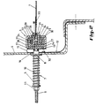
La figure 1 est une vue en élévation, avec brisures partielles, d'un dispositif suivant une première forme de réalisation de l'invention.Figure 1 is an elevational view, partially broken, of a device according to a first embodiment of the invention.
La figure 2 est, à plus grande échelle, une coupe suivant la ligne II-II de la figure 1.Figure 2 is, on a larger scale, a section along line II-II of Figure 1.
La figure 3 est une représentation schématique d'une coupe horizontale de cette même forme de réalisation, montrant la position du dispositif sous l'action d'une force horizontale appliquée sur le rideau.Figure 3 is a schematic representation of a horizontal section of this same embodiment, showing the position of the device under the action of a horizontal force applied to the curtain.
La figure 4 est une coupe transversale, analogue à celle de la figure 2, d'une deuxième forme de réalisation du dispositif suivant l'invention.Figure 4 is a cross section, similar to that of Figure 2, of a second embodiment of the device according to the invention.
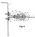
La figure 5 est également une coupe transversale analogue à celle de la figure 2 d'une troisième forme de réalisation du dispositif suivant l'invention.Figure 5 is also a cross section similar to that of Figure 2 of a third embodiment of the device according to the invention.
Dans les différentes figures, les mêmes chiffres de référence se rapportent aux mêmes éléments ou à des éléments analogues.In the different figures, the same reference numbers refer to the same or similar elements.
La forme de réalisation du dispositif de fermeture suivant l'invention, tel que representée aux figures à 3, comprend un rideau 1 pouvant s'enrouler autour d'un axe d'enroulement (non représente) et est p.e. destiné à la fermeture d'une baie, telle qu'une entrée de garage, d'atelier, de hangar, et également comme cloison de séparation d'un local, ou encore au recouvrement d'une piscine, d'un silo, etc.The embodiment of the closure device according to the invention, as shown in the figures to 3, comprises a
Ce rideau 1 présente des bords latéraux fléxibles 2, qui font saillie par rapport au plan du rideau et qui sont maintenus à glissement dans des chemins de guidage 3, prévus latéralement de part et d'autre de la baie à obturer p.e.This
Ce dispositif est essentiellement caractérisé par le fait que les chemins de guidage 3 sont montés sur un support 4, délimitant latéralement la baie, d'une manière élastique et/ou à pivotement autour d'un axe sensiblement parallèle à l'axe longitudinal de ces chemins de guidage, et ceci de manière telle que les bords latéraux 2 du rideau puissent continuer à être maintenus dans ces chemins de guidage lors d'un déplacement de ces derniers par rapport au support 4. En fait, c'est l'ensemble des parties du chemin de guidage qui maintiennent le bord du rideau qui est monté élastiquement et/ou à pivotement sur le support 4. Des moyens pourraient toutefois être prévus pour permettre le dégagement de ces bords latéraux 2 de leurs chemins de guidage lorsque la force de traction exercée par le rideau sur ces derniers dépasse une certaine valeur. Ceci est le cas lorsque les chemins de guidage présentent une certaine élasticité pour pouvoir s'ouvrir lorsqu'une certaine traction est exercée sur le rideau. Une autre possibilité est que certaines parties des chemins de guidage mêmes seraient montées à rotation par rapport à d'autres parties de ceux-ci et pourraient s'ouvrir et libérer ainsi les bords latéraux du rideau lorsque ce dernier est sollicité avec une certaine force. Une telle possibilité est décrite et représentée dans EP-A- 0405093. En fait, d'une façon générale, il s'agit, suivant l'invention, de chemins de guidage qui sont montés élastiquement et/ou à rotation par leur base sur un support fixe 4, les parties de ces derniers, destinées au maintien et guidage proprement dits, n'étant donc pas concernées.This device is essentially characterized in that the
Plus particulièrement, dans cette forme de réalisation spécifique du dispositif de fermeture suivant l'invention, les chemins de guidage 3 sont montés par l'intermédiaire de moyens élastiques, formes de ressorts hélicoïdaux 5, sur le support 4, de manière à pouvoir subir ainsi un déplacement dans la direction du rideau 1 lorsqu'une force, illustrée par la flèche 6 sur la figure 3, est appliquée sur celui-ci.More particularly, in this specific embodiment of the closure device according to the invention, the
Les chemins de guidage 3 sont agencés sur des tiges 7 s'étendant verticalement par rapport à l'axe longitudinal de ces derniers et montés avec un certain jeu dans des trous 8 ménagés dans la paroi du support 4, ce dernier étant, dans cette forme de réalisation, constitué d'un caisson métallique.The
Les ressorts hélicoïdaux 5 sont enfilés sur les tiges 7 à l'intérieur du caisson, en s'appuyant sur la paroi intérieure de ce dernier, du côté opposé de sa paroi sur laquelle est monté le chemin de guidage 3.The
Les tiges précitées 7 présentent une extrémité libre filetée 9 et sont montées chacune coaxialement dans un manchon 10 passant avec un certain jeu à travers les trous 8 ménagés dans le caisson de support 4, ce manchon étant immobilisé par rapport au chemin de guidage 3 par un écrou 11 vissé sur l'extrémité libre filetée 9 des tiges 7. Ainsi, les ressorts 5, qui sont enfilés sur le manchon 10, sont maintenus avec une certaine compression entre l'écrou 11 et la face intérieure de la paroi du caisson de support sur laquelle le chemin de guidage 3 est monté. De cette façon, les ressorts exercent une certaine traction sur le chemin de guidage 3 suivant une direction perpendiculaire à l'axe longitudinal de ce dernier.The
Afin d'assurer l'étanchéité entre le caisson de support 4 et le chemin de guidage 3, indépendamment de la distance qui les sépare les uns des autres, une bande souple d'étanchéité 12, par exemple réalisée en caoutchouc ou en plastique, est prévue entre le chemin de guidage 3 et le caisson de support 4.In order to seal between the support box 4 and the
Un des bords longitudinaux latéraux 13 de la bande d'étanchéité 12 présente des orifices qui sont traversés par les tiges 7. Ces dernières sont fixées a des distances régulières les unes par rapport aux autres sur le dos 14 des chemins de guidage 3, comme montré clairement à la figure 1. Ce bord 13 est maintenu contre le dos 14 du chemin de guidage 3 par l'intermédiaire de l'extrémité libre des manchons 10 dirigée vers ce dos, qui s'applique autour des orifices précités contre ce bord 13.One of the lateral longitudinal edges 13 of the
De plus, afin de permettre à la bande d'étanchéité de suivre les variations de l'écartement entre le chemin de guidage 3 et le caisson de support 4 sur lequel il est monte, la bande d'étanchéité 12 forme une boucle 15 entre le chemin de guidage 3 et le caisson de support 4. Ainsi, les tiges 7 traversent librement la branche 16 de la boucle 15 située du côte du caisson de support 4, de manière à ce que celle-ci puisse se déplacer librement sur le manchon 10 enfilé sur la tige 7. L'autre branche 17 présente le bord libre 13 et est fixée contre le dos 14 du chemin de guidage par l'extrémité libre du manchon 10, comme déjà décrit ci-dessus.In addition, in order to allow the sealing strip to follow the variations in the spacing between the
Dans la forme de réalisation particulière du dispositif de fermeture suivant l'invention, illustrée par les figures 1 à 3, les bords latéraux saillants 2 du rideau 1 sont formés par une succession de petits blocs juxtaposés identiques 2', réalisés de préférence en une matière plastique dure, situés dans le prolongement les uns des autres et à proximité les uns des autres, en étant reliés d'une manière flexible entre eux, par exemple comme les blochets d'une fermeture à glissière connue en soi. En fait, ces blochets peuvent être le plus près possible les uns des autres pour autant que les bords latéraux 2 restent suffisamment flexibles pour permettre l'enroulement du rideau autour d'un axe.In the particular embodiment of the closure device according to the invention, illustrated by FIGS. 1 to 3, the projecting
Toujours dans cette forme de réalisation particulière du dispositif de fermeture suivant l'invention, les chemins de guidage 3 présentent chacun deux rebords longitudinaux 18 et 19 situés de part et d'autre du rideau 1 et dirigés l'un vers l'autre suivant une direction sensiblement perpendiculaire au rideau. Ainsi, ces chemins de guidage 3 entourent le bord saillant 2 du rideau 1.Still in this particular embodiment of the closure device according to the invention, the
Ces deux rebords longitudinaux 18 et 19, qui retiennent donc le bord saillant 2 du rideau 1 dans les chemins de guidage, font partie de deux profilés séparés en une matière quelque peu élastique 20 et 21, qui présentent chacun une section transversale ayant une allure sensiblement en forme de Z. Une des deux ailes de ces profilés 20 et 21 forme le rebord longitudinal précité, respectivement 18 et 19, l'autre aile 22, respectivement 23, formant la base de ces profilés, qui est maintenue dans un profilé métallique rigide en U 24, dont les ailes présentent également des rebords 25 et 26 dirigés l'un vers l'autre. Les deux profilés en Z 20 et 21 sont maintenus dans le profilé en U 24 par une tige intercalaire 27 serrée dans ce dernier entre les bases de ces deux profilés 20 et 21 et une tige intercalaire 31 de part et d'autre de ces profilés et l'aile voisine du profilé en U. Ce dernier est alors, à son tour, maintenu dans un profile de support 28, également en U, dont les ailes présentent des rebords orientés l'un vers l'autre. Des barrettes 29, présentant une section en L et réalisées de préférence également en une matière relativement élastique, par exemple de la même nature que celle des profilés en Z 20 et 21, sont engagées dans des joints prévus entre les rebords 30 du profilé de support 28 et les profiles en Z pour s'appuyer latéralement contre ces derniers et ainsi contrôler leur flexibilité latérale.These two
Le fait que les profilés en Z 20 et 21 qui maintiennent les bords saillants 2 du rideau 1 présentent une certaine élasticité permet à ces bords de se dégager au chemin de guidage à lorsqu'une certaine force est appliquée sur le plan du rideau 1.The fact that the Z-
Des contacts 32 peuvent par exemple être agencés entre le chemin de guidage 3 et le support 4 pour permettre de détecter le moment où le bord saillant 2 du rideau 1 se serait dégagé du chemin de guidage et/ou que la force 6 exercée sur le rideau 1 dépasse une limite déterminée. Ces contacts 32 sont alors de préférence branchés dans un circuit d'alarme pour, par exemple, mettre hors service et bloquer le rideau dans son mouvement d'enroulement ou de déroulement, ou simplement pour mettre en action un appareil d'avertissement. Ces contacts pourraient également être prévus à l'intérieur du caisson et coopérer avec les tiges 7.
Dans une autre forme de réalisation de l'invention, des moyens peuvent avantageusement être prévus pour intercepter la force 6 agissant sur le rideau au moment ou celui-ci atteint une certaine limite, sans que le bord saillant 2 se dégage de ses chemins de guidage 3. Ainsi, le bord saillant 2 pourrait par exemple être fixé au rideau par des moyens de faible résistance s'étendant entre le rideau et ses bords saillants 2. Ces moyens pourraient par exemple être formés par une bride et des goupilles présentant une résistance calculée de sorte que ces goupilles puissent casser dès que la force 6 atteint une limite prédéterminée. On pourrait également prévoir entre le bord saillant 2 et le plan même du rideau une zone de faible résistance qui puisse céder au moment où la force précitée agissant sur le plan du rideau atteint un certain niveau qui soit inférieur à la force nécessaire pour dégager le bord saillant 2 du son chemin de guidage.In another embodiment of the invention, means can advantageously be provided for intercepting the
La forme de réalisation du dispositif suivant l'invention montrée à la figure 4 diffère essentiellement par rapport à celle de la figure 2 par le fait que les moyens élastiques sont constitués par des éléments en mousse sensiblement élastique 5, telle que de la mousse de polyuréthane ou de latex. Ces éléments 5 s'étendent sur toute la longueur du chemin de guidage 3 et permettent ainsi d'assurer l'étanchéité entre ce dernier et le support 4 sur lequel il est monté, sans qu'il soit nécessaire d'y prévoir une bande supplémentaire d'étanchéité, comme dans la précédente forme de réalisation. Ces éléments en mousse 5 sont constitués de barrettes de section rectangulaire et sont agencés dans un profile en U 34 fixé par soudure contre la face extérieure du caisson de support 4. Les ailes latérales de ce profilé 34 présentent des rebords 35 dirigés l'un vers l'autre contre lesquels est appliquée une des faces 38 des éléments en mousse 5.The embodiment of the device according to the invention shown in Figure 4 differs essentially from that of Figure 2 in that the elastic means are constituted by elements of substantially
Par ailleurs, les profilés en Z 20 et 21 sont fixés sur toute leur longueur d'une manière démontable entre deux plaques identiques 37, dont un des bords longitudinaux présente l'allure d'un crochet (25) et maintien les profilés 20 et 21 en place, le bord longitudinal opposé étant pourvu de pattes d'appui 36 s'appliquant contre la face 39 des éléments en mousse 5 opposée à celle s'appuyant contre les rebords 35 du profilé 34.Furthermore, the
Un plat intercalaire 27 s'étend entre les deux plaques 35 et les bases des profilés 20 et 21 et détermine la distance séparant ces derniers les uns des autres. De plus, les bords en forme de crochet 25 sont appliqués d'une manière élastiquement réglable contre les profilés 20 et 21 afin de pouvoir contrôler ainsi la force agissant par ces derniers sur les bords 2 du rideau 1, particulièrement la force qui est nécessaire pour dégager les bords 2 du chemin de guidage 3.An
A cet effet, les bords libres 40 des crochets 25 sont légèrement inclinés en s'appliquant élastiquement contre les profilés 20 et 21 et un boulon traversant les plaques 37 et le plat intercalaire 31 permet, au moyen d'un écrou 42 vissé sur ce boulon 41, de régler la pression exercée par ces bords libres 40 sur les profilés 20 et 21.For this purpose, the
La forme de réalisation du dispositif suivant l'invention telle que représentée à la figure 5 se distingue essentiellement par rapport à celle de la figure 4 par le fait que les moyens élastiques sont constitués par deux bandes en matière élastique 5, telle que du caoutchouc ou un élastomère plastique, qui sont soumises à une force de traction, alors que, dans la forme de réalisation suivant la figure 4, les barrettes de mousse 5 sont soumises à une force de compression. Un des bords latéraux de ces bandes 5 présente un bourrelet 43 maintenu dans une goutiére 44 des plaques 37 appliquées contre le plat intercalaire 31. L'autre bord latéral de ces bandes est replié contre la face extérieure du caisson de support 4 et est maintenu contre ce dernier par des boulons 45 régulièrement espacés. Ces bandes 5 qui s'étendent sur toute la longueur du chemin de guidage 3 forment donc en même temps un joint d'étanchéité entre ce dernier et le caisson de support 4.The embodiment of the device according to the invention as shown in FIG. 5 differs essentially from that of FIG. 4 by the fact that the elastic means consist of two bands of
Il peut également être important de prévoir des moyens d'arrêt permettant de limiter le déplacement des chemins de guidage 3 dans la direction du rideau 1 lorsqu'une force 6 est exercée sur ce dernier.It may also be important to provide stop means making it possible to limit the displacement of the guide tracks 3 in the direction of the
Dans le cas de la forme de réalisation suivant la figure 2, l'arrêt est automatiquement obtenu au moment ou toutes les spires du ressort sont appliquées l'un contre l'autre. Si les moyens élastiques sont formés d'éléments en mousse, l'arrêt est obtenu lorsque ces éléments sont entièrement comprimes. Si on fait usage de bandes élastiques, qui sont donc soumises à une traction, il pourrait être important d'incorporer dans ces dernières une armature permettant de limiter l'allongement de la bande suivant la direction de la traction.In the case of the embodiment according to Figure 2, the stop is automatically obtained when all the turns of the spring are applied against each other. If the elastic means are formed of foam elements, the stop is obtained when these elements are fully compressed. If elastic bands are used, which are therefore subjected to traction, it could be important to incorporate therein an armature making it possible to limit the elongation of the band in the direction of traction.
Un des avantages des formes de réalisation suivant les figures 4 et 5 est que toutes les accessoires des chemins de guidage 3 se situent à l'extérieur du support 4, de sorte que ce dernier pourrait, le cas échéant, être constitué d'une paroi pleine, telle qu'une colonne en béton.One of the advantages of the embodiments according to FIGS. 4 and 5 is that all the accessories of the guide tracks 3 are located outside the support 4, so that the latter could, if necessary, consist of a wall full, such as a concrete column.
Grâce au fait que les chemins de guidage 3 sont montés sur leur support 4 par l'intermédiaire de moyens élastiques, pratiquement aucun ajustement n'est nécessaire sur chantier, le montage complet des chemins de guidage sur leurs supports correspondants pouvant se réaliser entièrement en usine.Thanks to the fact that the guide tracks 3 are mounted on their support 4 by means of elastic means, practically no adjustment is necessary on site, the complete mounting of the guide tracks on their corresponding supports being able to be carried out entirely in the factory. .
Par ailleurs, par la présence des moyens élastiques, le rideau est constamment sous une tension horizontale contrôlée et des dilatations ou rétrécissements du rideau qui pourraient se produire suite à des fluctuations de température seront automatiquement compensés par les moyens élastiques. Ceci sera également le cas pour des variations de distance entre les chemins de guidage de part et d'autre du rideau, p.e. si ces derniers ne sont pas parfaitement parallèles.Furthermore, by the presence of the elastic means, the curtain is constantly under a controlled horizontal tension and expansions or shrinkages of the curtain which could occur following temperature fluctuations will be automatically compensated by the elastic means. This will also be the case for variations of distance between the guide paths on either side of the curtain, eg if the latter are not perfectly parallel.
Grâce au fait que les chemins de guidage peuvent pivoter autour d'un axe parallèle à leur axe longitudinal, la traction exercée par le rideau 1, par l'intermédiaire des bords 2, sera toujours repartie symétriquement sur les deux profilés 20 et 21, notamment sur les deux rebords respectivement 18 et 19 de ces derniers, et ceci toujours suivant une direction sensiblement parallèle à l'âme 34 de ces deux profilés 20 et 21.Thanks to the fact that the guide tracks can pivot around an axis parallel to their longitudinal axis, the traction exerted by the
Ainsi, il sera parfaitement possible de déterminer d'une manière assez rigoureuse les caractéristiques physiques auxquelles les profilés 20 et 21 doivent répondre pour que le bord 2 puisse se dégager de ses chemins de guidage 3 à partir d'une force déterminée appliquée sur le rideau 1. De plus, grâce au fait que la force de frottement du bord 2 sera repartie symétriquement sur les deux profilés 18 et 19, l'usure tant du bord que des profilés sera uniforme et réduite à un strict minimum, ce qui augmentera sensiblement la longévité de ces éléments.Thus, it will be perfectly possible to determine in a fairly rigorous manner the physical characteristics to which the
Il doit être entendu que l'invention n'est nullement limitée à la forme de réalisation particulière décrite ci-dessus et représentée aux figures du dispositif suivant l'invention et que bien des variantes peuvent être envisagées sans sortir de cette invention comme définie dans les revendications ; c'est ainsi que, pour certaines applications ou types de dispositif, le chemin de guidage 3 pourrait être monté sur le support 4 par l'intermédiaire d'une charnière ou d'une série de charnières successives, dont l'axe de rotation est parallèle à l'axe de ce chemin de guidage.It should be understood that the invention is in no way limited to the particular embodiment described above and shown in the figures of the device according to the invention and that many variants can be envisaged without departing from this invention as defined in the claims; this is how, for certain applications or types of device, the
Par ailleurs, dans d'autres cas, ces chemins de guidage pourraient être montés sur leurs supports de manière à ne pouvoir subir qu'une translation suivant le plan du rideau en position fermée, les moyens élastiques ne permettraient alors pas le pivotement du chemin de guidage.By the way, in other cases, these paths guide could be mounted on their supports so as to be able to undergo only a translation along the plane of the curtain in the closed position, the elastic means would then not allow the pivoting of the guide path.
Il va toutefois de soi qu'une préférence prononcée est donnée à un système dans lequel le chemin de guidage peut simultanément subir un pivotement et une translation élastique.It goes without saying, however, that a pronounced preference is given to a system in which the guide path can simultaneously undergo pivoting and elastic translation.
Dans encore d'autres cas, le bord 2 du rideau 1 pourrait être prévu de moyens de guidage espacés, tels que des galets ou patins s'étendant à une certaine distance l'un de l'autre sur le bord du rideau. Il ne s'agirait donc pas d'un bord saillant sensiblement continu.In still other cases, the
Enfin, suivant une forme de réalisation particulière de l'invention le rideau 1 est constitué d'une bâche et présente au moins une zone sensiblement élastique 50, formée par exemple par une bande en une matière élastique montrée schématiquement sur la figure 1, s'étendant sur toute la longueur du rideau 1, suivant la direction de ses bords latéraux. Cette zone 50 peut en principe être située à n'importe quel endroit du rideau, mais pour de raisons de symétrie, p.e. elle se trouvera de préférence à proximité de chacun de ses bords latéraux 2 ou éventuellement au milieu. On pourrait toutefois également prévoir une seule zone élastique à proximité d'un des deux bords latéraux 2. Dans une variante, tout le rideau pourrait être réalisé en une matière sensiblement élastique. Les chemins de guidage 3 pourraient être montés à pivotement ou être fixé sur le support 4. On pourrait même combiner ces dernières formes de réalisation avec celles où les chemins de guidage 3 sont montés d'une manière élastique sur le support 4.Finally, according to a particular embodiment of the invention, the
Dans le cadre de la présente invention, le rideau est de préférence constitué d'une bâche continue entièrement souple, en opposition aux rideaux qui comprennent à des distances régulières des barres horizontales légèrement flexibles ou non, qui assurent le guidage latéral du rideau.In the context of the present invention, the curtain preferably consists of a fully flexible continuous sheet, in contrast to the curtains which comprise at regular distances horizontal bars which are slightly flexible or not, which provide lateral guidance of the curtain.
Claims (27)
- Closing, separating or covering device comprising a blind presenting flexible lateral edges held in guide tracks, characterized in that said guide tracks (3) are mounted on a support (4) in an elastic manner and/or pivoting about an axis essentially parallel to their longitudinal axis, said lateral edges (2) continuing to be held in the guide tracks (3) in case of a rotation and/or a translation of said guide tracks with respect to the support (4).
- Device according to claim 1, characterized in that the guide tracks (3) are mounted through elastic means (5) on the support (4) in such a way that they can undergo a displacement in the direction of the blind (1) when a force (6) is exerted on the latter.
- Device according to claim 2, characterized in that the elastic means (5) are arranged so as to exert a constant traction on the lateral edges (2) of the blind (1).
- Device according to either of claims 2 or 3, characterized in that the guide tracks (3) are arranged on rods (7) extending essentially vertically to the longitudinal axis of said guide tracks (3) and mounted with a certain amount of play in holes (8) in a wall of the support (4), where said elastic means comprise a helical spring (5) slid over said rod (7) on the side of said wall (4) opposite the guide track (3), resting against said wall (4).
- Device according to claim 4, characterized in that said rod (7) has a threaded free end (9) and that said rod (7) is mounted coaxially in a sleeve (10) which extends with a certain amount of play through the hole (8) in the wall of the support (4), and is immobilized with respect to the guide track (3) by a nut (11) screwed onto the threaded free end (9) of the rod (7), where said spring (5) is held between said nut (11) and the surface of the wall of the support (4) facing the latter.
- Device according to any of claims 2 to 5, characterized in that a flexible strip (12), for example to provide sealing against the wind, is fitted between the guide track (3) and the support (4) on which said guide track is mounted.
- Device according to claim 6, characterized in that one of the longitudinal edges (13) of the sealing strip (12) has holes through which said rods (7) run, said rods being fixed at certain distances from each other on the back (14) of the guide tracks (3), where said edge (13) is held close to said back (14) through the free end of the sleeves (10) pointing towards said back (14) and pressing around said orifices against said longitudinal edge (13) of the sealing strip (12).
- Device according to either of claims 6 and 7, characterized in that the sealing strip (12) is folded to form a loop (15) between the guide track (3) and the support (4) on which said guide track (3) is mounted, where said rods (7) carrying said guide track (3) pass through the end branch (16) of the loop (15) nearest the support (4), and where the free edge (13) of the other branch (17) is fixed against the back of the guide track (3).
- Device according to either of claims 2 or 3, characterized in that the elastic means (3) comprise essentially elastic foam elements.
- Device according to either of claims 2 or 3, characterized in that the elastic means (5) comprise strips made of an essentially elastic material.
- Device according to any of claims 1 to 10, characterized in that the lateral edges (2) of the blind (1) project from its surface and preferably comprise a succession of small, identical, essentially rigid juxtaposed blocks (20) placed one beside the other and connected to each other in a flexible manner.
- Device according to any of claims 1 to 11, characterized in that the guide tracks (3) have two longitudinal rims (18,19) extending on either side of the blind (1) and pointing towards each other so as to at least partially enclose the edge (2) of the blind (1) which is held in the guide tracks (3).
- Device according to claim 12, characterized in that the guide tracks (3) comprise at least one section (20,21) with said longitudinal rims (18,19) at least partially enclosing the edge (2) of the blind (1), where said section (20,21) is made of slightly elastic material, so that when a certain force (6) is applied to the surface of the blind (1), said edge (2) is able to free itself from the guide track.
- Device according to claim 13, characterized in that each guide track (3) comprises two separate sections (20,21) made of a slightly elastic material and extending at a certain distance from each other while being held at their base (22, 23) by an essentially rigid U-section (24) whose flanges also have rims (25,26) pointing towards each other.
- Device according to claim 14, characterized in that the two said sections (20,21) have a cross section essentially in the form of a Z, where one of the two flanges of said sections (20,21) forms said longitudinal rim (18,19) and the other flange (22,23) forms said base, said two Z-sections being held in the U-section by a spacer bar (27) clamped in said U-section between two said Z-profiles (20,21), and by a spacer bar (31) between each of these sections and the neighbouring flange of the U-section (24).
- Device according to any of claims 13 to 15, characterized in that the sections (20,21) are held between two plates (37) fixed opposite each other in a detachable manner and extending in the longitudinal direction of the guide tracks (3), one of the longitudinal edges of said plates (37) being shaped like a hook (25) and engaging the sections (20,21), while the other edge engages the elastic means (5).
- Device according to claim 16, characterized in that a spacer flat (27) extends between the two plates (37) and the sections (20,21).
- Device according to any of claims 9 and 11 to 17, characterized in that the foam elements (5) are arranged in a U-section (34) fixed to the support (4), where the side flanges of said profile (34) have rims (35) facing towards each other, against which one of the surfaces (38) of the foam elements (5) is applied, the guide tracks (3) having pressure elements (36) which cooperate on the side (39) of the foam elements (5) opposite the side resting against said rims (35).
- Device according to claim 18, characterized in that the said other longitudinal edge of the plate (37) has a flange (36) extending along the face (38) of the foam elements (5), said flange in this way forming said pressure element.
- Device according to claim 16, characterized in that, in the case where the elastic means comprise strips (5) made of an elastic material, one of the lateral edges (39) of said strips is held by the above-mentioned other lateral edge of the plate (37), while the other lateral edge (40) of the elastic strip (5) is fixed to the support (4).
- Device according to any of claims 16 to 20, characterized in that the hook-shaped edges (25) of the plates (37) are applied in an adjustable elastic manner against the sections (20,21) so as to control the force acting through said sections on the edges (2) of the blind (1).
- Device according to any of claims 2 to 21, characterized by stop means limiting the displacement of the guide tracks (3) in the direction of the blind when a force (6) is exerted on it.
- Device according to any of claims 1 to 22, characterized in that there is at least one contact (32) making it possible to detect the moment when the edge (2) of the blind (1) comes free of the guide track (3) and/or the force acting on said blind (1) exceeds a certain limit, where said contact (32) is connected to an alarm circuit.
- Closing, separating or covering device comprising a blind (1) having flexible lateral edges (2) held in guide tracks (3), characterized in that said blind (1) has a narrow zone (33) of low strength, located between the projecting edge (2) and the surface of the blind itself (1), extending over the whole length of said edge (2), preferably close to it, where said zone (33) yields as soon as the force acting on the surface of the blind (1) reaches a certain limit, which is less than the force necessary to free the edge (2) from the guide tracks (3).
- Closing, separating or covering device comprising a blind (1) having flexible lateral edges (2) held in guide tracks (3), characterized in that said blind (1) has at least one essentially elastic zone (50) extending over the whole length of the blind (1) in the direction of its lateral edges (2).
- Device according to claim 25, characterized in that the blind comprises a tarpaulin with an uninterrupted, essentially elastic zone (50) extending close to each of the lateral edges of the blind (1)
- Device according to claim 25, characterised in that the blind (1) is made of an essentially elastic material.
Applications Claiming Priority (3)
| Application Number | Priority Date | Filing Date | Title |
|---|---|---|---|
| BE9100499A BE1004897A3 (en) | 1991-05-24 | 1991-05-24 | Closure device, or separation of coverage. |
| BE9100499 | 1991-05-24 | ||
| PCT/BE1992/000017 WO1992020895A1 (en) | 1991-05-24 | 1992-05-15 | Closing, separating or covering device |
Publications (2)
| Publication Number | Publication Date |
|---|---|
| EP0587586A1 EP0587586A1 (en) | 1994-03-23 |
| EP0587586B1 true EP0587586B1 (en) | 1997-03-19 |
Family
ID=3885521
Family Applications (1)
| Application Number | Title | Priority Date | Filing Date |
|---|---|---|---|
| EP92909384A Expired - Lifetime EP0587586B1 (en) | 1991-05-24 | 1992-05-15 | Closing, separating or covering device |
Country Status (11)
| Country | Link |
|---|---|
| US (1) | US5526865A (en) |
| EP (1) | EP0587586B1 (en) |
| AT (1) | ATE150520T1 (en) |
| AU (1) | AU1676292A (en) |
| BE (1) | BE1004897A3 (en) |
| CA (1) | CA2109823C (en) |
| DE (1) | DE69218429T2 (en) |
| DK (1) | DK0587586T3 (en) |
| ES (1) | ES2101844T3 (en) |
| GR (1) | GR3023787T3 (en) |
| WO (1) | WO1992020895A1 (en) |
Families Citing this family (63)
| Publication number | Priority date | Publication date | Assignee | Title |
|---|---|---|---|---|
| US5579820A (en) | 1994-11-10 | 1996-12-03 | Lepage; Robert | Roll-up door for vehicle shelters |
| US6089305A (en) * | 1995-02-10 | 2000-07-18 | Rite-Hite Holding Corporation | Curtain guiding assembly for a soft edge door with a selectively tensioned leading edge |
| US5638883A (en) * | 1995-02-10 | 1997-06-17 | Rite-Hite Corporation | Breakaway guide assembly for a roller door |
| US5944086A (en) * | 1995-02-10 | 1999-08-31 | Rite-Hite Holding Corporation | Curtain bottom tensioning assembly |
| MX9705789A (en) * | 1995-02-10 | 1997-10-31 | Rite Hite Corp | Curtain bottom tensioning assembly. |
| US6698490B2 (en) | 1996-05-28 | 2004-03-02 | Rite-Hite Holding Corporation | Release mechanism for industrial doors |
| US5887385A (en) * | 1996-05-28 | 1999-03-30 | Rite-Hite Holding Corporation | Release mechanism for industrial doors |
| FR2756866B1 (en) * | 1996-12-10 | 1999-01-22 | Kodak Pathe | FLEXIBLE CURTAIN CLOSURE DEVICE FOR LIGHT-SHIELDED ROOM |
| FR2762642B1 (en) | 1997-04-23 | 1999-07-30 | Bernard Simon | GUIDE DEVICE FOR A FLEXIBLE CURTAIN DOOR |
| DE29906582U1 (en) * | 1999-04-14 | 2000-09-21 | Langenbach Guido | Crash protection device |
| FR2804159B1 (en) * | 2000-01-20 | 2002-09-06 | Bernard Simon | SEMI-RIGID BLADES FOR FLEXIBLE CURTAIN HANDLING DOOR |
| EP1191184A1 (en) | 2000-09-25 | 2002-03-27 | Dynaco International | Shutter device for closing an opening |
| EP1233138A1 (en) * | 2001-02-16 | 2002-08-21 | Dynaco International | Device with a flexible shutter |
| BE1014544A3 (en) * | 2001-12-14 | 2003-12-02 | Dynaco Internat | Shutter device with guidance paths. |
| DE20200310U1 (en) * | 2002-01-10 | 2003-05-22 | Detenhoff Reiner | Roller shutter has sensor and lock stop operated by spring link if pushed up |
| BE1014712A3 (en) * | 2002-03-20 | 2004-03-02 | Dynaco Internat | SHUTTER DEVICE WITH FLEXIBLE SIDE EDGES |
| US6722416B2 (en) | 2002-04-03 | 2004-04-20 | Overhead Door Corporation | Flexible curtain rollup door with combination stiffening struts and windlocks |
| US6942003B2 (en) * | 2003-07-25 | 2005-09-13 | Service Door Industries Limited | Roll-up door curtain and guides and bottom bar therefor |
| CN1580479B (en) * | 2003-08-12 | 2010-06-23 | 三和控股株式会社 | Sheet roller shutter door |
| FR2863646B1 (en) * | 2003-12-11 | 2006-02-24 | Nergeco Sa | IMPROVED CURTAIN DOOR BY ROLLER WITH IMPROVED SIDE SEAL |
| DE102004033982A1 (en) * | 2004-07-14 | 2006-02-02 | Arvinmeritor Gmbh | Guide rail for a roller blind of a sunroof system |
| US20080093037A1 (en) * | 2004-12-10 | 2008-04-24 | Bernard Kraeutler | Door Provided With a Curtain Which is Raisable by Winding and Has an Improved Lateral Tightness |
| EP1840321A1 (en) * | 2006-03-29 | 2007-10-03 | Dynaco International S.A. | Device for guiding a roll-type closure |
| DE102006017538B4 (en) * | 2006-04-13 | 2010-08-12 | Webasto Ag | Roller blind arrangement for a vehicle |
| US7748431B2 (en) | 2006-06-05 | 2010-07-06 | Rite-Hite Holding Corporation | Track and guide system for a door |
| US8037921B2 (en) * | 2006-06-05 | 2011-10-18 | Rite-Hite Holding Corporation | Track and guide system for a door |
| US20070277943A1 (en) * | 2006-06-05 | 2007-12-06 | Rite-Hite Holding Corporation | Track and guide system for a door |
| EP1953018B1 (en) * | 2007-01-31 | 2010-03-17 | ArvinMeritor GmbH | Guiding system for a roller blind of a sliding roof system |
| US8113265B2 (en) * | 2009-03-02 | 2012-02-14 | Rite-Hite Holding Corporation | Washdown door |
| US8408274B2 (en) | 2009-10-26 | 2013-04-02 | Rajiva Dwarka | Architectural apparatus and method |
| TWI499713B (en) * | 2009-11-06 | 2015-09-11 | Komatsu Denki Sangyo Kabushiki Kaisha | Sheet guide of sheet shutter |
| US20120012260A1 (en) * | 2010-07-16 | 2012-01-19 | Leonard Elinson | Retractable shade assembly with adjustable side guides |
| TW201241296A (en) * | 2011-04-06 | 2012-10-16 | Komatsu Denki Sangyo Kabushiki Kaisha | Sheet shutter |
| US9347258B2 (en) * | 2011-05-11 | 2016-05-24 | Rajiva A. Dwarka | Retractable curtain panel with track guide |
| US20130068400A1 (en) * | 2011-05-11 | 2013-03-21 | Rajiva A. Dwarka | Retractable curtain panel with track guide |
| US20160319593A1 (en) * | 2011-05-11 | 2016-11-03 | Rajiva A. Dwarka | Retractable curtain panel with track guide |
| US20170009524A1 (en) * | 2011-05-11 | 2017-01-12 | Rajiva A. Dwarka | Retractable curtain panel and enhanced stiffeners |
| JP5647683B2 (en) * | 2011-06-24 | 2015-01-07 | 林口工業株式会社 | Roll screen device |
| US9057219B1 (en) | 2011-08-30 | 2015-06-16 | Newell Window Furnishings, Inc. | Window covering with integrated side track |
| US20130255893A1 (en) * | 2012-01-10 | 2013-10-03 | Jochen Stöbich | Fire and Smoke Protection System |
| US9249621B2 (en) | 2012-01-18 | 2016-02-02 | Rajiva A. Dwarka | Coil brush curtain assembly |
| DE102013204032A1 (en) * | 2013-03-08 | 2014-09-11 | HELLA Sonnen- und Wetterschutztechnik GmbH | Sound-technical separating element with sealing function |
| US9222304B2 (en) * | 2013-04-12 | 2015-12-29 | Rite-Hite Holding Corporation | Systems and methods to retain and refeed door curtains |
| US9493984B2 (en) | 2013-04-12 | 2016-11-15 | Rite-Hite Holding Corporation | Systems and methods to retain and refeed door curtains |
| KR20150069262A (en) * | 2013-12-13 | 2015-06-23 | 현대자동차주식회사 | Apparatus for preventing droop of blind for panorama sunroof |
| JP6228504B2 (en) * | 2014-04-11 | 2017-11-08 | フクビ化学工業株式会社 | Screen device and manufacturing method thereof |
| JP6309832B2 (en) * | 2014-06-17 | 2018-04-11 | セイキ住工株式会社 | Retractable screen device |
| EP2987667B1 (en) | 2014-08-18 | 2019-10-09 | Inalfa Roof Systems Group B.V. | Guide and sunshade assembly provided therewith |
| EP2987668B1 (en) | 2014-08-18 | 2019-04-24 | Inalfa Roof Systems Group B.V. | Sunshade assembly |
| JP6453624B2 (en) * | 2014-11-25 | 2019-01-16 | 文化シヤッター株式会社 | Shutter guide rail structure |
| CN104527382B (en) * | 2014-12-30 | 2017-03-08 | 上海万超汽车天窗有限公司 | Panoramic roofs roof assembly |
| EP3247857B1 (en) | 2015-01-21 | 2018-12-26 | Entrematic Belgium Nv | Wind safe door |
| EP3098376A1 (en) * | 2015-05-29 | 2016-11-30 | Plastex SA | Upright for a shading system, removable flange of the upright and corresponding coupling means |
| ES2580553B1 (en) * | 2016-02-09 | 2017-02-13 | Iaso, S.A. | GUIDE BODY FOR LAMINARY SLIDING ELEMENTS |
| NL2016892B1 (en) * | 2016-06-03 | 2018-01-12 | Metaal En Kunststoffen Ind Snelder B V | SCREEN DEVICE FOR A WAREHOUSE |
| EP3478918A1 (en) | 2016-06-29 | 2019-05-08 | Assa Abloy Entrance Systems AB | Safety door with ultrasonic detectors |
| US11421474B2 (en) * | 2016-08-03 | 2022-08-23 | Defender Screens International, Llc | Self-tensioning magnetic tracks and track assemblies |
| US9719292B1 (en) | 2016-08-03 | 2017-08-01 | Defender Screens International LLC | Self-tensioning magnetic tracks and track assemblies |
| US20190048658A1 (en) * | 2017-08-09 | 2019-02-14 | Professional Blinds System Inc. | Construction assembly for installing a roller blind or the like |
| MX2021012081A (en) | 2019-04-03 | 2022-01-31 | Michael Heissenberg | Retractable screen with tensioning track. |
| ES1239394Y (en) * | 2019-10-10 | 2020-06-22 | Producciones Mitjavila Sau | ROLLABLE CANVAS GUIDE STRUCTURE |
| IT202100029276A1 (en) * | 2021-11-19 | 2023-05-19 | Sgheiz Solutions | QUICK-ROLL DOOR GUIDE |
| US20230250692A1 (en) * | 2022-02-10 | 2023-08-10 | Kolar L. Seshasai | High wind tolerant track assembly for a motorized retractable screen |
Family Cites Families (12)
| Publication number | Priority date | Publication date | Assignee | Title |
|---|---|---|---|---|
| US1632742A (en) * | 1925-05-13 | 1927-06-14 | Ernest E Minard | Shade guide |
| US1736432A (en) * | 1928-01-16 | 1929-11-19 | Rolscreen Co | Plaster-channel installation for screen guides |
| US1840454A (en) * | 1931-08-20 | 1932-01-12 | Francis M Kennedy | Roller screen |
| CH192088A (en) * | 1936-12-23 | 1937-07-31 | Jeker Werner | Guiding device for blinds, blinds, tarpaulin roofs on cars or tents, car radiator covers, etc. |
| DE8525625U1 (en) * | 1985-09-09 | 1985-10-24 | Schieffer GmbH & Co KG, 4780 Lippstadt | rolling gate |
| GB8624735D0 (en) * | 1986-10-15 | 1986-11-19 | Clark Door Ltd | Roller door assemblies |
| BE906022A (en) * | 1986-12-23 | 1987-04-16 | Coenraets B J | SHUTTER DEVICE. |
| FR2624190B1 (en) * | 1987-12-02 | 1990-05-11 | Nergeco Sa | REINFORCEMENT AND GUIDANCE BAR FOR A FLEXIBLE CURTAIN WITH VERTICAL LIFTING DOOR |
| FR2656648A2 (en) * | 1989-05-19 | 1991-07-05 | Nergeco Sa | Roller shutter door which can be raised and is reinforced by horizontal reinforcing bars |
| EP0405093A3 (en) * | 1989-06-27 | 1991-07-17 | Rytec Corporation | Apparatus configured for maintaining a barrier in a position against a trans-barrier force less than a predetermined magnitude |
| US5176194A (en) * | 1989-08-08 | 1993-01-05 | Metaco Co., Ltd. | Roller screen unit |
| US5131450A (en) * | 1990-06-08 | 1992-07-21 | Dale Lichy | Closure assembly for structural members |
-
1991
- 1991-05-24 BE BE9100499A patent/BE1004897A3/en not_active IP Right Cessation
-
1992
- 1992-05-15 AT AT92909384T patent/ATE150520T1/en not_active IP Right Cessation
- 1992-05-15 DK DK92909384.7T patent/DK0587586T3/en active
- 1992-05-15 AU AU16762/92A patent/AU1676292A/en not_active Abandoned
- 1992-05-15 CA CA002109823A patent/CA2109823C/en not_active Expired - Lifetime
- 1992-05-15 WO PCT/BE1992/000017 patent/WO1992020895A1/en active IP Right Grant
- 1992-05-15 DE DE69218429T patent/DE69218429T2/en not_active Expired - Lifetime
- 1992-05-15 EP EP92909384A patent/EP0587586B1/en not_active Expired - Lifetime
- 1992-05-15 US US08/142,371 patent/US5526865A/en not_active Expired - Lifetime
- 1992-05-15 ES ES92909384T patent/ES2101844T3/en not_active Expired - Lifetime
-
1997
- 1997-06-18 GR GR970401427T patent/GR3023787T3/en unknown
Also Published As
| Publication number | Publication date |
|---|---|
| BE1004897A3 (en) | 1993-02-16 |
| DK0587586T3 (en) | 1997-09-15 |
| WO1992020895A1 (en) | 1992-11-26 |
| ES2101844T3 (en) | 1997-07-16 |
| DE69218429T2 (en) | 1997-08-28 |
| CA2109823C (en) | 2005-12-27 |
| DE69218429D1 (en) | 1997-04-24 |
| AU1676292A (en) | 1992-12-30 |
| ATE150520T1 (en) | 1997-04-15 |
| CA2109823A1 (en) | 1992-11-26 |
| GR3023787T3 (en) | 1997-09-30 |
| US5526865A (en) | 1996-06-18 |
| EP0587586A1 (en) | 1994-03-23 |
Similar Documents
| Publication | Publication Date | Title |
|---|---|---|
| EP0587586B1 (en) | Closing, separating or covering device | |
| EP0272733B1 (en) | Shutter device | |
| BE1016275A3 (en) | Dipositif a component of a drum roll around. | |
| EP2122102B1 (en) | Device with a flexible shutter | |
| CA2647291A1 (en) | Closure device with a curtain having flexible lateral edges | |
| BE1014506A3 (en) | Device with re-introduction component element. | |
| EP0500499B1 (en) | Venetian blind | |
| FR2656601A1 (en) | APPARATUS FOR SIMULTANEOUSLY DISPENSING AND CUTTING TAPES OF ROLLED MATERIALS. | |
| FR2921405A1 (en) | Blind device for e.g. window, has semi-closed slot-shaped thickening provided at exterior sides of blind, where thickening is arranged in guiding section to retain and guide blind in blind guides | |
| FR3056615A1 (en) | DEVICE FOR RECOVERING A SWIMMING POOL | |
| EP0426524B1 (en) | Fastening device for a curtain rod | |
| EP0546971B1 (en) | Invisible junction device, suitable in particular for tight fabrics | |
| FR2753743A1 (en) | Wind resistant blind | |
| FR2765617A1 (en) | ARTICULATION DEVICE, PARTICULARLY FOR PLATES AND A MOVING CURTAIN IN THE FORM OF PLATES JOINED BY SUCH DEVICES | |
| EP0994219A1 (en) | Overflowed barrage with pivoted panel | |
| BE1005266A5 (en) | Device for fixing a glass on a support. | |
| BE1017124A6 (en) | Rideau flexible device. | |
| FR2844541A1 (en) | DEVICE FOR SEALING A SLIDING DOOR | |
| CH645430A5 (en) | Automatic locking device for a roller blind | |
| FR2664324A1 (en) | Device for driving a roller shutter in a horizontal or slightly sloping position | |
| FR2487422A1 (en) | Automatic lock for roller blind - has pin-joined curved strap to secure head of blind to roller and to stop upward movement of deployed blind | |
| FR2538026A1 (en) | Improved gate with a metal framework and generally a wooden cladding | |
| FR2582712A1 (en) | Locking device for a metal shutter and the shutter obtained | |
| FR2508092A1 (en) | Window frame for vehicle or building - has resilient size automatically holding pane at required angle w.r.t. surrounding frame | |
| FR2514400A1 (en) | Over glazing for door or window leaf - has multiple fixing wedges spaced along leaf frame with cover plates |
Legal Events
| Date | Code | Title | Description |
|---|---|---|---|
| PUAI | Public reference made under article 153(3) epc to a published international application that has entered the european phase |
Free format text: ORIGINAL CODE: 0009012 |
|
| 17P | Request for examination filed |
Effective date: 19931118 |
|
| AK | Designated contracting states |
Kind code of ref document: A1 Designated state(s): AT BE CH DE DK ES FR GB GR IT LI LU NL SE |
|
| 17Q | First examination report despatched |
Effective date: 19950829 |
|
| GRAG | Despatch of communication of intention to grant |
Free format text: ORIGINAL CODE: EPIDOS AGRA |
|
| GRAH | Despatch of communication of intention to grant a patent |
Free format text: ORIGINAL CODE: EPIDOS IGRA |
|
| GRAH | Despatch of communication of intention to grant a patent |
Free format text: ORIGINAL CODE: EPIDOS IGRA |
|
| GRAA | (expected) grant |
Free format text: ORIGINAL CODE: 0009210 |
|
| AK | Designated contracting states |
Kind code of ref document: B1 Designated state(s): AT BE CH DE DK ES FR GB GR IT LI LU NL SE |
|
| REF | Corresponds to: |
Ref document number: 150520 Country of ref document: AT Date of ref document: 19970415 Kind code of ref document: T |
|
| REG | Reference to a national code |
Ref country code: CH Ref legal event code: EP |
|
| REF | Corresponds to: |
Ref document number: 69218429 Country of ref document: DE Date of ref document: 19970424 |
|
| ITF | It: translation for a ep patent filed |
Owner name: BARZANO' E ZANARDO MILANO S.P.A. |
|
| REG | Reference to a national code |
Ref country code: CH Ref legal event code: NV Representative=s name: ISLER & PEDRAZZINI AG |
|
| GBT | Gb: translation of ep patent filed (gb section 77(6)(a)/1977) |
Effective date: 19970512 |
|
| RAP2 | Party data changed (patent owner data changed or rights of a patent transferred) |
Owner name: DYNACO INTERNATIONAL |
|
| REG | Reference to a national code |
Ref country code: ES Ref legal event code: FG2A Ref document number: 2101844 Country of ref document: ES Kind code of ref document: T3 |
|
| REG | Reference to a national code |
Ref country code: GR Ref legal event code: FG4A Free format text: 3023787 |
|
| NLT2 | Nl: modifications (of names), taken from the european patent patent bulletin |
Owner name: DYNACO INTERNATIONAL |
|
| REG | Reference to a national code |
Ref country code: DK Ref legal event code: T3 |
|
| PLBE | No opposition filed within time limit |
Free format text: ORIGINAL CODE: 0009261 |
|
| STAA | Information on the status of an ep patent application or granted ep patent |
Free format text: STATUS: NO OPPOSITION FILED WITHIN TIME LIMIT |
|
| 26N | No opposition filed | ||
| REG | Reference to a national code |
Ref country code: GB Ref legal event code: IF02 |
|
| REG | Reference to a national code |
Ref country code: CH Ref legal event code: PCAR Free format text: ISLER & PEDRAZZINI AG;POSTFACH 1772;8027 ZUERICH (CH) |
|
| PGFP | Annual fee paid to national office [announced via postgrant information from national office to epo] |
Ref country code: LU Payment date: 20080516 Year of fee payment: 17 Ref country code: CH Payment date: 20080530 Year of fee payment: 17 |
|
| PGFP | Annual fee paid to national office [announced via postgrant information from national office to epo] |
Ref country code: AT Payment date: 20080531 Year of fee payment: 17 |
|
| PGFP | Annual fee paid to national office [announced via postgrant information from national office to epo] |
Ref country code: SE Payment date: 20080509 Year of fee payment: 17 |
|
| PGFP | Annual fee paid to national office [announced via postgrant information from national office to epo] |
Ref country code: GR Payment date: 20080530 Year of fee payment: 17 |
|
| PGRI | Patent reinstated in contracting state [announced from national office to epo] |
Ref country code: IT Effective date: 20090801 |
|
| REG | Reference to a national code |
Ref country code: CH Ref legal event code: PL |
|
| PG25 | Lapsed in a contracting state [announced via postgrant information from national office to epo] |
Ref country code: LI Free format text: LAPSE BECAUSE OF NON-PAYMENT OF DUE FEES Effective date: 20090531 Ref country code: CH Free format text: LAPSE BECAUSE OF NON-PAYMENT OF DUE FEES Effective date: 20090531 Ref country code: AT Free format text: LAPSE BECAUSE OF NON-PAYMENT OF DUE FEES Effective date: 20090515 |
|
| PG25 | Lapsed in a contracting state [announced via postgrant information from national office to epo] |
Ref country code: GR Free format text: LAPSE BECAUSE OF NON-PAYMENT OF DUE FEES Effective date: 20091202 |
|
| PGRI | Patent reinstated in contracting state [announced from national office to epo] |
Ref country code: IT Effective date: 20090801 |
|
| PG25 | Lapsed in a contracting state [announced via postgrant information from national office to epo] |
Ref country code: LU Free format text: LAPSE BECAUSE OF NON-PAYMENT OF DUE FEES Effective date: 20090515 |
|
| PG25 | Lapsed in a contracting state [announced via postgrant information from national office to epo] |
Ref country code: SE Free format text: LAPSE BECAUSE OF NON-PAYMENT OF DUE FEES Effective date: 20090516 |
|
| PGFP | Annual fee paid to national office [announced via postgrant information from national office to epo] |
Ref country code: FR Payment date: 20110607 Year of fee payment: 20 Ref country code: ES Payment date: 20110628 Year of fee payment: 20 |
|
| PGRI | Patent reinstated in contracting state [announced from national office to epo] |
Ref country code: IT Effective date: 20110616 |
|
| PGFP | Annual fee paid to national office [announced via postgrant information from national office to epo] |
Ref country code: NL Payment date: 20110531 Year of fee payment: 20 Ref country code: GB Payment date: 20110525 Year of fee payment: 20 Ref country code: DK Payment date: 20110525 Year of fee payment: 20 |
|
| REG | Reference to a national code |
Ref country code: GB Ref legal event code: 732E Free format text: REGISTERED BETWEEN 20110804 AND 20110810 |
|
| PGFP | Annual fee paid to national office [announced via postgrant information from national office to epo] |
Ref country code: BE Payment date: 20110630 Year of fee payment: 20 Ref country code: IT Payment date: 20110527 Year of fee payment: 20 |
|
| PGFP | Annual fee paid to national office [announced via postgrant information from national office to epo] |
Ref country code: DE Payment date: 20110629 Year of fee payment: 20 |
|
| REG | Reference to a national code |
Ref country code: NL Ref legal event code: TD Effective date: 20111209 |
|
| REG | Reference to a national code |
Ref country code: FR Ref legal event code: TP Owner name: DYNACO EUROPE NV, BE Effective date: 20111212 |
|
| REG | Reference to a national code |
Ref country code: ES Ref legal event code: PC2A Owner name: DYNACO EUROPE N.V. Effective date: 20120126 |
|
| REG | Reference to a national code |
Ref country code: DE Ref legal event code: R082 Ref document number: 69218429 Country of ref document: DE Representative=s name: GRUENECKER, KINKELDEY, STOCKMAIR & SCHWANHAEUS, DE |
|
| REG | Reference to a national code |
Ref country code: DE Ref legal event code: R082 Ref document number: 69218429 Country of ref document: DE Representative=s name: GRUENECKER PATENT- UND RECHTSANWAELTE PARTG MB, DE Effective date: 20120312 Ref country code: DE Ref legal event code: R082 Ref document number: 69218429 Country of ref document: DE Representative=s name: GRUENECKER, KINKELDEY, STOCKMAIR & SCHWANHAEUS, DE Effective date: 20120312 Ref country code: DE Ref legal event code: R081 Ref document number: 69218429 Country of ref document: DE Owner name: DYNACO EUROPE NV, BE Free format text: FORMER OWNER: DYNACO INTERNATIONAL, BRUESSEL/BRUXELLES, BE Effective date: 20120312 |
|
| REG | Reference to a national code |
Ref country code: DE Ref legal event code: R071 Ref document number: 69218429 Country of ref document: DE |
|
| REG | Reference to a national code |
Ref country code: DE Ref legal event code: R071 Ref document number: 69218429 Country of ref document: DE |
|
| REG | Reference to a national code |
Ref country code: NL Ref legal event code: V4 Effective date: 20120515 |
|
| BE20 | Be: patent expired |
Owner name: DYNACO EUROPE N.V. Effective date: 20120515 |
|
| REG | Reference to a national code |
Ref country code: DK Ref legal event code: EUP |
|
| REG | Reference to a national code |
Ref country code: GB Ref legal event code: PE20 Expiry date: 20120514 |
|
| PG25 | Lapsed in a contracting state [announced via postgrant information from national office to epo] |
Ref country code: DE Free format text: LAPSE BECAUSE OF EXPIRATION OF PROTECTION Effective date: 20120516 |
|
| PG25 | Lapsed in a contracting state [announced via postgrant information from national office to epo] |
Ref country code: GB Free format text: LAPSE BECAUSE OF EXPIRATION OF PROTECTION Effective date: 20120514 |
|
| REG | Reference to a national code |
Ref country code: ES Ref legal event code: FD2A Effective date: 20130711 |
|
| PG25 | Lapsed in a contracting state [announced via postgrant information from national office to epo] |
Ref country code: ES Free format text: LAPSE BECAUSE OF EXPIRATION OF PROTECTION Effective date: 20120516 |