EP0586934A1 - Seitenkanalgebläse mit reduzierter Geräuschentwicklung - Google Patents
Seitenkanalgebläse mit reduzierter Geräuschentwicklung Download PDFInfo
- Publication number
- EP0586934A1 EP0586934A1 EP93113160A EP93113160A EP0586934A1 EP 0586934 A1 EP0586934 A1 EP 0586934A1 EP 93113160 A EP93113160 A EP 93113160A EP 93113160 A EP93113160 A EP 93113160A EP 0586934 A1 EP0586934 A1 EP 0586934A1
- Authority
- EP
- European Patent Office
- Prior art keywords
- gas
- interference
- blower
- channel
- elements
- Prior art date
- Legal status (The legal status is an assumption and is not a legal conclusion. Google has not performed a legal analysis and makes no representation as to the accuracy of the status listed.)
- Granted
Links
Images
Classifications
-
- F—MECHANICAL ENGINEERING; LIGHTING; HEATING; WEAPONS; BLASTING
- F04—POSITIVE - DISPLACEMENT MACHINES FOR LIQUIDS; PUMPS FOR LIQUIDS OR ELASTIC FLUIDS
- F04D—NON-POSITIVE-DISPLACEMENT PUMPS
- F04D29/00—Details, component parts, or accessories
- F04D29/66—Combating cavitation, whirls, noise, vibration or the like; Balancing
- F04D29/661—Combating cavitation, whirls, noise, vibration or the like; Balancing especially adapted for elastic fluid pumps
- F04D29/667—Combating cavitation, whirls, noise, vibration or the like; Balancing especially adapted for elastic fluid pumps by influencing the flow pattern, e.g. suppression of turbulence
-
- F—MECHANICAL ENGINEERING; LIGHTING; HEATING; WEAPONS; BLASTING
- F04—POSITIVE - DISPLACEMENT MACHINES FOR LIQUIDS; PUMPS FOR LIQUIDS OR ELASTIC FLUIDS
- F04D—NON-POSITIVE-DISPLACEMENT PUMPS
- F04D23/00—Other rotary non-positive-displacement pumps
- F04D23/008—Regenerative pumps
-
- F—MECHANICAL ENGINEERING; LIGHTING; HEATING; WEAPONS; BLASTING
- F04—POSITIVE - DISPLACEMENT MACHINES FOR LIQUIDS; PUMPS FOR LIQUIDS OR ELASTIC FLUIDS
- F04D—NON-POSITIVE-DISPLACEMENT PUMPS
- F04D29/00—Details, component parts, or accessories
- F04D29/08—Sealings
- F04D29/16—Sealings between pressure and suction sides
- F04D29/161—Sealings between pressure and suction sides especially adapted for elastic fluid pumps
Definitions
- the invention relates to a device for reducing the noise in a fan provided with a gas inlet duct, a gas outlet duct and a gas propulsion device, in particular a side duct blower for the combustion air supply in a heater.
- the noise development in heaters which are provided with a fan for supplying combustion air to the combustion chamber of the heater is largely determined by flow noises resulting from the combustion air flow in the fan.
- this noise development proves to be disruptive because of the additional heating device which is usually located in the vicinity of the vehicle occupants due to the limited vehicle dimensions.
- the object of the invention is therefore to create a device which enables the operation of a blower with reduced noise.
- the device according to the invention has, at least in the region of the opening cross section of the gas outlet channel and / or the gas inlet channel, an interfering device which influences the flow behavior of the gas flow accelerated by the gas propulsion device.
- the acceleration of the gas flow induces pressure waves in the fan, in particular in the area of the opening cross section of the gas outlet channel and the gas inlet channel, the propagation of which leads to the known, disadvantageous noise development in the fan.
- the disturbance device induces flow resistances in the accelerated gas flow, which have an adverse effect on the pressure wave propagation. In this way, the generation of large pressure waves, which lead to a corresponding increase in the noise level during operation of the fan, is prevented. Instead, there are smaller pressure waves, which lead to a correspondingly lower noise level when spreading in the fan housing. As a result, the noise generated during operation of the fan is significantly reduced by the interference device.
- the interference device is arranged in an edge region adjacent to the gas outlet channel and / or the gas inlet channel of a housing separating surface parallel to the plane of rotation of the gas propulsion device.
- Side channel blowers consist of at least two housing parts, between which a gas propulsion device, for example in the form of an impeller, is arranged. Both the gas inlet through the gas inlet channel and the gas outlet through the gas outlet channel take place on one side of the impeller, the gas flowing in a channel which is guided parallel to the plane of rotation of the gas propulsion device.
- the arrangement of the interference device in the edge region of the housing partition has proven to be particularly effective for reducing the noise, since the housing partition is located directly adjacent to the gas propulsion device and therefore the maximum gas velocities, induced by the gas propulsion device, occur in this region.
- the effect of the individual jamming elements which disturbs the accelerated gas flow and thus the propagation of pressure waves, can be increased in that the jamming elements have different sizes and / or shapes.
- the interference elements are at different distances from one another. In this way, the formation of interference between the individual interference elements is achieved, which further increases the interference effect of the individual interference elements.
- the interference elements provided in the housing separating surface can also be arranged such that they have a greater dimension parallel to the housing separating surface than perpendicular to it. This also enables a further improvement in the interference effect.
- the interference elements designed as material recesses can consist of notches with an approximately V-shaped cross section.
- the notch-shaped design of the interfering elements can be implemented, for example by file blows introduced into the blower housing after the casting process represents a particularly simple possibility of realizing interfering elements.
- Interfering elements formed from material recesses also offer the advantage that their manufacture already during the manufacture of the blower housing which is generally produced by the casting process, for example by inserting appropriate ones Molded parts can be made in the mold.
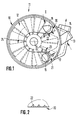
- FIG. 1 shows a housing part 10 of a side channel blower 11 with a side channel 12 formed therein, as well as a gas inlet channel 13 and a gas outlet channel 14.
- the impeller 15 serves as a gas propulsion device, by means of which gas sucked in through the gas inlet duct 13 is accelerated in the side duct 12 and is output through the gas outlet duct 14.
- the gas outlet channel 14 is with this heater or the combustion chamber connected to the heater.
- a suction line (not shown here) can be connected to the gas inlet channel 13.
- the interference devices 20, 21 shown by way of example in terms of their arrangement and configuration in FIG. 1 each have individual interference elements 22, 23, each of which is designed as a notch with a V-shaped cross section ( FIG. 2 ).
- Fig. 2 shows in a view pivoted by 90 ° compared to the representation in Fig. 1, the V-shaped cross section of the interfering elements 22, wherein it can be seen that the greatest cross-sectional depth of the interfering elements 22 lies in a plane perpendicular to the separating surface 17 and the cross-sectional depth with increasing expansion of the interference elements 22 in the separating surface 17 decreases continuously, that is, the notches run out slowly.
- a directed interference effect of the interference elements 22 is produced by the design of the notches inclined in the separating surface 17 and tapering in this.
- the interfering elements 22 and 23 of the interfering devices 20, 21 are arranged approximately radially around the opening cross sections 18, 19 of the gas inlet channel 13 and the gas outlet channel 14. It is also possible that the individual interference elements 22 and 23 of the interference device 20 and 21 are aligned substantially parallel to each other. Contrary to the illustration in FIG. 1 , the interference elements 22 and 23 can of course also be of the same size. Furthermore, it can prove to be advantageous to arrange interfering elements 22, 23 not only in the area of the opening cross sections 18, 19 or in the area of one of these two opening cross sections, but interfering elements 22, 23 individually or in groups distributed over the entire edge area of the separating surface 17 from the opening cross section 18 to provide the opening cross-section 19.
- the interfering elements 22, 23 do not necessarily have to be limited to the area of the separating surface 17, but can instead or additionally also directly at the opening cross section 18 or 19 of the gas inlet channel 13 or the gas outlet channel 14 or on the inside on the outer peripheral edge 24 of the side channel 12 be arranged to achieve the advantageous effects made possible by the invention.
Landscapes
- Engineering & Computer Science (AREA)
- Mechanical Engineering (AREA)
- General Engineering & Computer Science (AREA)
- Structures Of Non-Positive Displacement Pumps (AREA)
- Details Of Fluid Heaters (AREA)
- Air Supply (AREA)
- Motor Or Generator Cooling System (AREA)
- Chimneys And Flues (AREA)
Abstract
Description
- Die Erfindung betrifft eine Vorrichtung zur Reduzierung der Geräuschentwicklung bei einem mit einem Gaseintrittskanal, einem Gasaustrittskanal und einer Gasvortriebseinrichtung versehenen Gebläse, insbesondere einem Seitenkanalgebläse für die Verbrennungsluftzuführung bei einem Heizgerät.
- Die Geräuschentwicklung bei Heizgeräten, die mit einem Gebläse zur Zuführung von Verbrennungsluft in die Brennkammer des Heizgerätes versehen sind, wird maßgeblich bestimmt durch von der Verbrennungsluftströmung im Gebläse herrührenden Strömungsgeräuschen. Insbesondere bei Kleinheizgeräten, wie sie beispielsweise als motorunabhängige Zusatzheizeinrichtung in Kraftfahrzeugen Verwendung finden, erweist sich diese Geräuschentwicklung wegen der in der Regel aufgrund der begrenzten Fahrzeugabmessungen in der Nähe der Fahrzeuginsassen befindlichen Zusatzheizeinrichtung als störend.
- Der Erfindung liegt daher die Aufgabe zugrunde, eine Vorrichtung zu schaffen, die den Betrieb eines Gebläses bei reduzierter Geräuschentwicklung ermöglicht.
- Diese Aufgabe wird durch die Merkmale des Anspruchs 1 gelöst.
- Die erfindungsgemäße Vorrichtung weist zumindest im Bereich des Öffnungsquerschnitts des Gasaustrittskanals und/oder des Gaseintrittskanals eine Störeinrichtung auf, die die durch die Gasvortriebseinrichtung beschleunigte Gasströmung in ihrem Strömungsverhalten beeinflußt. Durch die Beschleunigung der Gasströmung werden im Gebläse, insbesondere im Bereich des Öffnungsquerschnitts des Gasaustrittskanals und des Gaseintrittskanals, Druckwellen induziert, deren Ausbreitung zu der bekannten, nachteiligen Geräuschentwicklung im Gebläse führt. Die Störeinrichtung induziert Strömungswiderstände in der beschleunigten Gasströmung, die sich behindernd auf die Druckwellenausbreitung auswirken. Auf diese Art und Weise wird das Entstehen großer Druckwellen, die zu einem entsprechenden Ansteigen des Geräuschpegels beim Betrieb des Gebläses führen, verhindert. Statt dessen entstehen kleinere Druckwellen, die bei Ausbreitung im Gebläsegehäuse zu entsprechend geringerer Geräuschentwicklung führen. Demzufolge wird durch die Störeinrichtung die Geräuschentwicklung beim Betrieb des Gebläses entscheidend reduziert.
- Bei einem als Seitenkanalgebläse ausgebildeten Gebläse erweist es sich als besonders vorteilhaft, wenn die Störeinrichtung in einem dem Gasaustrittskanal und/oder dem Gaseintrittskanal benachbarten Randbereich einer zur Rotationsebene der Gasvortriebseinrichtung parallelen Gehäusetrennfläche angeordnet ist. Seitenkanalgebläse bestehen aus zumindest zwei Gehäuseteilen, zwischen denen eine Gasvortriebseinrichtung, etwa in Form eines Flügelrads, angeordnet ist. Sowohl der Gaszutritt durch den Gaseintrittskanal als auch der Gasaustritt durch den Gasaustrittskanal erfolgt auf einer Seite des Flügelrades, wobei das Gas in einem Kanal, der parallel zur Rotationsebene der Gasvortriebseinrichtung geführt ist, strömt. Die Anordnung der Störeinrichtung im Randbereich der Gehäusetrennfläche erweist sich zur Reduzierung der Geräuschentwicklung als besonders effektiv, da sich die Gehäusetrennfläche unmittelbar benachbart der Gasvortriebseinrichtung befindet und daher in diesem Bereich die maximalen Gasgeschwindigkeiten, induziert durch die Gasvortriebseinrichtung, auftreten.
- Bei einer aus mehreren Störelementen bestehend Störeinrichtung kann die die beschleunigte Gasströmung und damit die Ausbreitung von Druckwellen störende Wirkung der einzelnen Störelemente dadurch gesteigert werden, daß die Störelemente unterschiedliche Größen und/oder Formen aufweisen. Das gleiche gilt, wenn die Störelemente unterschiedliche Abstände voneinander aufweisen. Auf diese Art und Weise wird die Ausbildung von Interferenzen zwischen den einzelnen Störelementen erreicht, die den Störeffekt der einzelnen Störelemente an sich noch verstärkt.
- Bei einem als Seitenkanalgebläse ausgebildeten Gebläse können die in der Gehäusetrennfläche vorgesehenen Störelemente darüber hinaus noch so angeordnet sein, daß sie parallel zur Gehäusetrennfläche eine größere Ausdehnung als senkrecht dazu aufweisen. Auch hierdurch wird eine weitere Verbesserung der Störwirkung ermöglicht.
- Die als Materialausnehmungen ausgebildeten Störelemente können aus Kerben mit einem etwa V-förmigen Querschnitt bestehen. Die kerbenförmige Ausbildung der Störelemente, beispielsweise realisierbar durch nach dem Gießvorgang in das Gebläsegehäuse eingebrachte Feilenhiebe, stellt eine besonders einfache Möglichkeit der Realisierung von Störelementen dar. Aus Materialausnehmungen gebildete Störelemente bieten auch den Vorteil, daß ihre Herstellung bereits bei der Fertigung der in der Regel im Gießverfahren hergestellten Gebläsegehäuse, etwa durch Einlegen entsprechender Formteile in die Gießform, erfolgen kann.
- Nachfolgend wird eine bevorzugte Ausführungsform der erfindungsgemäßen Vorrichtung anhand der Zeichnungen näher erläutert. Es zeigen:
- Fig. 1
- einen Gehäuseteil eines Seitenkanalgebläses mit Seitenkanal und in diesen einmündenden Gasaustrittskanal und Gaseintrittskanal mit einer sowohl im Bereich des Gaseintrittskanals als auch im Bereich des Gasaustrittskanals vorgesehenen Störeinrichtung;
- Fig. 2
- einen Gehäuseausschnitt mit Darstellung der Störeinrichtung im Bereich des Gaseintrittskanals entsprechend einer durch den Pfeil II in Fig. 1 gekennzeichneten Ansicht.
- Fig. 1 zeigt einen Gehäuseteil 10 eines Seitenkanalgebläses 11 mit einem darin ausgebildeten Seitenkanal 12, sowie einem Gaseintrittskanal 13 und einem Gasaustrittskanal 14.
- Mit durchbrochenem Linienverlauf dargestellt in Fig. 1 ist ein Flügelrad 15, das zwischen dem Gehäuseteil 10 und einem in Fig. 1 nicht dargestellten weiteren Gehäuseteil, der mit dem Gehäuseteil 10 zusammen das Gebläsegehäuse bildet, auf einer Drehachse 16 drehend aufgenommen ist. Das Flügelrad 15 dient als Gasvortriebseinrichtung, mittels der durch den Gaseintrittskanal 13 angesaugtes Gas im Seitenkanal 12 beschleunigt und durch den Gasaustrittskanal 14 ausgegeben wird. Bei Verwendung des Seitenkanalgebläses 11 zur Verbrennungsluftzuführung in eine Brennkammer eines hier nicht dargestellten Heizgerätes ist der Gasaustrittskanal 14 mit diesem Heizgerät bzw. der Brennkammer des Heizgeräts verbunden. An den Gaseintrittskanal 13 kann eine hier nicht dargestellte Ansaugleitung angeschlossen werden.
- Eine Trennfläche 17 des Gehäuseteils 10, die unmittelbar benachbart dem Flügelrad 15 parallel zu diesem angeordnet ist, ist in ihren den Öffnungsquerschnitten 18, 19 des Gaseintrittskanal 13 bzw. des Gasaustrittskanals 14 benachbarten Randbereichen mit einer Störeinrichtung 20 bzw. 21 versehen. Die in Fig. 1 bezüglich ihrer Anordnung und Ausgestaltung beispielhaft dargestellten Störeinrichtungen 20, 21 weisen jeweils einzelne Störelemente 22, 23 auf, die jeweils als Kerben mit V-förmigem Querschnitt (Fig. 2) ausgebildet sind.
- Fig. 2 zeigt in einer gegenüber der Darstellung in Fig. 1 um 90° geschwenkten Ansicht den V-förmigen Querschnitt der Störelemente 22, wobei ersichtlich ist, daß die größte Querschnittstiefe der Störelemente 22 in einer Ebene senkrecht zur Trennfläche 17 liegt und die Querschnittstiefe mit zunehmender Ausdehnung der Störelemente 22 in die Trennfläche 17 stetig abnimmt, die Kerben also langsam auslaufen.
- Neben der V-förmigen Ausbildung des Kerbenquerschnitts wird durch die in der Trennfläche 17 geneigte und in dieser auslaufenden Ausbildung der Kerben eine gerichtete Störwirkung der Störelemente 22 erzeugt.
- In Fig. 1 sind die Störelemente 22 bzw. 23 der Störeinrichtungen 20, 21 etwa strahlenförmig um die Öffnungsquerschnitte 18, 19 des Gaseintrittskanals 13 bzw. des Gasaustrittskanals 14 angeordnet. Genauso ist es möglich, daß die einzelnen Störelemente 22 bzw. 23 der Störeinrichtung 20 bzw. 21 im wesentlichen parallel zueinander ausgerichtet sind. Natürlich können die Störelemente 22 bzw. 23 entgegen der Darstellung in Fig. 1 auch hinsichtlich ihrer Größe gleich ausgebildet sein. Weiterhin kann es sich als vorteilhaft erweisen, Störelemente 22, 23 nicht nur im Bereich der Öffnungsquerschnitte 18, 19 oder im Bereich eines dieser beiden Öffnungsquerschnitte anzuordnen, sondern Störelemente 22, 23 einzeln oder in Gruppen zusammengefaßt verteilt über den gesamten Randbereich der Trennfläche 17 vom Öffnungsquerschnitt 18 bis zum Öffnungsquerschnitt 19 vorzusehen. Auch müssen die Störelemente 22, 23 nicht notwendigerweise auf den Bereich der Trennfläche 17 beschränkt sein, sondern können auch statt dessen oder zusätzlich unmittelbar am Öffnungsquerschnitt 18 bzw. 19 des Gaseintrittskanals 13 bzw. des Gasaustrittskanals 14 oder auch innenseitig am äußeren Umfangsrand 24 des Seitenkanals 12 angeordnet sein, um die mit der Erfindung ermöglichten vorteilhaften Effekte zu erzielen.
Claims (6)
- Vorrichtung zur Reduzierung der Geräuschentwicklung bei einem mit einem Gaseintrittskanal (13), einem Gasaustrittskanal (14) und einer Gasvortriebseinrichtung (15) versehenen Gebläse (11), insbesondere einem Seitenkanalgebläse für die Verbrennungsluftzuführung bei einem Heizgerät, dadurch gekennzeichnet,
daß zumindest im Bereich des Öffnungsquerschnitts (18,19) des Gaseintrittskanals (13) und/oder des Gasaustrittskanals (14) eine Einrichtung zur Induzierung eines Strömungswiderstandes (Störeinrichtung 20,21) angeordnet ist. - Vorrichtung nach Anspruch 1,
dadurch gekennzeichnet,
daß die Störeinrichtung (20,21) bei einem als Seitenkanalgebläse ausgebildeten Gebläse (11) zumindest in einem dem Gaseintrittskanal (13) und/oder dem Gasaustrittskanal (14) benachbarten Randbereich einer zur Rotationsebene der Gasvortriebseinrichtung (15) parallelen Gehäusetrennfläche (17) angeordnet ist. - Vorrichtung nach Anspruch 1 oder 2,
dadurch gekennzeichnet,
daß die Störeinrichtung (20,21) aus mehreren Störelementen (22,23) besteht, die zumindest zum Teil eine unterschiedliche Größe und/oder Form aufweisen. - Vorrichtung nach einem oder mehreren der vorangehenden Ansprüche,
dadurch gekennzeichnet,
daß die Störeinrichtung (20,21) aus mehreren Störelementen (22,23) besteht, die zumindest zum Teil unterschiedliche Abstände voneinander aufweisen. - Vorrichtung nach Anspruch 2, sowie einem oder mehreren der weiteren Ansprüche,
dadurch gekennzeichnet,
daß die die Störeinrichtung (20,21) bildenden Störelemente (22,23) in der Gehäusetrennfläche (17) eine größere Ausdehnung als senkrecht dazu aufweisen. - Vorrichtung nach einem oder mehreren der vorangehenden Ansprüche,
dadurch gekennzeichnet,
daß die Störelemente aus Materialausnehmungen mit einem vorzugsweise V-förmigen Querschnitt (Kerben 22,23) gebildet sind.
Applications Claiming Priority (2)
| Application Number | Priority Date | Filing Date | Title |
|---|---|---|---|
| DE4230014 | 1992-09-08 | ||
| DE4230014A DE4230014C1 (de) | 1992-09-08 | 1992-09-08 | Vorrichtung zur Reduzierung der Geräuschentwicklung bei Gebläsen |
Publications (2)
| Publication Number | Publication Date |
|---|---|
| EP0586934A1 true EP0586934A1 (de) | 1994-03-16 |
| EP0586934B1 EP0586934B1 (de) | 1996-11-06 |
Family
ID=6467510
Family Applications (1)
| Application Number | Title | Priority Date | Filing Date |
|---|---|---|---|
| EP93113160A Expired - Lifetime EP0586934B1 (de) | 1992-09-08 | 1993-08-17 | Seitenkanalgebläse mit reduzierter Geräuschentwicklung |
Country Status (5)
| Country | Link |
|---|---|
| EP (1) | EP0586934B1 (de) |
| JP (1) | JP3153058B2 (de) |
| AT (1) | ATE145039T1 (de) |
| DE (2) | DE4230014C1 (de) |
| ES (1) | ES2094979T3 (de) |
Cited By (6)
| Publication number | Priority date | Publication date | Assignee | Title |
|---|---|---|---|---|
| EP0718502A1 (de) * | 1994-12-23 | 1996-06-26 | Firma J. Eberspächer | Seitenkanalgebläse |
| EP0767308A1 (de) * | 1995-10-06 | 1997-04-09 | Siemens Aktiengesellschaft | Seitenkanalverdichter |
| EP1589229A1 (de) * | 2004-04-23 | 2005-10-26 | J. Eberspächer GmbH & Co. KG | Gebläse |
| WO2010052044A1 (de) * | 2008-11-06 | 2010-05-14 | Pierburg Gmbh | Seitenkanalgebläse, insbesondere sekundärluftgebläse für eine verbrennungskraftmaschine |
| WO2012041625A1 (de) * | 2010-09-29 | 2012-04-05 | Pierburg Gmbh | Seitenkanalgebläse, insbesondere sekundärluftgebläse für eine verbrennungskraftmaschine |
| WO2023236011A1 (zh) * | 2022-06-06 | 2023-12-14 | 广东德昌电机有限公司 | 侧流道泵 |
Families Citing this family (4)
| Publication number | Priority date | Publication date | Assignee | Title |
|---|---|---|---|---|
| DE19780570D2 (de) * | 1996-06-19 | 1999-05-27 | Eberspaecher J Gmbh & Co | Seitenkanalgebläse, insbesondere für die Verbrennungsluftzuführung bei einem Standheizgerät eines Kraftfahrzeugs |
| US6071071A (en) * | 1996-07-16 | 2000-06-06 | J. Eberspacher Gmbh & Co. | Side-channel fan, in particular for supplying combustion air in an independent heater of a motor vehicle |
| DE19638847C5 (de) * | 1996-09-21 | 2006-01-26 | J. Eberspächer GmbH & Co. KG | Seitenkanalgebläse, insbesondere für die Verbrennungsluftzuführung bei einem Standheizgerät eines Kraftfahrzeugs |
| DE102014226298A1 (de) * | 2014-12-17 | 2016-06-23 | Mahle International Gmbh | Gebläse |
Citations (3)
| Publication number | Priority date | Publication date | Assignee | Title |
|---|---|---|---|---|
| GB1402713A (en) * | 1971-06-30 | 1975-08-13 | Lintott Eng Ltd | Vortex compressor |
| US3951567A (en) * | 1971-12-18 | 1976-04-20 | Ulrich Rohs | Side channel compressor |
| FR2319792A1 (fr) * | 1975-07-30 | 1977-02-25 | British Gas Corp | Soufflante radiale |
Family Cites Families (8)
| Publication number | Priority date | Publication date | Assignee | Title |
|---|---|---|---|---|
| US2109742A (en) * | 1935-09-17 | 1938-03-01 | Atlas Heating & Ventilating Co | Blower |
| GB1361036A (en) * | 1971-11-05 | 1974-07-24 | Hansford R J | Gas turbine ducted fan propulsion unit |
| JPS5115210A (en) * | 1974-07-02 | 1976-02-06 | Rotoron Inc | Zatsuongenshono fuan |
| JPS5186815A (de) * | 1975-01-27 | 1976-07-29 | Fuji Electric Co Ltd | |
| JPS5272901A (en) * | 1975-12-15 | 1977-06-18 | Ebara Corp | Suction tank with vortex breaking wall for plural numbers of pumps use |
| JPS56135799A (en) * | 1980-03-26 | 1981-10-23 | Hitachi Ltd | Apparatus for alleviating vibration of shaft of centrifugal fluid machine |
| JPS62145737A (ja) * | 1985-12-20 | 1987-06-29 | Nec Corp | 低圧成形用封止金型 |
| EP0466983A1 (de) * | 1990-07-16 | 1992-01-22 | Crosslee Plc | Geräuschunterdrückung |
-
1992
- 1992-09-08 DE DE4230014A patent/DE4230014C1/de not_active Expired - Fee Related
-
1993
- 1993-08-17 EP EP93113160A patent/EP0586934B1/de not_active Expired - Lifetime
- 1993-08-17 ES ES93113160T patent/ES2094979T3/es not_active Expired - Lifetime
- 1993-08-17 AT AT93113160T patent/ATE145039T1/de not_active IP Right Cessation
- 1993-08-17 DE DE59304401T patent/DE59304401D1/de not_active Expired - Fee Related
- 1993-09-07 JP JP22170193A patent/JP3153058B2/ja not_active Expired - Fee Related
Patent Citations (3)
| Publication number | Priority date | Publication date | Assignee | Title |
|---|---|---|---|---|
| GB1402713A (en) * | 1971-06-30 | 1975-08-13 | Lintott Eng Ltd | Vortex compressor |
| US3951567A (en) * | 1971-12-18 | 1976-04-20 | Ulrich Rohs | Side channel compressor |
| FR2319792A1 (fr) * | 1975-07-30 | 1977-02-25 | British Gas Corp | Soufflante radiale |
Non-Patent Citations (1)
| Title |
|---|
| PATENT ABSTRACTS OF JAPAN vol. 6, no. 50 (M-120)(928) 3. April 1982 & JP-A-56 165 795 ( HITACHI ) 19. Dezember 1981 * |
Cited By (7)
| Publication number | Priority date | Publication date | Assignee | Title |
|---|---|---|---|---|
| EP0718502A1 (de) * | 1994-12-23 | 1996-06-26 | Firma J. Eberspächer | Seitenkanalgebläse |
| EP0767308A1 (de) * | 1995-10-06 | 1997-04-09 | Siemens Aktiengesellschaft | Seitenkanalverdichter |
| EP1589229A1 (de) * | 2004-04-23 | 2005-10-26 | J. Eberspächer GmbH & Co. KG | Gebläse |
| WO2010052044A1 (de) * | 2008-11-06 | 2010-05-14 | Pierburg Gmbh | Seitenkanalgebläse, insbesondere sekundärluftgebläse für eine verbrennungskraftmaschine |
| WO2012041625A1 (de) * | 2010-09-29 | 2012-04-05 | Pierburg Gmbh | Seitenkanalgebläse, insbesondere sekundärluftgebläse für eine verbrennungskraftmaschine |
| US9297276B2 (en) | 2010-09-29 | 2016-03-29 | Pierburg Gmbh | Side channel blower, in particular a secondary air blower for an internal combustion machine |
| WO2023236011A1 (zh) * | 2022-06-06 | 2023-12-14 | 广东德昌电机有限公司 | 侧流道泵 |
Also Published As
| Publication number | Publication date |
|---|---|
| ES2094979T3 (es) | 1997-02-01 |
| JPH06159298A (ja) | 1994-06-07 |
| DE4230014C1 (de) | 1994-03-24 |
| JP3153058B2 (ja) | 2001-04-03 |
| EP0586934B1 (de) | 1996-11-06 |
| DE59304401D1 (de) | 1996-12-12 |
| ATE145039T1 (de) | 1996-11-15 |
Similar Documents
| Publication | Publication Date | Title |
|---|---|---|
| DE2837543A1 (de) | Dunstabzugsvorrichtung | |
| DE3539604C1 (de) | Axialgeblaese | |
| DE4037442A1 (de) | Anordnung zur laermverminderung bei staubsaugern | |
| DE2849675A1 (de) | Kuehlanlage fuer brennkraftmaschinen, insbesondere in fahrzeugen | |
| EP0586934B1 (de) | Seitenkanalgebläse mit reduzierter Geräuschentwicklung | |
| DE10064264B4 (de) | Anordnung zur Kühlung eines Bauteils | |
| DE102008036633B4 (de) | Turbolader mit einem Einlegeblech | |
| DE102004023270A1 (de) | Axialschraubengebläse | |
| EP2333348A2 (de) | Radiallüftergehäuse | |
| DE102018214560A1 (de) | Luftauslass | |
| DE102016000149A1 (de) | Lüftergehäuse und Lüfter | |
| EP1081388B1 (de) | Ventilator | |
| DE20015150U1 (de) | Axialstrom-Ventilator mit einem Luftspaltbildungsmittel | |
| DE102005003849B3 (de) | Fahrzeugsitz mit Belüftungsvorrichtung | |
| DE29513292U1 (de) | Dunstabzugselement | |
| DE3432503A1 (de) | Radialventilator | |
| DE2407796A1 (de) | Durchzugbelueftete elektrische maschine | |
| DE2644907A1 (de) | Radialgeblaese mit waermeaustauscher | |
| EP0392453B1 (de) | Fliehkraftabscheider | |
| DE1428216A1 (de) | Mehrstufen-Axialkompressor | |
| DE556550C (de) | Einrichtung zur Verminderung des Geraeusches von Geblaesen, insbesondere fuer elektrisch angetriebene Staubsauger | |
| EP1591666B1 (de) | Gebläse | |
| DE19854747B4 (de) | Elektrisch angetriebenes Radialgebläse | |
| DE2557620A1 (de) | Halbaxialer mantelluefter fuer oberflaechenbelueftete elektrische maschinen | |
| DE102023115294B4 (de) | Gebläse für einen Staubsauger |
Legal Events
| Date | Code | Title | Description |
|---|---|---|---|
| PUAI | Public reference made under article 153(3) epc to a published international application that has entered the european phase |
Free format text: ORIGINAL CODE: 0009012 |
|
| AK | Designated contracting states |
Kind code of ref document: A1 Designated state(s): AT DE ES FR GB IT NL SE |
|
| 17P | Request for examination filed |
Effective date: 19940407 |
|
| 17Q | First examination report despatched |
Effective date: 19950519 |
|
| GRAG | Despatch of communication of intention to grant |
Free format text: ORIGINAL CODE: EPIDOS AGRA |
|
| GRAH | Despatch of communication of intention to grant a patent |
Free format text: ORIGINAL CODE: EPIDOS IGRA |
|
| GRAH | Despatch of communication of intention to grant a patent |
Free format text: ORIGINAL CODE: EPIDOS IGRA |
|
| GRAA | (expected) grant |
Free format text: ORIGINAL CODE: 0009210 |
|
| ITF | It: translation for a ep patent filed | ||
| AK | Designated contracting states |
Kind code of ref document: B1 Designated state(s): AT DE ES FR GB IT NL SE |
|
| REF | Corresponds to: |
Ref document number: 145039 Country of ref document: AT Date of ref document: 19961115 Kind code of ref document: T |
|
| ET | Fr: translation filed | ||
| GBT | Gb: translation of ep patent filed (gb section 77(6)(a)/1977) |
Effective date: 19961108 |
|
| REF | Corresponds to: |
Ref document number: 59304401 Country of ref document: DE Date of ref document: 19961212 |
|
| REG | Reference to a national code |
Ref country code: ES Ref legal event code: FG2A Ref document number: 2094979 Country of ref document: ES Kind code of ref document: T3 |
|
| PG25 | Lapsed in a contracting state [announced via postgrant information from national office to epo] |
Ref country code: GB Free format text: LAPSE BECAUSE OF NON-PAYMENT OF DUE FEES Effective date: 19970817 Ref country code: AT Free format text: LAPSE BECAUSE OF NON-PAYMENT OF DUE FEES Effective date: 19970817 |
|
| PG25 | Lapsed in a contracting state [announced via postgrant information from national office to epo] |
Ref country code: SE Free format text: LAPSE BECAUSE OF NON-PAYMENT OF DUE FEES Effective date: 19970818 Ref country code: ES Free format text: LAPSE BECAUSE OF NON-PAYMENT OF DUE FEES Effective date: 19970818 |
|
| PLBE | No opposition filed within time limit |
Free format text: ORIGINAL CODE: 0009261 |
|
| 26N | No opposition filed | ||
| PG25 | Lapsed in a contracting state [announced via postgrant information from national office to epo] |
Ref country code: NL Free format text: LAPSE BECAUSE OF NON-PAYMENT OF DUE FEES Effective date: 19980301 |
|
| GBPC | Gb: european patent ceased through non-payment of renewal fee |
Effective date: 19970817 |
|
| PG25 | Lapsed in a contracting state [announced via postgrant information from national office to epo] |
Ref country code: FR Free format text: LAPSE BECAUSE OF NON-PAYMENT OF DUE FEES Effective date: 19980430 |
|
| EUG | Se: european patent has lapsed |
Ref document number: 93113160.1 |
|
| NLV4 | Nl: lapsed or anulled due to non-payment of the annual fee |
Effective date: 19980301 |
|
| REG | Reference to a national code |
Ref country code: FR Ref legal event code: ST |
|
| REG | Reference to a national code |
Ref country code: ES Ref legal event code: FD2A Effective date: 19980910 |
|
| PG25 | Lapsed in a contracting state [announced via postgrant information from national office to epo] |
Ref country code: IT Free format text: LAPSE BECAUSE OF NON-PAYMENT OF DUE FEES Effective date: 20050817 |
|
| PGFP | Annual fee paid to national office [announced via postgrant information from national office to epo] |
Ref country code: DE Payment date: 20050831 Year of fee payment: 13 |
|
| PG25 | Lapsed in a contracting state [announced via postgrant information from national office to epo] |
Ref country code: DE Free format text: LAPSE BECAUSE OF NON-PAYMENT OF DUE FEES Effective date: 20070301 |