EP0586351A2 - Farbbandwicklungsvorrichtung für ein Aufzeichnungsgerät - Google Patents
Farbbandwicklungsvorrichtung für ein Aufzeichnungsgerät Download PDFInfo
- Publication number
- EP0586351A2 EP0586351A2 EP93830359A EP93830359A EP0586351A2 EP 0586351 A2 EP0586351 A2 EP 0586351A2 EP 93830359 A EP93830359 A EP 93830359A EP 93830359 A EP93830359 A EP 93830359A EP 0586351 A2 EP0586351 A2 EP 0586351A2
- Authority
- EP
- European Patent Office
- Prior art keywords
- ink sheet
- winding
- recording
- reel
- medium
- Prior art date
- Legal status (The legal status is an assumption and is not a legal conclusion. Google has not performed a legal analysis and makes no representation as to the accuracy of the status listed.)
- Ceased
Links
Images


Classifications
-
- B—PERFORMING OPERATIONS; TRANSPORTING
- B41—PRINTING; LINING MACHINES; TYPEWRITERS; STAMPS
- B41J—TYPEWRITERS; SELECTIVE PRINTING MECHANISMS, i.e. MECHANISMS PRINTING OTHERWISE THAN FROM A FORME; CORRECTION OF TYPOGRAPHICAL ERRORS
- B41J17/00—Mechanisms for manipulating page-width impression-transfer material, e.g. carbon paper
- B41J17/32—Detachable carriers or holders for impression-transfer material mechanism
Definitions
- the present invention relates to an ink sheet, a winding member for winding such an ink sheet, a housing member for housing such a winding member, and a recording apparatus for recording on a recording medium by use of such a housing member.
- An ink sheet for a thermal transfer recording apparatus which uses it has hitherto constituted an integral ink cassette in such a manner that one end of the ink sheet 101 is fixed to a supply reel 102forwind- ing, while an other end of the ink sheet 101 is fixed to a winding reel 103 to wind it around the reel as shown in Fig. 29, and that springs 104 are inserted into the reel pivots 105 of the supply reel 102 and the winding reel 103, respectively, and are incorporated in the lower cassette 106, then welding the uppercas- sette 107 to the lower cassette 106 for integration.
- the ink sheet 101 is wound by the winding reel 103 in the cassettes 106 and 107.
- an operator removes the cassette from the thermal transfer recording apparatus by a given method.
- the removed cassette is in a state where the used ink sheet 101 has completely been wound up by the winding reel 103 and there is no ink sheet 101 left on the supply reel 102 side.
- These used cassettes are disposed of as industrial wastes together with the used ink sheets 101, winding reels 103, and supply reels 102.
- the cassette used for the conventional apparatus is the so-called "disposable" cassette, which is discarded as a whole as an industrial waste when a given number of the recording sheets is brought to a termination.
- the main cassettes and winding and supply reels are the parts used only for a short period of time (life), these are manufactured with the same precision and materials as those of the parts used for the main body of the recording apparatus. Therefore, the cassette tends to be of an excessive quality, leading to an increased unit price thereof. Hence, there is a disadvantage that the operating cost of the entire system using such cassette becomes high.
- the entire parts of the cassette are disposed of together as an industrial waste, while its recycling utilization method is yet to be established. Therefore, it is regarded as a device which lacks the consideration toward the environmental protection which is required by the public in the recent years.
- a cassette of the kind is of such a structure that the pivots 102a and 103a of the supply reel 102 and winding reel 103 are inserted into the bearings 108a of the cassette 108, respectively, and then the spring units 108b are deformed at the ends of the pivots 102a and 103a so that the connecting parts 102b and 103b are inserted into the reel holding parts 108c, respectively. After use, each of the reels 102b and 103b can be removed from the cassette 108. Thus, the reuse of the ink cassette itself is implemented.
- the aforesaid integral ink cassette should be discarded including the cassette itself after use due to its structure.
- the replacement of the ink sheets needs complicated procedures.
- an operator himself must replace the ink sheets. Therefore, should he drop it during the replacement, a trouble may easily take place that the ink sheet becomes loose.
- the mounting positions are not exact, the ink sheet tends to be twisted or crinkled so that the printing quality may be lowered conspicuously.
- the cassette is reusable, the emptied supply reel and the winding reel with the used ink sheet wound around it must be disposed of as waste.
- thermal transfer recording apparatus which does not use any ink cassette by bonding a lead film 109 to the end of an ink sheet 101 wound around a supply reel 102 as shown in Fig. 31A to allow the ink sheet 101 to be fed automatically by utilizing the aforesaid lead film 109.
- the lead film 109 when using the above-mentioned lead film 109 for the automatic loading of the ink sheet 101, the lead film 109 is wound around over the ink sheet 101 which has been wound around the supply reel 102 as shown in Fig. 31 B.
- a film material contains a plasticizer, and if the lead film 109 containing a plasticizer is directly in contact with the ink sheet 101, the plasticizer contained in the lead film 109 is transferred to the ink sheet 101 to change the value of the physical properties of its ink. As a result, there is a possibility that the image quality is lowered after printing.
- the end of the lead film 109 is fastened by a tape 110 or the like.
- the user must remove the tape 110 each time the ink sheet 101 is replaced. If the use should inadvertently drops the ink sheet while removing the tape, it may easily become loose.
- It is a further object of the present invention to provide a recording apparatus comprising conveying means for conveying a recording medium; a platen to feed and hold the recording medium; and recording means for recording images on the recording medium by pressing the recording medium and ink sheet to the platen to heat the ink sheet, wherein a first and second guiding members are bonded to both ends of the ink sheet, respectively.
- Fig. 1A to Fig. 10B are views illustrating each of the ink sheet cassette A, supply reel driving device, winding reel driving device, lead driving device, and recording apparatus B embodying the present invention or to which the present invention is applicable, as well as the relationship between each of them.
- the structure of each part will be described.
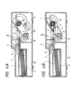
- Figs. 4A and 4B are cross-sectional views showing a recording apparatus B which performs recording by installing in it an ink cassette Awhich will be described later.
- the recording apparatus B records images on a recording sheet 1 serving as a recording medium in accordance with the image signals which are transmitted from another apparatus.
- the recording sheets 1 serving as a recording medium are stacked for storage in a sheet cassette 11, and are fed one by one from the top by driving a feed roller 7 rotatively in the direction indicated by an arrow a.
- the recording sheet 1 thus fed is pinched under pressure by a driving roller 5 which is driven to rotate in the direction indicated by an arrow b and a pressure roller 6 so that the sheet is further conveyed to a position where the recording is started in a first color.
- Fig. 4B the arrangement is made so that the above-mentioned recording sheet 1 and an ink sheet 2 are pressed by a recording head 3 serving as recording means onto a platen roller 4 side to allow them to be superposed; the recording sheet 1 and the ink sheet 2 are conveyed by driving the driving roller 5 serving as feeding means rotatively in the direction indicated by an arrowc; thus, in synchronism with the conveyance of the recording sheet 1 and the ink sheet 2, the recording head 3 is caused to generate heat in accordance with the image signals to fuse (including sublimation, hereinafter the same) the ink which is coated on the ink sheet 2; and the fused ink is transferred to the recording sheet 1 to form images thereon.
- fuse including sublimation, hereinafter the same
- the recording is completed for one image portion in one color. It is then arranged that when three image portions in three colors are completed likewise, the recording sheet 1 is conveyed by a pair of delivering rollers 8 and 9 to let it out from the apparatus.
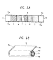
- the ink sheet 2 in the present embodiment is an elongated transfer sheet as shown in Fig. 2A on which coloring matters, Y (yellow), M (magenta), and C (cyanogen), are coated in each of the separated sections in that order.
- a lead 70 which is a first guiding member and a lead 71, a second guiding member, are mounted, respectively.
- the ink sheet is installed in an ink sheet cassette A constituted as described later.
- the leads 70 and 71 are respectively wound around the outermost circumference and the innermost circumference of the ink sheet 2 in order to implement the protection of the ink sheet, the improvement of its handling, and its holding as shown in Fig. 2B.
- the lead 71 wound around the innermost circumference and the lead 70 wound around the outermost circumference are both configured in the same shape to suppress any increase in its manufacturing cost, but it may be possible to arrange the lead 71 wound around the innermost circumference to be configured without any lead holes 71a.
- Fig. 1A is a cross-sectional view showing an ink sheet cassette A in which an elongated ink sheet 2 wound around a lead 71 (hereinafter referred to as a supply reel 30) is installed.
- Fig. 1 B is a perspective view showing the one end of the supply reel shown in Fig. 1Awhich engages with a supply reel driving device to be described later.
- Fig. 1C is a perspective view showing the both ends of the winding reel shown in Fig. 1Awhich engage with a winding reel driving device to be described later for winding up the lead and ink sheet.
- Fig. 1 D is a perspective view showing a sprocket which engages with the lead driving device to be described later for feeding the lead to the winding unit of the winding reel.
- elongated ink sheet 2 is wound around the lead 71 while a lead 70 is bonded to its free end.
- This lead 70 is wound around the winding reel 31 (on both sides) by the winding reel driving device which will be described later, thus winding up the ink sheet 2 subsequent to recording.
- the above-mentioned supply 30 is installed in a case 40.
- the winding reel 31 is rotatively supported by shafts 42 provided in the case 40.
- the one end of the supply reel 30 in the longitudinal direction fits into a pivot 32 mounted on a side wall 40b while the other end (on the right-hand side in Fig. 1A) fits into a holder 33 shown in Fig. 1 B.
- the supply reel is installed in the case 40.
- coupling nails 33b are formed on the inner circumference of the foregoing holder 33.
- the coupling nails 33b are arranged to engage with the supply reel driving device which will be described later.
- a gear 31a is formed as shown in Fig. 1 C.
- the pinion gear 34 which engages with the gear 31 a is fixed to a shaft having a coupling nail 34a which is formed at one end (on the right-hand side in Fig. 1 C) of the shaft.
- This coupling nail 34a is arranged to engage with the winding reel driving device which will be described later so that the pinion gear 34 is driven.
- a plurality of winding nails 31c are arranged for the cylindrical part 31 b of the winding reel 31 to wind up the lead 70.
- each of the winding nails 31c is arranged at the same phase to the winding reels 31 on both sides.
- the sprockets 35 are the guide member conveying means which feeds the above-mentioned lead 70, and fixed to the shaft at one end of which the coupling nail 35a is formed as shown in Fig. 1 D.
- This coupling nail 35a engages with the lead driving device which will be described later to drive the sprockets 35.
- the feeding teeth 35b are provided to convey the lead 70 to the winding nails 31 c on the cylindrical parts 31 b which are the winding parts of the winding reels 31.
- each of the feeding teeth 35b is provided at the same phase to the sprockets 35 on both sides.
- the case 40 which installs the foregoing supply reel 30 therein has a recording window40a in its central part where the ink sheet 2 is exposed as shown in Fig. 1A.
- an extrusion 40c is formed on the side wall 40b on one side (lefthand side in Fig. 1A).
- the leading end of the pivot 32 fits in a recess 40i provided for the extrusion 40c, and at the same time, it is coupled to the spring 41 mounted on the circumference of the extrusion 40c.
- This pivot 32 is supported by the spring 41 rockingly, and allowed to fit in the inner diameter of the end portion 71 b of the lead 71 of the supply reel 30.
- the holder 33 which fits in the supply reel 30 is rotatively supported in the holder 40e.
- the shafts 42 are provided to support the winding reels 31 rotatively.
- fixing members 42a are fixed to prevent the winding reels 31 from falling off in the longitudinal direction of the shafts.
- the holes 40h are formed, respectively, to receive the shafts of the pinion gear 34 and that of the sprocket 35. Then, on the inner plane of the foregoing side wall 40b, the foregoing spring 41 is mounted. By this spring 41, the supply reel 30 is biased in the direction indicated by an arrow d in Fig. 1A.
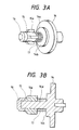
- the supply reel driving device which drives the holder 33 fitting in the foregoing supply reel 30 is provided as shown in Figs. 3Aand 3B with a reel driving shaft 14 having in its center a polygonal shaft 14a and an abutting portion 14b on which the leading end 33a of the holder 33 abuts; a sliding member 15 the inner contour of which is polygonal corresponding to the shaft 14a so that it fits and slides freely along the outer circumference of the shaft 14a in the longitudinal direction, and which also has the nails 15a engaging with the coupling nails 33b of the holder 33 in the radial direction to stop them; a spring 17 which gives a one-way bias to the sliding member 15; and a fixing member 16 mounted on the shaft 14a which engages with the leading end of the sliding member 15 to hold it.
- the above-mentioned driving shaft 14 is structured so that a constant load is given thereto when rotating, and that a constant tension is provided for the ink sheet 2 which is drawn from the supply reel 30.
- the sliding member 15 fitting in the foregoing reel driving shaft 14 is arranged in order to make it easier to engage with the holder 33, and when the sliding member 15 and the coupling nails 33b engage with each other, the sliding member 15 slides while rotating slightly for releasing the contact between the nails 15a and the coupling nails 33b even if these nails abut upon each other, and complete the intended engagement because there is a space between the inner diameter of the sliding member 15 and the outer diameterof the shaft portion 14a of the reel driving shaft 14.
- the winding reel driving device which engages with the coupling nails 34a on one end side of the foregoing pinion gear 34 and drives the winding reel 31 is provided as shown in Figs. 5A and 5B with the winding reel driving shaft 60 having a rectangular nail 60a in its center; a spring 61 which gives a one-way bias to the winding reel driving shaft 60; a bearing 62 having a bearing portion 62a which allows the winding reel driving shaft 60 to fit in it slidably in the longitudinal direction, and supports it rotatively in the circumferential direction; and a fixing member 63 mounted on the shaft portion of the winding reel driving shaft 60.
- the arrangement is made so that a rotational force is given to the foregoing winding reel driving shaft 60 through a driving force transmission system which is not shown, and that the ink sheet 2 is wound up around the winding reel 31 when recording.
- a constant load is exerted on the winding reel driving shaft 60 when rotating, and that a constant tension is given to the ink sheet 2 which is drawn from the supply reel 30.
- the foregoing spring 61 giving the one-way bias to the winding reel driving shaft 60 is arranged in order to make it easier to engage with the coupling nails 34a provided on one end of the pinion gear 34, and when the rectangular nail 60a and coupling nails 34a engage with each other, the winding reel driving shaft 60 slides in the longitudinal direction while rotating slightly for releasing the contact between the rectangular nail 60a and the coupling nails 34a even if these nails abut upon each other, and complete the intended engagement because there is a space between the end face 60b of the nail 60a and the end face 62b of the bearing 62.
- the lead driving device fitting in the coupling nails 35a provided on the one end of the foregoing sprocket 35 for feeding the lead 70 is provided as shown in Figs. 6A and 6B with the sprocket driving shaft 64 having a rectangular nail 64a in its center; a spring 65 which gives a one-way bias to the sprocket driving shaft 64; a bearing 66 having a bearing portion 66a which allows the sprocket driving shaft 64 to fit in it slidably in the longitudinal direction, and supports it rotatively in the circumferential direction; and a fixing member 67 mounted on the shaft portion of the sprocket driving shaft 64.
- the arrangement is made so that a rotational force is given to the foregoing sprocket driving shaft 64 through a driving force transmission system which is not shown, and that the lead 70 stored in the supply reel 30 is fed to the wounding nails 31c provided for the cylindrical portion 31 b ofthewinding reel 31.
- the foregoing spring 65 giving the one-way bias to the sprocket driving shaft 64 is arranged in order to make it easier to engage with the coupling nails 35a provided on one end of the sprocket 35, and when the rectangular nail 64a and coupling nails 35a engage with each other, the sprocket driving shaft 64 slides in the longitudinal direction while rotating slightly for releasing the contact between the rectangular nail 64a and the coupling nails 35a even if these nails abut upon each other, and complete the intended engagement because there is a space between the end face 64b of the nail 64a and the end face 66b of the bearing 66.
- this lead driving device is of the structure which is almost the same as the foregoing winding reel driving device, but the revolution to be transmitted is the difference between them. It has a relationship of the lead driving device ⁇ the winding reel driving device.
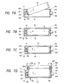
- Figs. 7A, 7B, 7C, and 7D are cross-sectional views illustrating the procedure with which to install the foregoing supply reel in the ink sheet cassette A.
- the mode of the supply reel before the installation in the ink sheet cassette A is that the lead 70 is wound around the outermost circumference of the ink sheet 2 as shown in Fig. 2B, so that the protection of the ink sheet and the improvement of its handling are implement.
- the lead 71 is wound around the innermost circumference of the ink sheet 2 to maintain the holding of the ink sheet.
- a pivot 32 is fixed to an extrusion 40c on the wall side 40b of a case 40 through a spring 41.
- a holder 33 is rotatively supported in a hole 40e.
- an operator inserts the supply reel 30 into the tapered part 32a of the pivot 32 in the direction indicated by an arrow h.
- This tapered part 32a fits in the end face of the inner diameter 71 b of the lead 71 of the supply reel 30.
- the pivot 32 is supported by the spring 41 rockingly, the reel 30 can be inserted easily while inclining it.
- the pivot 32 is supported by the spring 41 so that the supply reel 30 can slide slightly in the longitudinal direction. While keeping the depression in the direction indicated by an arrow h, the operator installs the supply reel 30 in the direction indicated by an arrow g as shown in Fig. 7B.
- the supply reel 30 When the depression exerted in the direction indicated by an arrow h is released, the supply reel 30 is biased in the direction indicated by an arrow d by the force of the spring 41 as shown in Figs. 7C and 7D.
- the end face 71 b of the inner diameter of the lead 71 of the supply reel 30 is inserted into the tapered part 33c of the holder 33.
- the holes 70a of the lead are positioned just above the feeding teeth 35b of the sprocket 35.
- Figs. 9A, 9B, and 9C are cross-sectional views showing the state where the foregoing ink sheet cassette A is installed in the recording apparatus B.
- the cassette installation part of the recording apparatus B is arranged so that the foregoing reel driving shaft 14 is rotatively mounted on a shaft 18 which is fixed on a rear chassis 19.
- the above-mentioned rear chassis 19 is fixed to a main chassis 20.
- a front chassis 21 is fixed.
- pins 22 and 23 are respectively fixed in two places left and right the hole 21a where the ink sheet cassette A is inserted.
- the pins 22 and 23 fit in the holes 40f and 40g formed on the case 40 of the ink sheet cassette A.
- the hole 40g on one side is elongated. Therefore, the positioning of the ink sheet cassette A to the recording apparatus B is executed by means of the coupling nails 33b of the holder33 of the supply reel 30, the sliding member 15 of the reel driving device, and holes 40f and 40g of the case 40 and the pins 22 and 23.
- a pressure board 24 capable of being opened and closed is arranged, and on this pressure board 24, spring members 25 are mounted.
- the biasing strength of these spring members 25 is defined stronger than the biasing strength of the spring 41 provided forthe ink sheet cassette A. It is then arranged that when the pressure board 24 is closed, the spring members 25 press the side board 40b in the vicinity of the place where the spring 41 is provided for the ink sheet cassette A.
- the abutting part 14b is caused to abut upon the end face 33a of the holder 33 by the biasing force of the spring members 25, and at the same time, the supply reel 30 is biased in the direction indicated by an arrow e in Fig. 9A.
- the supply reel 30 slides in the direction indicated by the arrow e so that the end face 33b which has abutted on the inner surface of the side wall 40d of the case 40 is caused to be released, hence allowing the supply reel 30 to be rotative.
- the arrangement is made so that the extrusion 32b of the pivot 32 is caused to abut on the bottom of the recess 40i inside the extrusion 40c, and the positions in the longitudinal and circumferential directions of the reel are determined.
- the nail 34a at the end on the one side of the pinion gear 34 which drives the winding reel 31 the nails 35a at the end on the one side of the sprocket 35 which feeds the lead 70, the nails 60a of the winding reel driving shaft 60, and the nails 64a of the sprocket driving shaft 64 are coupled, thus enabling the driving forces from the winding reel driving device and the lead driving device to be transmitted.
- Figs. 8A, 8B, 8C, and 8D are cross-sectional views illustrating the operation to wind up the lead of the foregoing supply reel around the winding reel of the ink sheet cassette A.
- the supply reel installed in the ink sheet cassette A has the holes 70a of the lead 70 positioned just above the feeding teeth 35b of the sprocket 35 as shown in Fig. 8A.
- the lead 70 is conveyed in the direction indicated by an arrow j.
- the lead driving device suspends the rotation when the holes 70a of the lead 70 reach the position just above the winding nails 31c arranged on the cylindrical part 31 b of the winding reel 31 as shown in Fig. 8B.
- the force from the winding reel driving device is transmitted to the winding reel 31 to rotate it in the direction indicated by an arrow k.
- the holes 70a of the lead 70 which have been conveyed by the lead driving device are allowed to engage with the winding nails 31c arranged on the cylindrical part 31 b of the winding reel 31.
- the lead 70 is wound around the cylindrical part 31 b of the winding reel 31. Further, the winding reel 31 is rotated in the direction indicated by an arrow k in Fig. 8D to wind all the lead 70 around the cylindrical part 31 b of the winding reel 31.
- the lead 70 is integrated with the winding reel 31, making it possible to wind up the ink sheet to be used along the recording operation of the recording apparatus B.
- Figs. 10A and 10B are views schematically illustrating the structure of the recording apparatus B in which the inksheetcassetteAis installed.
- a thermal head 3 is mounted on a supporting arm 50 which is rotative together with a shaft 57 around the shaft 57 rotatively mounted on a chassis (not shown).
- a platen roller 4, a driving roller 5, and pressure roller 6 are integrally mounted, respectively, on the shafts 54, 55, and 56 rotatively mounted on the chassis (not shown).
- a reference numeral 58 designates a stopper which is mounted on the chassis (not shown). The stopper 58 is arranged to abut on the supporting arm 50.
- a reference numeral 59 designates a sensor which detects the leading end of a recording sheet 1.
- the thermal head 3 is pressed to the platen roller4 by the rotational movement of the supporting arm 50 with the recording sheet 1 and an ink sheet 2 pinched between them.
- the recording sheet 1 is conveyed by means of the driving roller 5 and the pressure roller to the position where its leading end is detected by the sensor 59.
- a first color portion (yellow, for example) of the ink sheet 2 is set at the starting position of recording, the first color portion is ready for recording.
- the driving roller 5 is rotated in the direction indicated by an arrow X1 while the recording sheet 1 is being pinched by the driving roller 5 and pressure roller 6.
- the shaft 57 is rotated in the direction indicated by an arrow x 2 by a supporting arm driving unit which is not shown. Since the supporting arm 50 is integrally formed with the shaft 57, the arm is rotated in the direction indicated an arrow x 3 .
- the thermal head 3 mounted on the supporting arm 50 presses the platen roller 4 so that the recording sheet 1 and the ink sheet 2 are pinched.
- the coloring matter (yellow) on the ink sheet 2 is transferred to the recording sheet 1 by the heat generated by the thermal head 3.
- the thermal head 3 is allowed to press the platen roller 4 with a given constant force by means of this torque limiter.
- the driving roller 5 is rotated in the direction indicated by an arrow x 4 .
- the shaft 57 is rotated by the supporting arm driving unit which is not shown in the direction indicated by an arrow x 5 .
- the supporting arm 50 is rotated in the direction indicated by an arrow X6 to cause the thermal head 3 to retract from the platen roller 4.
- the supporting arm driving unit which is not shown releases the transmission force to the shaft 57 so that the supporting arm 50 is held in the position where it abuts on the stopper.
- the driving roller 5 is continuously rotated in the direction indicated by the arrow x 4 to convey the recording sheet 1 in corporation with h the pressure roller 6, and stop it in the position where the leading end of the recording sheet 1 is detected by the sensor 59. Also, during this period, the ink sheet 2 is wound up by the winding reel 31, which will stop when a second coloring matter on the ink sheet 2 arrives at the position where the recording begins.
- the driving roller 5 is rotated in the direction indicated by the arrow X1 to cause the thermal head 3 to press the platen 4 as in the state shown in Fig. 10A, thus the second color recording begins. Thereafter, a third color recording is made in the same manner, and then, one image recording will be completed.
- the ink sheet 2 is wound up by the winding reel 31. After the recording on a given number of recording sheets is completed, the ink sheet 2 is further wound up. Then, the lead 71 provided for the very last end of the ink sheet 2 is wound around the winding reel 31.
- the operator removes the lead 70 integrated with the winding reel 31 from the inkcassette A in a state that the lead 71 has been completely wound around the winding reel 31. When removing, the holes 70a of the lead 70 are drawn out from the winding nails 31 c provided for the cylindrical part 31 b of the winding reel 31, and then, the lead 70 is removed from the cylindrical part 31 b of the winding reel 31.
- the holes 70a of the lead 70 are formed at equal intervals and are allowed to engage with the sprocket 35 for conveying the ink sheet 2, and further, the ink sheet is wound up by enabling the holes to engage with the winding nails 31 of the winding reel 31.
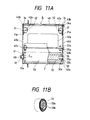
- the ink sheet 2 is a transfer sheet on which coloring matters, Y (yellow), M (magenta), and C (cyanogen), are coated in the respective sections in that order, and one end thereof is connected to the supply reel which will be described later, while the other end (free end) has a lead 70 bonded thereto as the guiding member.
- the mode of the above-mentioned ink sheet 2 before its installation in the ink sheet cassette A is that the lead 70 is wound around the outermost circumference of the ink sheet 2 as shown in Fig. 12B in order to implement the protection of the ink sheet and the provision of its easier handling. It is then arranged that this ink sheet cassette A can be detachably installed in the apparatus main body 10.
- Fig. 11A is a cross-sectional view illustrating the ink sheet cassette A in which the supply reel having an ink sheet wound around it as a strap member is installed.
- Fig. 11 B is a perspective view showing one end of the supply reel shown in Fig. 11Awhich engages with the supply reel driving device to be described later.
- the elongated ink sheet 2 is wound around the supply reel 30 which is a molded product.
- a lead 70 is bonded to the free end of the sheet.
- the lead 70 is wound around the winding reels 31 (on both sides) by the winding reel driving device which will be described later, and serves as a winding member.
- the above-mentioned supply reel 30 is installed in a case 40 in a state that the reel has wound up the ink sheet 2.
- the above-mentioned winding reel 31 is rotatively supported by the shaft 42 which is arranged in the case 40.
- a pivot 32 is formed, while at the other end, a small diameter hollow cylindrical part 33 is formed as shown in Fig. 11 B. Then, on the inner circumference of the hollow cylindrical part 33, a coupling nail 33b is formed. This coupling nail 33b is arranged to engage with the supply reel driving device which will be described later.
- the case 40 which receives the foregoing supply reel 30 has a recording window 40a in the central part thereof as shown in Fig. 11A to allow the ink sheet 2 to be exposed.
- a recess 40i is formed to rotatively support the pivot 32 of the supply reel 30. This recess 40i is so formed that it has a depth allowing the supply reel 30 to be slightly slidable in the longitudinal direction.
- a hole 40e is formed, which is capable of receiving the small diameter hollow cylindrical part 33 of the supply reel 30.
- the inner diameter of this hole 40e is formed larger than the outer diameter of the small diameter hollow cylindrical part 33.
- a flat spring 41 is mounted on the inner plane of the foregoing side wall 40b.
- the supply reel 30 is biased in the direction indicated by an arrow d in Fig. 11A.
- the end face 30a of the supply reel 30 is caused to abut on the inner face of the side wall 40d on the other side of the case 40.
- the rotation of the supply reel 30 is regulated. Therefore, when the cassette A is removed from the recording apparatus B, the supply reel does not rotate idle.
- the ink sheet 2 does not slack, either, accordingly.
- the supply reel 30 slides by the biasing force of the flat spring 41 in the direction indicated by the arrow d in Fig. 11A, but it is arranged that the pivot 32 does not fall off from the recess 40i at that time.
- an operator inserts the pivot 32 of the supply reel 30 into the foregoing recess 40i in the direction indicated by an arrow h.
- This recess 40i is formed in a depth good enough to allow the supply reel 30 to slide in the longitudinal direction.
- the operator installs the supply reel 30 in the direction indicated by an arrow h as shown in Fig. 7B.
- the supply reel 30 is biased in the direction indicated by the arrow d by the flat spring 41 mounted on the inner face of the foregoing side wall 40b as shown in Figs. 7C and 7D.
- the outer diameter of the small diameter hollow cylindrical part 33 is inserted into the inner diameter of the foregoing hole 40e.
- the holes' 70a of the lead are positioned just above the feeding teeth 35b of the sprocket 35.
- the operator After recording the inksheet2 is wound up by the winding reel 31, and when the recording for a given number of recording sheets is completed, the operator removes from the cassette A the supply reel 30 and the lead 70 integrated with the winding reel 31 which has the used ink sheet wound around it. When removing, the holes 70a of the lead 70 are drawn out from the winding nails 31c provided forthe cylindrical part 31 b of the winding reel 31. Then, the lead 70 is removed from the cylindrical part 31 b of the winding reel 31, and a new supply reel 30 is installed.
- the lead 70, or the first guiding member, and the lead 71, or the second guiding member, bonded to both ends of the ink sheet, respectively, serve as substitutes for the winding reel and supply reel.
- the ink sheet before use is in a state that it is wound around the second guiding memberwhich is a substitution for the supply reel.
- the ink sheet after use is wound around the first guiding member which is a substitution for the winding reel. Therefore, any supply reel and winding reel are not needed.
- the parts can be reduced, and the intended adoption of inexpensive materials can be implemented at the same time.
- the supply reel having an ink sheet wound around it is installed in the cassette, and the guiding member bonded to the free end of the ink sheet serves as the winding member of the winding reel which winds up the ink sheet. Therefore, the used ink sheet is discarded together with the guiding member serving as the winding member, and then, the cassette and the empty-cored supply reel become reusable. Accordingly, the unit price of the cassette can be lowered, leading to the implementation of lowering the total cost of the recording apparatus which uses such a cassette.
- the cassette and the empty-cored supply reel can be reused, it is possible to obtain a recording apparatus for which the environmental protection is considered with respect to the life cycle (manufacturing ⁇ using ⁇ collecting ⁇ recycling) of the apparatus.
- the first embodiment and the second embodiment set forth above are of such a structure that no winding reel is needed, while the used inksheet is discarded. Now, the same structure of some other types will be further described according to a third embodiment and a fourth embodiment set forth below.
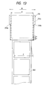
- Fig. 13 is a view illustrating an ink sheet as a strap medium, and an ink sheet leader as a guiding member.
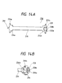
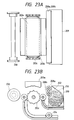
- Figs. 14Aand 14B are a cross-sectional view and a partially perspective view illustrating an ink reel for winding the ink sheet which serves as a guiding member.
- Figs. 15A to 15C are views illustrating a state where the ink sheet and ink leader member are wound around the ink reel.
- Figs. 16A and 16B are cross-sectional views illustrating the recording system of a recording apparatus which records with the foregoing ink reel installed therein. Figs.
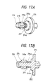
- FIG. 17Aand 17B are a perspective view and a cross-sectional view showing a reel base which fits in the ink reel according to the present embodiment.
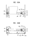
- Figs. 18A and 18B are cross-sectional views showing the main body installing therein the ink reel having the guiding member of the present embodiment wound around it is installed.
- Figs. 19A to 23B are cross-sectional views showing each state that the ink sheet utilizing the guiding member of the present embodiment is being fed automatically.
- the recording apparatus is the one which records images on a recording sheet 201 which serves as a recording medium in accordance with image signals transmitted from the other apparatus.
- the recording sheet 201 which is inserted from a manual inlet 206 is fed by a feeding roller 204 so that it is wound around a platen 203b.
- a recording head 203a constituting recording means 203 presses the superposed recording sheet 201 and the ink sheet 202 which serves as the recording medium to the rotative platen roller203b side.
- the recording sheet 201 and the ink sheet 202 are conveyed, and then, in synchronism with the conveyance of the foregoing recording sheet 201 and ink sheet 202, the recording head 203a generates heat in accordance with the image signals to fuse (including sublimation, hereinafter the same) the coated ink on the ink sheet 202. It is thus arranged that the fused ink is transferred to the recording sheet 201 to form images.
- the recording sheet 201 on which the given images are formed by the above-mentioned recording means 203 is further conveyed. It is then arranged that the recorded sheet is being fed by the delivering rollers 205 to let it out from the apparatus through the outlet 207.
- the ink leader member 210 uses a film of 10 f..lm to 300 ⁇ m thick, which is wider than the width of the ink sheet 202 which is a strap medium.
- the stoppers 210a and 210b having the width which still wider.
- One side of the elongated ink sheet 202 is wound around the ink reel 230 which will be described later. The other side thereof is bonded to the ink leader member 210 by an adhesive tape, an adhesive bonding, or the like.
- the foregoing ink leader member 210 has the holes 210c which are provided for the automatic loading, and engage with the sprocket 203c which will be described later to convey the ink sheet 202.
- the positions of the holes 210c are in the direction substantially in parallel to the longitudinal direction of the ink sheet 202.
- the holes are provided continuously on both sides of the ink leader member 210 at a given pitch p.
- the width A between the opposing holes 210c is wider than the width C in the shorter direction of the ink sheet 202, and is narrower than the width B between the foregoing opposing stoppers 210a and 21 Ob. This arrangement is required to avoid any interference of the recording head 203a and sprocket 203c which utilize the ink leader member 210 as a bias to the platen at the time of the automatic installation of the ink sheet 202, which will be described later.
- a pivot 232 is formed on one end side in the longitudinal direction of the ink reel 230 which serves as the strap medium winding member, while on the other end side, a coupling part 233 is formed to engage with the reel 213 which will be described later.
- the foregoing coupling part 233 is configured almost like a hollow cylinder having the leading end 233a and coupling nails 233b.
- an ink sheet winding part 231 which is the first winding part is arranged.
- the ink sheet leader winding parts 234a and 234b which are the second winding parts are formed, respectively.
- the outer diameters of the foregoing ink sheet leader winding parts 234a and 234b are larger than the outer diameter of the foregoing ink sheet winding part 231 when the ink sheet 202 is wound around it in a given quantity, thus avoiding any interference between the above-mentioned wound up ink sheet 202 and the ink leader members 210.
- the flange type ink leader stoppers 235a and 235b are formed. On the circumferences thereof, many numbers of the slits 236 are arranged to engagedly stop the stoppers 210a and 210b of the ink leader member 210.
- the ink sheet 202 is wound around the foregoing ink sheet winding part 231 of the ink reel 230.
- the ink leader member 21 is wound around the foregoing ink leader winding parts 234a and 234b.
- the ink leader member 210 tends to become loose at all times due to its own resiliency, but the rear ends of the ink leader stoppers 210a and 21 Ob are pinched by the extrusion 236a and slit wall 236b provided for the slit 236 of the ink leader stoppers 235a and 235b of the ink reel 230 so that it does not become loose by its own force.
- the ink leader member 210 is long enough in the direction in which it is wound up and is wound around the foregoing ink leader winding parts 234a and 234b twice or three times, the ink leader member can be held on the slit only by its own resiliency. There is then no problem even if the extrusion 236a is not provided.
- the reel 213 which fits in the foregoing ink reel 230 comprises a reel base 214 having a polygonal shaft 214a in its center and an abutting part on which the leading end of the coupling part 233 of the forgoing ink reel 230; a sliding member 215 having the nails 215a the inner configuration of which is polygonal corresponding to the shaft 214a and is slidable on the outer circumference of the shaft 214a in the longitudinal direction to engage with the coupling nails 233b of the coupling part 233; a spring 217 which gives a one-way bias to the sliding member 215; and a fixing member 216 mounted on the shaft 214a to engagedly hold the leading end of the sliding member 215 as shown in Figs. 17A and 17B.
- a torque limiter (not shown) is connected to give it a constant load when rotating. It is thus arranged that a constant tension is given to the ink sheet 202 being drawn from the ink reel 230.
- the sliding member 215 of the foregoing reel 213 is provided to make it easier to engage with the ink reel 230.
- the sliding member 215 and the coupling nails 233b engage with each other the sliding member 215 slides while rotating slightly in the rotating direction to disengage the contact between the nails 215a and coupling nails 233b for coupling even if these nails abut upon each other because there is a space between the inner diameter of the sliding member 215 and the outer diameter of the shaft 214a of the reel 213.
- the mounting part of the recording apparatus for the ink reel 230 is arranged as shown in Figs. 18Aand 18B to allow the foregoing reel 213 to be rotatively mounted on the shaft 218 fixed to the rear chassis 219.
- the above-mentioned chassis 219 is mounted on the main chassis 220.
- a front chassis 221 is mounted on the main chassis 220.
- forthefront chassis 221 a pressure board 224 capable of being opened and closed is provided.
- this pressure board 224 there is a recess 240c which fits on the foregoing pivot 232, and between the pressure board 224 and this recess 240c, a spring member 225 is mounted.
- the abutting part 214b is caused by the bias of the spring member 225 to abut upon the leading end 233a of the coupling part 233.
- the pivot 232 abut on the bottom of the recess 240c at that time. In this way, the reel is positioned in the longitudinal direction.
- the ink leader member 210 is detected by a lead sensor (not shown) arranged above the sprocket 203c formed on the platen roller 203b.
- the recording head 203a is lowered by means of a driving device which is not shown, and then, stopped at a given interval to the platen roller 203b. This movement results from the event that the abutting part 203a' of the recording head 203a abuts upon the ink leader part 210 to bias the ink leader member 210 to the sprocket 203c side.
- the platen roller 203b is driven to cause the sprocket 203c to rotate in the direction indicated by an arrow d.
- the holes 210c provided for the ink leader member 210 engage with the teeth of the sprocket 203c to convey the ink leader member 210 in the direction indicated by an arrow e.
- the ink leader member 210 thus conveyed is nipped by a pair of feeding rollers 208a and 208b.
- These feeding rollers 208a and 208b are coupled with the platen roller 203b by the gear train which is not shown.
- the circumferential speed of the foregoing feeding rollers 208a and 208b is equal to or slightly faster than that of the platen roller 203b.
- the rotation of the feeding rollers 208a and 208b is suspended when an ink sheet head mark of the ink sheet 202 being drawn by the feeding rollers 208a and 208b from the ink reel 230 is detected by a sensor (not shown) which is mounted in the vicinity of the recording head 203a.
- the recording head 203a is returned to its initial position by a driving device which is not shown.
- the ink sheet is being fed during the printing by the force exerted by the rotation of the platen roller 203b when the recording head 203a is depressed to the recording sheet 201.
- the recorded ink sheet 202 is conveyed by the feeding rollers 208a and 208b to a ink sheet retainer 209, or a collecting member, arranged in the downstream of the feeding rollers 208a and 208b.
- This ink sheet retainer 209 is equipped as an individual packaging case for the ink reel 230, and the operator in'stalls it in the apparatus main body for use together with the above-mentioned ink reel 230 for collecting the used ink sheet 202 which is being fed from the ink reel 230.
- the ink sheet 202 which has been used to the very last is separated from the ink reel 230. All the used ink sheets are ultimately stored in the inksheet retainer 209. Therefore, the operator simply removes the used ink sheets 202 together with the ink sheet retainer 209 and discard them as non-flammable matter. It is extremely easy to handle them. Also, the empty ink reel 230 which is a mold product can be collected for reuse in an appropriate route, making it possible to implement the resource saving.
- Fig. 24 is a view illustrating an ink sheet serving as a strap medium, and an ink sheet leader part as a first guiding member.
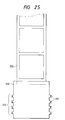
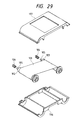
- Fig. 25 is a view illustrating an ink sheet serving as a strap medium and a reel sheet as a second guiding member.
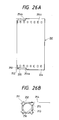
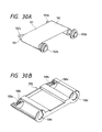
- Figs. 26A and 26B are views illustrating the state where the ink sheet and ink leader member are wound around the reel sheet which has been wound up cylindrically.
- an ink leader member 254 is bonded by an adhesive tape or the like (not shown) to the one end of an elongated ink sheet 253.
- an adhesive tape or the like (not shown)
- a polyethylene terephthalate, polyvinyl chloride, orthe like having a thickness of 10 ⁇ m to 300 ⁇ m without containing any plasticizer is used. Its width is wider than that of the ink sheet.
- the stoppers 254a and 254b which are wider still are provided.
- the holes 254c are arranged for the automatic installation, which engage with the above-mentioned sprocket 203c to feed the ink sheet 253.
- the positions of the holes 254c are substantially in parallel with the longitudinal direction of the ink sheet 253, and the holes are continuously provided on both sides of the ink leader member 254 at a given pitch p.
- the opposing width A of the holes 254c is wider than the width C of the ink sheet 253 in the shorter direction, but is narrower than the opposing width B of the foregoing stoppers 254a and 254b. This is arranged in order to avoid any interference of the recording head 203a and sprocket 203c which utilize the ink leader member 254 for biasing the platen when the ink sheet 253 is automatically installed as described above.
- Fig. 25 the lead sheet 250 which serves as a second guiding member is bonded by an adhesive tape or the like is bonded to the other end of the foregoing ink sheet 253.
- a polyethylene terephthalate, polyvinyl chloride, or the like having a thickness of 10 f..lm to 300 f..lm without containing any plasticizer is used. Its width is wider than that of the ink sheet 253, and the teeth 252 having slits 251 on a part thereof are formed.
- Fig. 25 represents a state that the teeth 252 are developed with respect to the reel sheet 250.
- the ink reel 261 winds up the reel sheet 250 around it to form a cylindrical reel sheet 250.
- the teeth 252 having the slits 251 is folded to rise.
- the ink sheet 253 is wound around the reel sheet 250, and the ink leader member 254 is also wound around the ink sheet 253 which has been wound up.
- the trailing ends of the ink leader stopper 254a and 254b are pinched and held by the slit 251 of the foregoing teeth 252.
- the reel 260 fitted into the foregoing cylindrical reel sheet 250 comprises a sliding member 265 having a polygonal shaft 264a which fits in the center of the reel base 264, the nails 265a the inner configuration of which is polygonal corresponding to the shaft 264a and slidable on the outer circumference of the shaft 264a in the longitudinal direction to engage with the teeth 252 in the circumferential direction, a sliding member 265 having a flange 265b which abuts upon the abutting part 255 of the foregoing reel sheet 250, a spring 267 which gives a one-way bias to the foregoing sliding member 265, and a fixing member 266 mounted on the foregoing shaft 264a to stop the end of the foregoing sliding member 265.
- a torque limiter (not shown) is connected to give a constant load thereto when rotating. It is thus arranged that a constant tension is given to the ink sheet 253 being drawn from the cylindrical reel sheet 250.
- the sliding member 265 of the foregoing reel 260 is provided to make it easierto engage with the teeth 252 of the cylindrical reel sheet 250. When the sliding member 265 and the teeth 252 engage with each other, the sliding member 265 slides while rotating slightly in the rotating direction to disengage the contact between the nails 265a and teeth 252 for coupling even if these nails and teeth abut upon each other because there is a space between the inner diameterof the sliding member 265 and the outer diameter of the shaft 264a of the reel base 264.
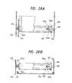
- the mounting part of the recording apparatus for the ink reel 261 is arranged as shown in Figs. 28Aand 28B to allow the foregoing reel 260 to be rotatively mounted on the shaft 268 fixed to the rear chassis 269.
- the above-mentioned chassis 269 is mounted on the main chassis 270.
- a front chassis 271 is mounted on the main chassis 270.
- a pressure board 274 capable of being opened and closed is provided for the front chassis 271.
- this pressure board 274 there is provided an extrusion 274c which fits in the inner circumference of the foregoing cylindrical reel sheet, and between the pressure board 274 and this extrusion, a spring member 275 is mounted.
- the flange 265b is caused by the bias of the spring member 275 to contact the abutting part 255 of the cylindrical reel sheet 250.
- the ink sheet 253 is automatically fed, and the ink sheet which has been used up to the very end becomes a strap because the cylindrical reel sheet 250 is ultimately unfastened. All of them are stored in the ink sheet retainer 209 after all.
- the operator can simply take out the used ink sheet 253 together with the ink sheet retainer 209 and discard them as nonflammable matter. Therefore, it is easier for the operator to handle the ink sheet. Also, no empty reels remain to make the further promotion of the resource saving possible.
- the strap medium is wound around the first winding part which is a strap medium winding up member, and the guiding member bonded to its free end is wound around the second winding member.
- the used strap medium, and the strap medium winding member which is a mold product can be discriminated easily without any trouble on the part of the operator. At the same time, since the mold product can be collected for reuse, it is possible to contributing to the resource saving.
Landscapes
- Impression-Transfer Materials And Handling Thereof (AREA)
Applications Claiming Priority (6)
| Application Number | Priority Date | Filing Date | Title |
|---|---|---|---|
| JP253648/92 | 1992-08-31 | ||
| JP253646/92 | 1992-08-31 | ||
| JP25364692A JPH0679892A (ja) | 1992-08-31 | 1992-08-31 | 記録装置 |
| JP25364792A JPH0679939A (ja) | 1992-08-31 | 1992-08-31 | 記録媒体及び記録装置 |
| JP253647/92 | 1992-08-31 | ||
| JP25364892A JPH0679940A (ja) | 1992-08-31 | 1992-08-31 | 帯状媒体巻回部材及び記録装置 |
Publications (2)
| Publication Number | Publication Date |
|---|---|
| EP0586351A2 true EP0586351A2 (de) | 1994-03-09 |
| EP0586351A3 EP0586351A3 (en) | 1994-06-29 |
Family
ID=27334253
Family Applications (1)
| Application Number | Title | Priority Date | Filing Date |
|---|---|---|---|
| EP19930830359 Ceased EP0586351A3 (en) | 1992-08-31 | 1993-08-27 | Ink ribbon winding member for a recording apparatus |
Country Status (2)
| Country | Link |
|---|---|
| US (1) | US5727883A (de) |
| EP (1) | EP0586351A3 (de) |
Cited By (1)
| Publication number | Priority date | Publication date | Assignee | Title |
|---|---|---|---|---|
| EP1293352A1 (de) * | 2001-09-12 | 2003-03-19 | Sharp Kabushiki Kaisha | Farbfilmhalter und Farbfilmspule |
Families Citing this family (9)
| Publication number | Priority date | Publication date | Assignee | Title |
|---|---|---|---|---|
| US6439502B1 (en) | 1995-02-28 | 2002-08-27 | Kimberly-Clark Worldwide, Inc. | Dispenser for coreless rolls of products |
| US5851076A (en) * | 1997-10-23 | 1998-12-22 | Eastman Kodak Company | Printer adapted to guide a dye donor therein and method therefor |
| US6082664A (en) | 1997-11-20 | 2000-07-04 | Kimberly-Clark Worldwide, Inc. | Coreless roll product and adapter |
| US6226023B1 (en) * | 1999-05-10 | 2001-05-01 | Eastman Kodak Company | Thermal printing media pack |
| US6276849B1 (en) * | 1999-07-08 | 2001-08-21 | Brady Worldwide, Inc. | Printer spool and spool drive cone having radially extending teeth |
| NZ536895A (en) * | 2004-03-15 | 2007-03-30 | Brother Ind Ltd | Ink ribbon cartridge |
| JP4415792B2 (ja) | 2004-08-24 | 2010-02-17 | ブラザー工業株式会社 | 画像記録装置 |
| JP2006350285A (ja) * | 2005-05-17 | 2006-12-28 | Kyocera Mita Corp | 駆動カップリング機構及びそれを用いた画像形成装置 |
| JPWO2019065631A1 (ja) | 2017-09-27 | 2020-11-05 | シチズン時計株式会社 | インクリボン支持機構及びプリンタ |
Citations (4)
| Publication number | Priority date | Publication date | Assignee | Title |
|---|---|---|---|---|
| EP0294792A1 (de) * | 1987-06-08 | 1988-12-14 | Star Seimitsu Kabushiki Kaisha | Thermotransferdrucker und Tintenbandkassette dafür |
| EP0403775A2 (de) * | 1989-05-08 | 1990-12-27 | Mitsubishi Denki Kabushiki Kaisha | Drucker |
| EP0410396A2 (de) * | 1989-07-24 | 1991-01-30 | Canon Kabushiki Kaisha | Aufzeichnungsgerät |
| EP0488291A1 (de) * | 1990-11-29 | 1992-06-03 | Canon Kabushiki Kaisha | Farbblattkassette und Aufzeichnungsvorrichtung zu deren Verwendung |
Family Cites Families (16)
| Publication number | Priority date | Publication date | Assignee | Title |
|---|---|---|---|---|
| US1088039A (en) * | 1912-07-31 | 1914-02-24 | Christian H Nelson | Reel. |
| US1098863A (en) * | 1912-11-16 | 1914-06-02 | Seth Wheeler | Holder for paper-rolls. |
| US3623586A (en) * | 1969-08-27 | 1971-11-30 | Ncr Co | Ribbon spool |
| US3809218A (en) * | 1972-01-24 | 1974-05-07 | Newell Ind | Pliable tape record and reel therefor |
| DE2523808A1 (de) * | 1975-05-27 | 1976-12-09 | Berolina Edv Syst | Farbtuch |
| US4265553A (en) * | 1977-09-14 | 1981-05-05 | Exxon Research & Engineering Co. | Ribbon threading assembly for an impact printer |
| US4285480A (en) * | 1979-07-31 | 1981-08-25 | Harris Corporation | Cassette loading system and self-threading cassette for use therewith |
| US4475830A (en) * | 1981-09-29 | 1984-10-09 | International Business Machines Corporation | Spliceless ribbon structure having leader and trailer and method of manufacture therefor |
| JPS59196283A (ja) * | 1983-04-22 | 1984-11-07 | Hitachi Ltd | 印刷装置のインクリボン |
| DE3418545A1 (de) * | 1984-05-18 | 1985-11-21 | Olympia Werke Ag, 2940 Wilhelmshaven | Farbbandkassette fuer schreib- oder aehnliche bueromaschinen |
| JPS6166675A (ja) * | 1984-09-10 | 1986-04-05 | Fuji Xerox Co Ltd | インクドナ−フイルム取付装置 |
| JP2580569B2 (ja) * | 1986-05-30 | 1997-02-12 | ミノルタ株式会社 | 熱転写記録装置 |
| JP2535477Y2 (ja) * | 1987-11-25 | 1997-05-14 | 株式会社リコー | 感熱記録装置 |
| JPH03120984A (ja) * | 1989-10-04 | 1991-05-23 | Matsushita Electric Ind Co Ltd | 高品位テレビジョン表示装置 |
| JP2550191B2 (ja) * | 1989-12-25 | 1996-11-06 | 株式会社日立製作所 | 熱転写フィルム用カセットおよびこれに用いるインクフィルム |
| JPH04369574A (ja) * | 1991-06-19 | 1992-12-22 | Sony Corp | リボンカートリッジ |
-
1993
- 1993-08-27 EP EP19930830359 patent/EP0586351A3/en not_active Ceased
-
1996
- 1996-03-27 US US08/622,155 patent/US5727883A/en not_active Expired - Fee Related
Patent Citations (4)
| Publication number | Priority date | Publication date | Assignee | Title |
|---|---|---|---|---|
| EP0294792A1 (de) * | 1987-06-08 | 1988-12-14 | Star Seimitsu Kabushiki Kaisha | Thermotransferdrucker und Tintenbandkassette dafür |
| EP0403775A2 (de) * | 1989-05-08 | 1990-12-27 | Mitsubishi Denki Kabushiki Kaisha | Drucker |
| EP0410396A2 (de) * | 1989-07-24 | 1991-01-30 | Canon Kabushiki Kaisha | Aufzeichnungsgerät |
| EP0488291A1 (de) * | 1990-11-29 | 1992-06-03 | Canon Kabushiki Kaisha | Farbblattkassette und Aufzeichnungsvorrichtung zu deren Verwendung |
Cited By (2)
| Publication number | Priority date | Publication date | Assignee | Title |
|---|---|---|---|---|
| EP1293352A1 (de) * | 2001-09-12 | 2003-03-19 | Sharp Kabushiki Kaisha | Farbfilmhalter und Farbfilmspule |
| US6634589B2 (en) | 2001-09-12 | 2003-10-21 | Sharp Kabushiki Kaisha | Ink film holding device and film reel |
Also Published As
| Publication number | Publication date |
|---|---|
| EP0586351A3 (en) | 1994-06-29 |
| US5727883A (en) | 1998-03-17 |
Similar Documents
| Publication | Publication Date | Title |
|---|---|---|
| EP1334835B1 (de) | Bildformungsgerät und in das Bildformungsgerät montierte Farbbandkassette | |
| EP0489717A2 (de) | Kassette für Streifendrucker | |
| US5622440A (en) | Ink film cassette having a torque applying device therein | |
| WO2005100034A1 (en) | Thermal transfer printer/labeller specifically designed for cassettes or ready-to-use packages | |
| US5727883A (en) | Winding member for winding an ink sheet, housing member for housing such a winding member, and recording apparatus for recording on a recording medium by use of such a housing member | |
| US5799577A (en) | Stencil and stencil perforating device | |
| JPH0363155A (ja) | インクカートリッジ及び前記インクカートリッジを用いる記録装置 | |
| JP3549370B2 (ja) | カートリッジおよびこのカートリッジを用いた記録装置 | |
| US4772143A (en) | Reloadable ribbon cartridge | |
| JPH0471882A (ja) | インクシートカートリッジ及び前記インクシートカートリッジを用いる記録装置 | |
| CN1935526A (zh) | 色带盒和色带盒体 | |
| JP3033283B2 (ja) | 熱転写記録装置及びそのインク紙装填方法 | |
| JPH0679940A (ja) | 帯状媒体巻回部材及び記録装置 | |
| JPH10129065A (ja) | インクフィルム用リール及びカセット並びに熱転写記録装置 | |
| JPH0679939A (ja) | 記録媒体及び記録装置 | |
| JP3378864B2 (ja) | インクシートセット | |
| JPH0471883A (ja) | インクシートカートリッジ | |
| JPH06227073A (ja) | 被印字媒体の繰り出し装置 | |
| JPH07172017A (ja) | インクシート巻回部材およびそれを用いる記録装置 | |
| JPH07149017A (ja) | 熱転写記録装置 | |
| JP2000001013A (ja) | 熱転写プリンタ | |
| JPH07149016A (ja) | 熱転写リボン案内部材 | |
| JPH1148550A (ja) | カートリッジおよびこのカートリッジを用いた記録装置 |
Legal Events
| Date | Code | Title | Description |
|---|---|---|---|
| PUAI | Public reference made under article 153(3) epc to a published international application that has entered the european phase |
Free format text: ORIGINAL CODE: 0009012 |
|
| AK | Designated contracting states |
Kind code of ref document: A2 Designated state(s): DE FR GB IT |
|
| PUAL | Search report despatched |
Free format text: ORIGINAL CODE: 0009013 |
|
| AK | Designated contracting states |
Kind code of ref document: A3 Designated state(s): DE FR GB IT |
|
| 17P | Request for examination filed |
Effective date: 19941129 |
|
| 17Q | First examination report despatched |
Effective date: 19951020 |
|
| GRAG | Despatch of communication of intention to grant |
Free format text: ORIGINAL CODE: EPIDOS AGRA |
|
| STAA | Information on the status of an ep patent application or granted ep patent |
Free format text: STATUS: THE APPLICATION HAS BEEN REFUSED |
|
| 18R | Application refused |
Effective date: 19970626 |