EP0579932B1 - Dispositif de commande de papillon de moteur à combustion interne - Google Patents
Dispositif de commande de papillon de moteur à combustion interne Download PDFInfo
- Publication number
- EP0579932B1 EP0579932B1 EP93108635A EP93108635A EP0579932B1 EP 0579932 B1 EP0579932 B1 EP 0579932B1 EP 93108635 A EP93108635 A EP 93108635A EP 93108635 A EP93108635 A EP 93108635A EP 0579932 B1 EP0579932 B1 EP 0579932B1
- Authority
- EP
- European Patent Office
- Prior art keywords
- piezo
- throttle valve
- piezoelectric
- actuator
- internal combustion
- Prior art date
- Legal status (The legal status is an assumption and is not a legal conclusion. Google has not performed a legal analysis and makes no representation as to the accuracy of the status listed.)
- Expired - Lifetime
Links
Images
Classifications
-
- F—MECHANICAL ENGINEERING; LIGHTING; HEATING; WEAPONS; BLASTING
- F02—COMBUSTION ENGINES; HOT-GAS OR COMBUSTION-PRODUCT ENGINE PLANTS
- F02D—CONTROLLING COMBUSTION ENGINES
- F02D31/00—Use of speed-sensing governors to control combustion engines, not otherwise provided for
- F02D31/001—Electric control of rotation speed
- F02D31/002—Electric control of rotation speed controlling air supply
- F02D31/003—Electric control of rotation speed controlling air supply for idle speed control
- F02D31/004—Electric control of rotation speed controlling air supply for idle speed control by controlling a throttle stop
-
- F—MECHANICAL ENGINEERING; LIGHTING; HEATING; WEAPONS; BLASTING
- F02—COMBUSTION ENGINES; HOT-GAS OR COMBUSTION-PRODUCT ENGINE PLANTS
- F02D—CONTROLLING COMBUSTION ENGINES
- F02D11/00—Arrangements for, or adaptations to, non-automatic engine control initiation means, e.g. operator initiated
- F02D11/06—Arrangements for, or adaptations to, non-automatic engine control initiation means, e.g. operator initiated characterised by non-mechanical control linkages, e.g. fluid control linkages or by control linkages with power drive or assistance
- F02D11/10—Arrangements for, or adaptations to, non-automatic engine control initiation means, e.g. operator initiated characterised by non-mechanical control linkages, e.g. fluid control linkages or by control linkages with power drive or assistance of the electric type
-
- F—MECHANICAL ENGINEERING; LIGHTING; HEATING; WEAPONS; BLASTING
- F02—COMBUSTION ENGINES; HOT-GAS OR COMBUSTION-PRODUCT ENGINE PLANTS
- F02M—SUPPLYING COMBUSTION ENGINES IN GENERAL WITH COMBUSTIBLE MIXTURES OR CONSTITUENTS THEREOF
- F02M3/00—Idling devices for carburettors
- F02M3/06—Increasing idling speed
- F02M3/07—Increasing idling speed by positioning the throttle flap stop, or by changing the fuel flow cross-sectional area, by electrical, electromechanical or electropneumatic means, according to engine speed
-
- F—MECHANICAL ENGINEERING; LIGHTING; HEATING; WEAPONS; BLASTING
- F02—COMBUSTION ENGINES; HOT-GAS OR COMBUSTION-PRODUCT ENGINE PLANTS
- F02D—CONTROLLING COMBUSTION ENGINES
- F02D11/00—Arrangements for, or adaptations to, non-automatic engine control initiation means, e.g. operator initiated
- F02D11/06—Arrangements for, or adaptations to, non-automatic engine control initiation means, e.g. operator initiated characterised by non-mechanical control linkages, e.g. fluid control linkages or by control linkages with power drive or assistance
- F02D11/10—Arrangements for, or adaptations to, non-automatic engine control initiation means, e.g. operator initiated characterised by non-mechanical control linkages, e.g. fluid control linkages or by control linkages with power drive or assistance of the electric type
- F02D2011/101—Arrangements for, or adaptations to, non-automatic engine control initiation means, e.g. operator initiated characterised by non-mechanical control linkages, e.g. fluid control linkages or by control linkages with power drive or assistance of the electric type characterised by the means for actuating the throttles
- F02D2011/103—Arrangements for, or adaptations to, non-automatic engine control initiation means, e.g. operator initiated characterised by non-mechanical control linkages, e.g. fluid control linkages or by control linkages with power drive or assistance of the electric type characterised by the means for actuating the throttles at least one throttle being alternatively mechanically linked to the pedal or moved by an electric actuator
Definitions
- the invention relates to an actuating device for a throttle device of an internal combustion engine, in particular for idling control, with a piezoelectric or magnetostrictive actuator acting on the throttle device via a transmission element.
- Throttle devices or throttle valves of internal combustion engines are actuated in various ways in the known prior art.
- an operator can act directly on a lever attached to the throttle valve axis via a cable or linkage, the throttle valve being reset to its closed position mostly via a spring element.
- an electromotive actuation of a throttle valve is also known. It is also known to set the so-called idle point of the internal combustion engine also by an electric motor by corresponding actuation of the throttle valve.
- the throttle valve is only opened to such an extent that the internal combustion engine with the desired one Idling speed is running.
- an electric motor-operated throttle valve actuator for idle control cf.
- throttle valve actuators actuated by negative pressure have also become known, for example from DE-OS 38 42 397.
- Such throttle valve actuators actuated by negative pressure However, they operate relatively imprecisely and additionally with a high time delay, while throttle valve actuators operated by electric motors require a high level of construction and cost and also require a large amount of installation space.
- piezo bimorph disks can also be spatially connected in series, thereby forming several hydraulic individual chambers. Considered individually, only a small change in volume is achieved, but in total, a sufficient change in volume can be achieved when all piezo elements are actuated. Utilizing the hydraulic transmission, such a transmission element requires only a relatively small installation space, so that it is possible to attach this pressure cell in particular with its frame to the throttle valve socket receiving the throttle valve, as the exemplary embodiment explained later shows in more detail.
- the transmission element is designed as a vocational step transmission, which is actuated in particular by high-performance piezo-oxide actuators.
- a vocational step transmission which is actuated in particular by high-performance piezo-oxide actuators.
- Such a vocational gearbox virtually integrates a large number of individual movements of a piezo element in one direction.
- this embodiment can also only be used for idle control.
- two piezo oxide actuators can act in mirror image on an actuating cylinder, which in turn forms the so-called throttle valve actuator and is thus arranged coaxially rotatable with respect to the throttle valve axis. If the throttle valve is to be opened, the first piezo-oxide actuator is actuated while the second actuator is lifted from the actuating cylinder; if the throttle valve is to be actuated in the closing direction, the second actuator is acted upon and the first actuator is lifted from the actuating cylinder.
- a lifting magnet can be provided in each case, which counteracts a compression spring that presses the moving stamp of the piezo actuators against the actuating cylinder.
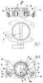
- Reference number 1 denotes a throttle valve assembly of an internal combustion engine.
- a throttle valve 3 is rotatably supported via the axis 2.
- this throttle valve is operated as is known, i.e. on the throttle valve axis 2, two sheaves 4 are fastened, which accommodate the cables.
- a return spring 5 which tends to move the throttle valve 3 into its closed position.
- the rope pulley 4 is supported when the throttle valve 3 is closed on a shoulder 6a of an actuating cylinder 6 which is rotatable coaxially to the throttle valve axis 2.
- This paragraph 6a is also referred to as the stop of the actuating cylinder 6, also referred to as the throttle valve actuator. If the actuating cylinder is thus rotated slightly in the direction of the arrow 7 in FIG. 2, the throttle valve 3 is opened slightly; a rotation against the direction of arrow 7 causes the throttle valve to close at least slightly.
- the idle control of the internal combustion engine can also be carried out by rotating the actuating cylinder 6.
- the moving punches 8a of two high-performance piezo-oxide actuators 8 act essentially tangentially on the wall of the actuating cylinder 6.
- Such so-called PXE actuators are offered by Philipps-Valvo and are able to perform deflections of up to 100 micrometers in the millisecond range.
- the moving pistons 8a of the actuators 8 are pressed against the wall of the actuating cylinder 6 by a compression spring 9 each.
- a driving pin 10 which can be acted upon by a lifting magnet 11 in such a way that when this lifting magnet 11 is excited, the plunger 8a of the actuator 8 is lifted off the wall of the actuating cylinder 6.
- the actuating cylinder 6 is thus rotated slightly according to arrow 7.
- This right-hand piezo actuator 8 is then acted on in the opposite direction, ie the plunger performs a micro movement in the opposite direction of the arrow 12.
- the right-hand piezo actuator 8 is then electrically acted upon again analogously to the first actuation, so that the plunger 8a again moves in the direction of the arrow 12.
- the described actuating device for the throttle valve 3, consisting of the high-performance piezo-oxide actuators 8 as the piezoelectric actuator and a so-called mit step transmission as the transmission element, can be structurally attached in a simple manner to a throttle valve connector 1 of an internal combustion engine. All that is required for this is the retaining bracket designated with the reference number 13.
- the space requirement of this actuating device is extremely small, moreover, as already explained at the beginning, this actuating device has the advantages of high precision and minimal time delay. Explicitly pointed out should be that with the help of such an actuating device not only the idle control can be realized on a throttle valve, but the entire actuation of the throttle valve can take place over the entire operating range of the internal combustion engine.
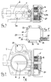
- the piezoelectric actuator is designed as a so-called piezo-hydraulic pressure cell 20, while the transmission element is essentially formed by a cylinder-piston unit 21.
- the same components as in Figures 1, 2 are also designated here with the same reference numerals.
- the piezohydraulic pressure cell 20 which is shown in detail in particular in FIG. 5, consists of a cube-shaped frame 22, the side surfaces of which have circular openings 23. Each opening 23 is covered by a piezo bimorph disk 24. This pressure cell is completely filled with a suitable hydraulic fluid.
- the piezo bimorph disks 24, which are also referred to as PXE bending elements (membranes), are described in more detail, for example, in Philipp's manual "Piezoxides - Properties and Applications" and have the property of changing their shape when subjected to electrical voltage, that a change in volume occurs.
- this change in pressure and volume is caused by the designed as a cylinder-piston unit 21 transfer member.
- the numerical values given in the paragraph above result in a positioning force of 9.3 N for a piston diameter of 2.2 mm and an achievable stroke of 10 mm. Since the piston of the cylinder-piston unit 21 acts on the stop of the throttle valve actuator or on the shoulder 6a of the actuating cylinder 6, the throttle valve can also be actuated by this, as desired, in particular for idling control.
- FIG. 5 shows support rings 26 arranged between the piezo bimorph discs 24 and the frame 22.
- the piezo bimorph discs 24 are soldered or glued to these support rings 26; the same connection technology is available between the support rings 26 and the frame 22.
- a bellows 27 which is completely against the sides thereof and thus also completely against the piezo bimorph disks 24 is also provided within this pressure cell 20.
- this embodiment shown is only a preferred embodiment; In addition, there are of course a variety of other designs possible.
Claims (7)
- Dispositif d'actionnement pour un système d'étranglement d'un moteur à combustion interne, en particulier pour la régulation de son ralenti, avec un organe de réglage piézo-électrique ou magnétostrictif qui vient en prise par un organe de transmission sur le système d'étranglement, dispositif d'actionnement caractérisé en ce que l'organe de réglage piézo-électrique ou magnétostrictif est constitué sous la forme d'une capsule métallique (20) qui est reliée de façon hydraulique à l'organe de transmission constitué sous la forme d'un vérin (21), et dont le volume hydraulique peut être modifié en commandant électriquement des éléments piézo-électriques ou magnétostrictifs (24).
- Dispositif d'actionnement selon la revendication 1, caractérisé en ce que les parois latérales de la capsule métallique piézo-hydraulique de forme sensiblement parallélépipédique (20) sont constituées par des disques piézo-bimorphes (24) fixés sur un cadre (22).
- Dispositif d'actionnement selon la revendication 2, caractérisé en ce que la capsule métallique piézo-hydraulique contient plusieurs chambres hydrauliques délimitées par des disques piézo-bimorphes se suivant les uns les autres.
- Dispositif d'actionnement selon la revendication 2 ou 3, caractérisé en ce que la capsule métallique piézo-hydraulique (20) est fixée en particulier par son cadre (22) sur l'ajutage (1) du clapet d'étranglement recevant le système d'étranglement (clapet d'étranglement 3).
- Dispositif d'actionnement pour un système d'étranglement d'un moteur à combustion interne, en particulier pour la régulation de son ralenti, avec un organe de réglage piézo-électrique ou magnétostrictif qui vient en prise par l'intermédiaire d'un organe de transmission sur le système d'étranglement, caractérisé en ce que l'organe de transmission est constitué sous la forme d'une transmission à pas de pèlerin actionnée par au moins un organe de réglage piézo-électrique ou magnétostrictif constitué comme un actionneur piézoxyde ou un actionneur magnétostrictif de force puissance.
- Dispositif d'actionnement selon la revendication 5, caractérisé en ce que, disposés de façon symétrique, on prévoit deux actionneurs piézoxydes (8) qui viennent en prise de façon sensiblement tangentielle sur un cylindre de réglage (6) disposé coaxialement par rapport à l'axe du clapet d'étranglement (2), actionneurs qui sont pressés contre la paroi du cylindre de réglage, en particulier par des ressorts de compression (9), et peuvent être soulevés du cylindre de réglage en particulier par des électro-aimants de levage.
- Dispositif d'actionnement selon la revendication 6, caractérisé en ce que la paroi du cylindre de levage (6) présente des stries qui s'étendent en particulier dans le sens de l'axe du cylindre.
Applications Claiming Priority (2)
| Application Number | Priority Date | Filing Date | Title |
|---|---|---|---|
| DE4224424 | 1992-07-24 | ||
| DE4224424A DE4224424C1 (de) | 1992-07-24 | 1992-07-24 | Betätigungsvorrichtung für eine Brennkraftmaschinen-Drosseleinrichtung |
Publications (2)
| Publication Number | Publication Date |
|---|---|
| EP0579932A1 EP0579932A1 (fr) | 1994-01-26 |
| EP0579932B1 true EP0579932B1 (fr) | 1995-07-05 |
Family
ID=6463975
Family Applications (1)
| Application Number | Title | Priority Date | Filing Date |
|---|---|---|---|
| EP93108635A Expired - Lifetime EP0579932B1 (fr) | 1992-07-24 | 1993-05-28 | Dispositif de commande de papillon de moteur à combustion interne |
Country Status (2)
| Country | Link |
|---|---|
| EP (1) | EP0579932B1 (fr) |
| DE (2) | DE4224424C1 (fr) |
Families Citing this family (3)
| Publication number | Priority date | Publication date | Assignee | Title |
|---|---|---|---|---|
| JP2000240474A (ja) * | 1999-02-24 | 2000-09-05 | Mikuni Corp | 内燃機関のスロットルバルブ制御装置 |
| KR100448806B1 (ko) * | 2002-05-17 | 2004-09-16 | 현대자동차주식회사 | 스로틀 밸브 제어 장치 및 그 방법 |
| US7159563B1 (en) * | 2005-10-28 | 2007-01-09 | Delphi Technologies, Inc. | Piezo electronic throttle control actuator |
Family Cites Families (5)
| Publication number | Priority date | Publication date | Assignee | Title |
|---|---|---|---|---|
| FR91906E (fr) * | 1965-09-08 | 1968-08-30 | Dispositif de commande pour les appareils de désintoxication des gaz d'échappement des moteurs à allumage commandé | |
| USRE32413E (en) * | 1981-04-15 | 1987-05-12 | Nissan Motor Company, Limited | Two-shift throttle control system for automotive internal combustion engine |
| JPH01203620A (ja) * | 1988-02-09 | 1989-08-16 | Kiyousan Denki Kk | エンジンのアイドル回転制御装置 |
| JP2690977B2 (ja) * | 1988-03-18 | 1997-12-17 | 株式会社日立製作所 | 内燃機関用電子制御式スロットルバルブ |
| DE3842397A1 (de) * | 1988-12-16 | 1990-06-21 | Audi Ag | Vorrichtung zum unterbrechen des kraftschlusses zwischen zwei bauteilen |
-
1992
- 1992-07-24 DE DE4224424A patent/DE4224424C1/de not_active Expired - Fee Related
-
1993
- 1993-05-28 EP EP93108635A patent/EP0579932B1/fr not_active Expired - Lifetime
- 1993-05-28 DE DE59300329T patent/DE59300329D1/de not_active Expired - Fee Related
Also Published As
| Publication number | Publication date |
|---|---|
| DE4224424C1 (de) | 1993-12-09 |
| EP0579932A1 (fr) | 1994-01-26 |
| DE59300329D1 (de) | 1995-08-10 |
Similar Documents
| Publication | Publication Date | Title |
|---|---|---|
| DE60223341T2 (de) | Direkt angetriebenes Pneumatikventil mit luftunterstütztem Rückhub | |
| DE102012214622A1 (de) | Aktoreinrichtung und Axialkolbenmaschine | |
| DE102010010801A1 (de) | Aktuator | |
| DE3329734C2 (fr) | ||
| DE2714430A1 (de) | Betaetigungsvorrichtung | |
| EP0579932B1 (fr) | Dispositif de commande de papillon de moteur à combustion interne | |
| EP0904495B1 (fr) | Dispositif a soupape, en particulier dispositif combine valve proportionnelle-distributeur | |
| DE69913287T2 (de) | Brennkraftmaschine mit elektromagnetischem Ventilantrieb | |
| EP1313970A1 (fr) | Dispositif pour actionner un embrayage | |
| WO2011038952A1 (fr) | Soupape présentant un sac magnétique | |
| EP2356705B1 (fr) | Entraînement universel électrique de piézomoteur | |
| WO2019086181A1 (fr) | Actionneur linéaire électrohydraulique | |
| DE10138741A1 (de) | Ventilhubverstellung für Verbrennungsmotoren | |
| DE19730052C1 (de) | Piezohydraulischer Antrieb | |
| DE10220928B4 (de) | Verfahren und Einrichtung zur steuerbaren Begrenzung des Hubs eines hydraulisch betätigten Zylinderventils | |
| DE19905626A1 (de) | Stellzylinder sowie Verfahren zum Einstellen eines Stellzylinders | |
| EP0218927B1 (fr) | Dispositif d'arrêt électromagnétique pour un moteur à combustion | |
| DE19858758C1 (de) | Vorrichtung und Verfahren zur Hubübertragung | |
| DE102016210975A1 (de) | Ventiltrieb für eine Brennkraftmaschine | |
| DE1589733C3 (de) | Elektromagnet für ein Ventil | |
| DE19719557A1 (de) | Ventileinrichtung, insbesondere kombinierte Proportional-Wegeventileinrichtung | |
| DE102021200979A1 (de) | Linearaktuator | |
| AT230160B (de) | Elektrohydraulisches Stellgerät | |
| DE102012214619A1 (de) | Aktoreinrichtung und Axialkolbenmaschine | |
| DE102016210711A1 (de) | Aktuatoranordnung |
Legal Events
| Date | Code | Title | Description |
|---|---|---|---|
| PUAI | Public reference made under article 153(3) epc to a published international application that has entered the european phase |
Free format text: ORIGINAL CODE: 0009012 |
|
| AK | Designated contracting states |
Kind code of ref document: A1 Designated state(s): DE FR GB IT |
|
| 17P | Request for examination filed |
Effective date: 19940214 |
|
| 17Q | First examination report despatched |
Effective date: 19941216 |
|
| GRAA | (expected) grant |
Free format text: ORIGINAL CODE: 0009210 |
|
| AK | Designated contracting states |
Kind code of ref document: B1 Designated state(s): DE FR GB IT |
|
| ET | Fr: translation filed | ||
| GBT | Gb: translation of ep patent filed (gb section 77(6)(a)/1977) |
Effective date: 19950704 |
|
| REF | Corresponds to: |
Ref document number: 59300329 Country of ref document: DE Date of ref document: 19950810 |
|
| ITF | It: translation for a ep patent filed |
Owner name: STUDIO JAUMANN |
|
| PLBE | No opposition filed within time limit |
Free format text: ORIGINAL CODE: 0009261 |
|
| STAA | Information on the status of an ep patent application or granted ep patent |
Free format text: STATUS: NO OPPOSITION FILED WITHIN TIME LIMIT |
|
| 26N | No opposition filed | ||
| PGFP | Annual fee paid to national office [announced via postgrant information from national office to epo] |
Ref country code: DE Payment date: 19980504 Year of fee payment: 6 |
|
| PGFP | Annual fee paid to national office [announced via postgrant information from national office to epo] |
Ref country code: GB Payment date: 19980526 Year of fee payment: 6 |
|
| PGFP | Annual fee paid to national office [announced via postgrant information from national office to epo] |
Ref country code: FR Payment date: 19980528 Year of fee payment: 6 |
|
| PG25 | Lapsed in a contracting state [announced via postgrant information from national office to epo] |
Ref country code: GB Free format text: LAPSE BECAUSE OF NON-PAYMENT OF DUE FEES Effective date: 19990528 |
|
| GBPC | Gb: european patent ceased through non-payment of renewal fee |
Effective date: 19990528 |
|
| PG25 | Lapsed in a contracting state [announced via postgrant information from national office to epo] |
Ref country code: FR Free format text: LAPSE BECAUSE OF NON-PAYMENT OF DUE FEES Effective date: 20000131 |
|
| PG25 | Lapsed in a contracting state [announced via postgrant information from national office to epo] |
Ref country code: DE Free format text: LAPSE BECAUSE OF NON-PAYMENT OF DUE FEES Effective date: 20000301 |
|
| REG | Reference to a national code |
Ref country code: FR Ref legal event code: ST |
|
| PG25 | Lapsed in a contracting state [announced via postgrant information from national office to epo] |
Ref country code: IT Free format text: LAPSE BECAUSE OF NON-PAYMENT OF DUE FEES;WARNING: LAPSES OF ITALIAN PATENTS WITH EFFECTIVE DATE BEFORE 2007 MAY HAVE OCCURRED AT ANY TIME BEFORE 2007. THE CORRECT EFFECTIVE DATE MAY BE DIFFERENT FROM THE ONE RECORDED. Effective date: 20050528 |