EP0578499B1 - Module de diode laser - Google Patents
Module de diode laser Download PDFInfo
- Publication number
- EP0578499B1 EP0578499B1 EP93305360A EP93305360A EP0578499B1 EP 0578499 B1 EP0578499 B1 EP 0578499B1 EP 93305360 A EP93305360 A EP 93305360A EP 93305360 A EP93305360 A EP 93305360A EP 0578499 B1 EP0578499 B1 EP 0578499B1
- Authority
- EP
- European Patent Office
- Prior art keywords
- laser diode
- lens holder
- lens
- base
- holder
- Prior art date
- Legal status (The legal status is an assumption and is not a legal conclusion. Google has not performed a legal analysis and makes no representation as to the accuracy of the status listed.)
- Expired - Lifetime
Links
Images


Classifications
-
- G—PHYSICS
- G06—COMPUTING; CALCULATING OR COUNTING
- G06K—GRAPHICAL DATA READING; PRESENTATION OF DATA; RECORD CARRIERS; HANDLING RECORD CARRIERS
- G06K7/00—Methods or arrangements for sensing record carriers, e.g. for reading patterns
- G06K7/10—Methods or arrangements for sensing record carriers, e.g. for reading patterns by electromagnetic radiation, e.g. optical sensing; by corpuscular radiation
- G06K7/10544—Methods or arrangements for sensing record carriers, e.g. for reading patterns by electromagnetic radiation, e.g. optical sensing; by corpuscular radiation by scanning of the records by radiation in the optical part of the electromagnetic spectrum
- G06K7/10554—Moving beam scanning
- G06K7/10594—Beam path
- G06K7/10603—Basic scanning using moving elements
- G06K7/10633—Basic scanning using moving elements by oscillation
- G06K7/10643—Activating means
- G06K7/10653—Activating means using flexible or piezoelectric means
-
- G—PHYSICS
- G06—COMPUTING; CALCULATING OR COUNTING
- G06K—GRAPHICAL DATA READING; PRESENTATION OF DATA; RECORD CARRIERS; HANDLING RECORD CARRIERS
- G06K7/00—Methods or arrangements for sensing record carriers, e.g. for reading patterns
- G06K7/10—Methods or arrangements for sensing record carriers, e.g. for reading patterns by electromagnetic radiation, e.g. optical sensing; by corpuscular radiation
- G06K7/10544—Methods or arrangements for sensing record carriers, e.g. for reading patterns by electromagnetic radiation, e.g. optical sensing; by corpuscular radiation by scanning of the records by radiation in the optical part of the electromagnetic spectrum
- G06K7/10554—Moving beam scanning
- G06K7/10594—Beam path
- G06K7/10603—Basic scanning using moving elements
- G06K7/10633—Basic scanning using moving elements by oscillation
- G06K7/10643—Activating means
-
- G—PHYSICS
- G02—OPTICS
- G02B—OPTICAL ELEMENTS, SYSTEMS OR APPARATUS
- G02B6/00—Light guides; Structural details of arrangements comprising light guides and other optical elements, e.g. couplings
- G02B6/24—Coupling light guides
- G02B6/42—Coupling light guides with opto-electronic elements
- G02B6/4201—Packages, e.g. shape, construction, internal or external details
- G02B6/4204—Packages, e.g. shape, construction, internal or external details the coupling comprising intermediate optical elements, e.g. lenses, holograms
Definitions
- the present invention generally relates to laser diode modules, and more particularly to a laser diode module suitably applied to a bar code reader in which a laser diode is used as a light source.
- a bar code reader that optically reads a bar code uses a semiconductor laser diode (hereinafter, simply referred to as a laser diode).
- a laser diode is combined with optical elements such as lenses, and a laser diode module made up of the laser diode and the optical elements is provided as a light source.
- a light emitted from the laser diode is optically processed by the optical elements of the laser diode module, and is projected onto a bar code via an optical scanning system outside of the laser diode module.
- the performance of the bar code reader greatly depends on the performance of the laser diode module.
- a complex adjustment mechanism is employed in the laser diode module in order to improve the performance thereof.
- such an adjustment mechanism is designed to adjust the positions of optical elements, such as lenses.
- a plurality of optical elements are used to improve the performance of the laser diode module.
- JP-A-63 316819 A different approach is described in JP-A-63 316819.
- a light beam scanning device is described that has a collimating lens that is tiltable about two axes to correct astigmatism.
- JP-A-2-282939 describes an optical pickup in which adjustment of a screw moves a collimating lens forward and backwards so that the collimating lens can be correctly positioned.
- a laser diode module including: a laser diode for emitting a laser beam; a lens; a base which holds the laser diode; and a lens holder which holds the lens so that a tilt angle of the lens with respect to an optical axis can be adjusted and which is mounted on the base; characterised by further including an adjustment means adapted to slide the laser diode and the lens with respect to each other along the optical axis so that the lens can be tilted and slid to obtain a minimum beam spot size.
- the base which holds the laser diode has a mounting surface
- the lens holder is slidably mounted on the mounting surface
- a mechanism is provided which tilts the lens holder with respect to the mounting surface of the base so that the lens is tilted with respect to the optical axis.
- the first lens holder may have a first through-hole in which the lens is placed.
- the second holder may have a second hole into which the first lens holder is inserted, and two third holes joined to the first through-hole and formed on respective sides of the first through hole.
- the laser beam emitted from the laser diode is propagated through one of the two third holes, a part of the second hole, the lens, a remaining part of the second hole, and the other one of the two third holes.
- a bar code reader 1 is made up of a laser diode module 2 functioning as a light source, an optical scanning system 4, a photodetector 9 and a processing circuit 10.
- a laser beam 3 emitted from the laser diode module 2 is oriented toward an item 6 and deflected as indicated by an arrow 5 by means of the optical scanning system 4, which comprises, for example, a polygon mirror and mirrors.
- a bar code 7 formed on the item 6 is scanned by the deflected laser beam 3.
- the deflected laser beam 3 is reflected by the bar code 7 and the intensity thereof is modulated (amplitude modulation).
- a reflected light 8 is then detected by the photodetector 9, which outputs a corresponding electric signal to the processing circuit 10.
- This circuit 10 performs a predetermined operation on the received electric signal, and generates bar-code read data.
- the laser diode module 2 includes a laser diode and an optical element.
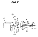
- Fig. 2 shows an optical character of a laser diode of the laser diode module 2.
- Fig. 2 shows a laser diode 11 used in the laser diode module 2.
- the laser diode 11 has an astigmatic difference 'a' normally equal to 10 ⁇ m.
- the astigmatic difference of normal laser diodes ranges from 5 ⁇ m to 15 ⁇ m.
- Due to the astigmatic difference, a far-field pattern 13 of a laser beam 12 emitted from the laser diode 11 is of an oval shape having a long axis 14 in the vertical direction and a short axis 15 in the horizontal direction.
- the focal point of a laser beam component 12 V in the vertical direction in a vertical plane is defined as a vertical-direction focal point F V
- the focal point of a laser beam component 12 H in the horizontal direction in a horizontal plane is defined as a horizontal-direction focal point F H .
- a distance 'b' between the vertical-direction focal point F V and the horizontal-direction focal point F H ranges within ⁇ a few of tens of micron.
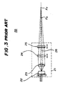
- Fig. 3 shows a conventional laser diode module 20 made up of a laser diode 22, a collimating lens 23, a cylindrical lens 24, a cylindrical lens 25, these elements being arranged on an optical axis 26.
- the cylindrical lens 24 functions to converge the laser beam emitted from the laser diode 22 in the vertical direction.
- the cylindrical lens 25 functions to converge the laser beam in the horizontal direction.
- the lenses 24 and 25 are provided so that the positions thereof are independently adjusted along the optical axis 26.
- the position of the horizontal-direction focal point F H can be adjusted by adjusting the position of the lens 25 along the optical axis 26.
- the position of the vertical-direction focal point F V can be adjusted by adjusting the position of the lens 24 along the optical axis 26.
- the conventional laser diode shown in Fig. 3 has a disadvantage in that the module 20 is of a large size and is expensive due to use of the three lenses 23, 24 and 25.
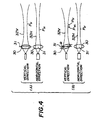
- Fig. 4-(A) and Fig. 4-(B) the inventors attempted to tilt a lens 30 with respect to a horizontal axis 31. At this time, the inventors observed that the position P H of a beam waist of a beam 32 H in the horizontal direction 32 H did not change, while the position P V of a beam waist of a beam 32 V in the vertical direction 32 V changed from an original position P V to a position P V1 towards the lens 30.
- a tilt angle ⁇ of the lens 30 and the degree of positional variation in the beam waist P V have a relationship indicated by a line I in Fig. 5. It can be seen from Fig. 5 that the degree of positional variation in the beam waist P V is increased as the tilt angle ⁇ is increased within a certain range.
- the present invention has a mechanism for tilting a lens.
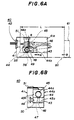
- Figs. 6A, 6B and 6C are diagrams of a laser diode module 40 according to a first embodiment of the present invention.
- the laser diode module 40 includes a base 41 having a first vertical portion 43c to which a laser diode 42 is fixed. Further, the base 41 has a lens holder mounting part 43, which includes a horizontal lens holder mounting portion 43a and a second vertical portion 43b. The surfaces of the portions 43a and 43b are high-precision flat surfaces.
- a lens holder 44 is of a substantially L-shape, and has a vertical portion 44a and a horizontal portion 44b.
- a lens 45 is fixed to the vertical portion 44a.
- a through female screw 46 is vertically formed at an end part of the horizontal portion 44b of the lens holder 44.
- An adjustment male screw 47 for pivoting the lens holder 44 engages the female screw 46.
- An end portion of the adjustment male screw 47 can project from the lower surface of the horizontal portion 44b of the lens holder 44.
- a hole 48 that is long in the horizontal direction is formed in a vertical wall 41a of the base 41.
- a male screw 49 is inserted into the long hole 48 and is engaged with a female screw 50 formed in a root portion at which the vertical portion 44a of the lens holder 44 and the horizontal portion 44b thereof are connected to each other.
- a leaf spring 51 presses the lens holder 44 against the lens holder mounting portion 43a of the base 41.
- An ajustment operation of the lens holder 44 is performed as follows. As shown in Fig. 6A, an optical bench 60 and a beam spot measuring instrument 61 are used to perform the adjustment operation. At the first step of the adjustment operation, the base 41 and the measuring instrument 61 are placed on the optical bench 60 so that the distance between the laser diode 42 and the measuring instrument 61 is equal to a predetermined distance L.
- the horizontal-direction focal point is adjusted as follows.
- the male screw 49 is turned (loosed) in a state in which the screw 47 does not project from the lower surface of the horizontal portion 44b of the lens holder 44.
- the male screw 49 is turned in a state in which the lens 45 is not tilted.
- An output signal of the measuring instrument 61 is monitored while the lens holder 44 is made to slide on the lens holder mounting portion 43a in a direction indicated by a two-headed arrow A, as shown in Fig. 6A. In this manner, the position of the lens holder 44 at which a minimum beam spot size can be obtained is identified. Therefore, the screw 49 is secured so that the lens holder 44 is provisionally fixed to the base 41.
- the vertical-direction focal point is adjusted as follows.
- the measuring instrument 61 is moved in a direction indicated by a single-headed arrow B, as shown in Fig. 6A.
- the screw 47 is turned so that it downwards projects from the horizontal portion 44b of the lens holder 44.
- the screw 47 depresses the lens holder mounting portion 43a, so that the lens holder 44 is turned as indicated by an arrow C shown in Fig. 6A.
- an angle ⁇ between the vertical direction and the vertical surface of the vertical portion 44a of the lens holder 44 is formed. That is, the lens 45 is tilted by the angle ⁇ in the counterclockwise direction.
- the lens 45 is tilted by tilting the lens holder 44 in the above-mentioned manner and hence no stress is exerted on the lens 45.
- the screw 47 is turned in order to identify a tilted position of the lens holder 44 at which a minimum beam spot size can be obtained.
- the screw 49 is secured to fix the lens holder 44 to the base 41.
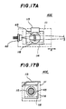
- the lens holder 44 has a chamfered corner 55.
- the lens holder 44 is caused to pivot about an end 56 of the chamfered corner 55 in the direction indicated by the arrow C.
- the chamfered corner 55 is formed so that the end 56 is located just below the female screw 50. If the chamfered portion 55 is not formed, as shown in Fig. 7B, the position of the female screw 50 will move greatly in the vertical direction, and the possible tilt angle ⁇ will be limited to a narrow range due to the relation with the long hole 48.
- the chamfered corner 55 causes the female screw 50 to be moved, as shown in Fig. 7A. It will be seen from Fig. 7A that the position of the female screw 50 does not move greatly in the vertical direction. With the above structure, it is possible to cause the lens holder 44 to pivot about the end 56 up to approximately 10° and to facilitate the adjustment of the vertical-direction focal point.
- the leaf spring 51 presses the lens holder 44 against the lens holder mounting surface 43a.
- the lens holder 44 can be made to pivot about the end 56 in the state where the end 56 is in contact with the lens holder mounting surface 43a of the base 41.
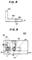
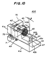
- the laser diode module 40A shown in Figs. 9 and 10 has a base 41A having a hole 71 which is formed in the vertical portion 41 of the base 41A and is long in the horizontal direction A.
- the lens holder 44 is rotatable in the direction indicated by the arrow C.
- a laser diode holder 70 is provided so that it can slide on the lens holder mounting surface 43a in the direction A.
- the base 41A shown in Figs. 9 and 10 does not have the vertical portion 43c of the base 41 shown in Figs. 6A through 6C.
- the laser diode holder 70 can be fixed at a desired position by means of a male screw 72, which is inserted into the long hole 71 and is engaged with a female screw formed in the laser diode holder 70.
- the horizontal-direction focal point can be adjusted so that the lens holder 70 is moved in the direction A.
- the vertical-direction focal point can be adjusted by means of the screw 47 in the same manner as that in the first embodiment of the present invention.
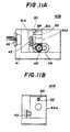
- FIG. 11A, 11B and 11C A description will now be given, with reference to Figs. 11A, 11B and 11C, of a laser diode module 40B according to a third embodiment of the present invention.
- Figs. 11A through 11C parts that are the same as those shown in the previously described figures are given the same reference numbers.
- a lens holder 44A to be used instead of the aforementioned lens holder 44 has a first vertical plate portion 81a and a second vertical portion 81b.
- the lens holder 44A is an integrally formed member and, the portions 81a and 81b thereof are integrally formed and are opposite to each other via a slit 80.
- the lens 45 is fixed to the first vertical plate portion 81a.
- the second vertical portion 81b has a through hole 80b extending in the horizontal direction and allows the laser beam via the lens 45 to pass through the through hole 80b.
- a through female screw 84 is formed in the vertical portion 81b and is located above the through hole 80b.
- a male screw 82 which engages the female screw 84, passes through the slit 80 and can come in contact with an upper portion of the vertical plate portion 81a.
- By turning the male screw 82 it gradually presses the vertical plate portion 81a, which is gradually bent and tilted, so that the lens 45 is tilted by the angle ⁇ .
- the slit 80 makes the vertical plate portion 81a flexible. In this manner, the vertical-direction focal point can be adjusted.
- the horizontal-direction focal point can be adjusted in the same manner as that of the first embodiment of the present invention. That is, the lens holder 44A is slidable on the lens holder mounting surface 43a, and is fixed at a position where a minimum beam spot size can be obtained.
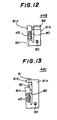
- Fig. 12 is a diagram of a first variation 44B of the lens holder 44A used in the third embodiment of the present invention.
- a groove 90 is formed in an outer root portion of the vertical plate portion 81a. The groove 90 facilitate the degree of flexibility of the vertical plate portion 81a.
- Fig. 13 is a diagram of a second variation 44C of the lens holder 44A used in the third embodiment of the present invention.
- the vertical portion 81b has a horizontal projection 81b' located above the slit 80.
- a male screw 91 vertically penetrates the horizontal portion 81b' and projects therefrom.
- a female screw engaging the male screw 91 is formed in the horizontal projection 81b'.
- a wedge 92 is depressed by the male screw 91, so that the wedge 92 is forced to be inserted into the slit 80.
- the adjustment operation can be performed from the upper side of the laser diode module without interrupting the laser beam emitted via the lens 45.
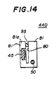
- Fig. 14 is a diagram of a third variation 44D of the lens holder 44A used in the third embodiment of the present invention.
- a rod 93 having an oval cross-section is rotatably provided in the slit 80. By rotating the rod 93, the vertical plate portion 81a is bent, so that the lens 45 is tilted.
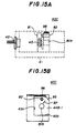
- FIGs. 15A, 15B and 15C of a laser diode module 40C according to a fourth embodiment of the present invention.
- Figs. 15A through 15C parts that are the same as those shown in the previously described figures are given the same reference numbers.
- a lens holder 44B-1 includes the vertical projections 81a and 81b.
- a slope portion 95 is formed in a corner of the vertical portion 81b.
- a leaf spring 96 having an end embedded in the vertical portion 41a of the base 41 engages the slope portion 95 of the vertical portion 81b.
- the leaf spring 96 urges the lens holder 44B-1 in a direction indicated by an arrow 97 shown in Fig. 15B.
- the lens holder 44B-1 is pressed against the lens holder mounting surface 43a and the vertical surface 43b.
- the lens holder 44B-1 can be fastened to the base 41 by means of an adhesive or the like.
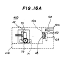
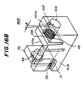
- FIGs. 16A and 16B are diagrams of a laser diode module 40D according to a fifth embodiment of the present invention.
- a base 41B has a first vertical plate portion 101a and a second vertical portion 101b, these portions being spaced apart from each other via a slit 100.
- the lens 45 is fixed to the vertical portion 101a.
- a male screw 102 engages a female screw formed in the vertical portion 101b and projects therefrom.
- a through hole 103 is formed in the vertical portion 101b so that the laser beam passing through the lens 45 is allowed to pass. The screw 102 comes into contact with an upper portion of the vertical portion 101a.
- the vertical portion 101a is bent and tilted, so that the lens 45 can be tilted.
- the laser diode 42 is held by the laser diode holder 70 used in the second embodiment of the present invention. Since the screw 102 for the adjustment is provided in the base 41B fixed to the optical bench, it is easy to operate the screw 102.
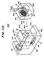
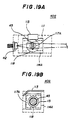
- the laser diode module 40E includes a base 111 having a first vertical portion 111a, a second vertical portion 111b, and a holder mounting surface 111c.
- the first and second vertical portions 111a and 111b are provided so that these portions form a right angle.
- the laser diode 42 is fixed to the second vertical portion 111b.
- a holder 114 is mounted on the holder mounting surface 111c, and is slidable thereon.
- a leaf spring 113 fixes the holder 114 on the holder mounting surface 111C in a state in which the holder 114 is in contact with the first vertical portion 111a of the base 111.
- One end of the leaf spring 113 is embedded in the first vertical portion 111a, and the other end engages an edge of the holder 114.
- the holder 114 has a large cylindrical through hole 117, and two small cylindrical holes 115 and 116.
- the holes 115 and 116 are located on respective sides of the through hole 117 and are connected to the through hole 117.
- the laser beam emitted from the laser diode 42 enters into the hole 116.
- the through hole 117 accommodates a lens holder 118 having a cylindrical shape and almost the same width as that of the holder 114.
- the lens holder 118 has a through hole 120, which is integrated with the holes 115 and 116 when the lens holder 118 is inserted into the holder 114 and placed in a position.
- the lens 45 is located in the through hole 120 of the lens holder 118.
- the laser beam from the hole 116 passes through the lens 45 and is emitted through the hole 115.
- a straight groove 119 is formed on a front surface of the lens holder 118.
- FIGs. 18A, 18B and 18C of a first variation 40F of the laser diode module 40E according to the sixth embodiment of the present invention.
- Figs. 18A through 18C parts that are the same as those shown in Figs. 17A through 17C are given the same reference numbers.
- the laser diode module 40F shown in Figs. 18A through 18C has a leaf spring 126 fastened to the holder 114 by means of a male screw 127.
- the leaf spring 126 presses the lens holder 118 against the first vertical portion 111a of the base 111. Thereby, a deviation of the lens holder 118 and the lens 45 in the direction perpendicular to the optical axis of the laser diode 42 can be prevented.
- Figs. 19A, 19B and 19C illustrate a second variation 40G of the laser diode module 40E according to the sixth embodiment of the present invention.
- Figs. 19A through 19C parts that are the same as those shown in the previously described figures are given the same reference numbers.
- the laser diode module 40G has a holder 114A having a through hole 117A and the aforementioned holes 115 and 116.
- the lens holder 118 is inserted into the through hole 117A from the side of the holder 114A which is to come into contact with the first vertical portion 111a of the base 111.
- the diameter of the through hole 117A on the outside thereof is less than the diameter of the lens holder 118.
- a circular edge portion of the lens holder 118 comes into contact with an inner wall of the through hole 117A of the holder 114A.
- the leaf spring 113 presses the holder 114A against the first vertical portion 111a of the base 111 in such a state in which an end surface of the lens holder 118 opposite to the groove is in pressure contact with the first vertical portion 111a of the base 111.
- the vertical-direction focal point can be adjusted by turning the lens holder 118 by means of an instrument.
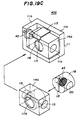
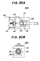
- FIGs. 20A, 20B and 20C of a third variation 40H of the laser diode module 40E according to the sixth embodiment of the present invention.
- Figs. 20A, 20B and 20C parts that are the same as those shown in the previously described figures are given the same reference numbers.
- the laser diode module 40H shown in Figs. 20A, 20B and 20C has a base 131 having a hole 136 into which the lens holder 118 is inserted.
- a hole 132 is joined to the hole 120 of the lens holder 118 when the lens holder 118 is inserted into the hole 136 and placed in a position.
- a hole 133 is formed in the base 131 so that it receives the laser beam emitted from the laser diode 42.
- the base 131 has a laser diode holder accommodating space defined by a vertical portion 131a and a laser diode holder mounting surface 131b.
- a block-shaped laser diode holder 141 which is slidable on the mounting surface 131b in the direction A, holds the laser diode 42.
- a leaf spring 135 having an end embedded in the vertical portion 131a of the base 131 engages an edge of the holder 141 and presses it against the vertical portion 131a.
- the horizontal-direction focal point can be adjusted by moving the laser diode holder 141 in the direction A.
- the vertical-distance focal point can be adjusted by turning the lens holder 118.
Claims (25)
- Module de diode laser incluant :caractérisé en ce qu'il comprend en outre un moyen (48, 49, 50) de réglage apte à faire coulisser la diode laser (42) et la lentille (45) l'une par rapport à l'autre suivant l'axe optique de façon à pouvoir incliner et faire coulisser la lentille pour obtenir une taille minimale de point lumineux de faisceau.une diode laser (42) destinée à émettre un faisceau laser ;une lentille (45) ;une base (41) qui maintient la diode laser; etune monture (44) de lentille qui porte la lentille de façon à pouvoir régler un angle d'inclinaison de la lentille par rapport à un axe optique, et qui est montée sur la base (41) ;
- Module de diode laser selon la revendication 1, dans lequel la base comporte une surface (43a) de montage, et dans lequel la monture (44) de lentille est montée de façon coulissante sur la surface de montage.
- Module de diode laser selon la revendication 2, comprenant en outre un mécanisme (47, 49) destiné à incliner la monture (44) de lentille par rapport à la surface (43a) de montage de la base (41) de façon à incliner la lentille (45) par rapport à l'axe optique.
- Module de diode laser selon la revendication 3, dans lequel ledit mécanisme comprend :une première vis (49) maintenant de façon mobile en rotation la monture (44) de lentille montée sur la surface (43a) de montage de la base (41) ; etune seconde vis (47) pénétrant dans la monture (44) de lentille et ayant une extrémité qui fait saillie de la monture (44) de lentille et qui vient en contact avec la surface (43a) de montage de la base.
- Module de diode laser selon la revendication 3, dans lequel ledit mécanisme comprend :une première vis (49) maintenant de façon mobile en rotation la monture de lentille montée sur la surface de montage de la base ; etune seconde vis pénétrant dans la base et ayant une extrémité qui fait saillie de la surface de montage de la base et qui vient en contact avec la monture de lentille.
- Module de diode laser selon la revendication 3, comprenant en outre un ressort à lame (51) supporté par la base (41) et en prise avec la monture (44) de lentille;ledit ressort à lame (51) poussant la monture (44) de lentille contre la base (41).
- Module de diode laser selon la revendication 3, dans lequel ladite base (41) comporte une partie fixe (35) maintenant la diode laser.
- Module de diode laser selon la revendication 4 ;dans lequel la base (41) comporte un trou (48) dans lequel s'introduit la première vis (49) ; etdans lequel le trou (48) a une longueur suffisamment longue pour déplacer la monture (44) de lentille sur la surface (43a) de montage de la base (41).
- Module de diode laser selon l'une quelconque des revendications précédentes ;dans lequel la base (41) comporte une surface (43a) de montage ;dans lequel le module de diode laser comporte une monture (70) de diode laser qui maintient la diode laser (42) ; etdans lequel la monture (70) de diode laser est montée de façon coulissante sur la surface (43a) de montage de la base (41).
- Module de diode laser selon la revendication 9, comprenant en outre un mécanisme (47, 49) qui incline la monture (44) de lentille par rapport à la surface (43a) de montage de la base (41) de façon à incliner la lentille (45) par rapport à l'axe optique.
- Module de diode laser selon la revendication 1, où la monture de lentille comporte une première partie (81a) et une seconde partie (81b) de l'autre côté d'une fente (80) par rapport à la première partie (81a); etoù il est prévu une vis (82) passant à travers la seconde partie (81b) et venant en contact avec la première partie (81a) en passant par la fente (80) ;dans lequel la première partie (81a) de la monture (44) de lentille maintient la lentille (45) ; etdans lequel la première partie de la monture (44) de lentille fléchit sous l'effet de la rotation de la vis (82) de façon à pouvoir régler l'angle d'inclinaison de la lentille (45) par rapport à l'axe optique suivant lequel se propage le faisceau laser.
- Module de diode laser selon la revendication 11, dans lequel la première partie (81a) de la monture de lentille possède une rainure facilitant la flexion de la première partie.
- Module de diode laser selon la revendication 1, où la monture (44) de lentille comporte :une première partie (81a) et une seconde partie (81b) de l'autre côté d'une fente (80) par rapport à la première partie (81a), la seconde partie comportant une saillie (81b) située au-dessus de la fente (80) ;un coin (92) s'engageant dans la fente (80) ; etune vis (91) passant à travers la saillie (81b) de la seconde partie et venant en contact avec le coin (92) ; etoù le module comprend en outre une base qui maintient la diode laser;dans lequel la première partie (81a) de la monture de lentille maintient la lentille (45) ; etdans lequel la première partie (81a) de la monture de lentille fléchit sous l'effet de la rotation de la vis (91) de façon à pouvoir régler l'angle d'inclinaison de la lentille (45) par rapport à l'axe optique.
- Module de diode laser selon la revendication 1, où la monture (44) de lentille comporte une première partie (81a) et une seconde partie (81b) de l'autre côté d'une fente (80) par rapport à la première partie ; etune tige (93) disposée dans la fente (80) et venant en contact avec les première et seconde parties (81a, 81b), la tige (93) ayant une section transversale ovale ; etoù le module comprend en outre une base qui maintient la diode laser ;dans lequel la première partie (81a) de la monture de lentille maintient la lentille (45) ; etdans lequel la première partie (81a) de la monture de lentille fléchit sous l'effet de la rotation de la tige (93) de façon à pouvoir régler l'angle d'inclinaison de la lentille (45) par rapport à l'axe optique suivant lequel se propage le faisceau laser.
- Module de diode laser selon la revendication 11, comprenant en outre un ressort à lame (96) supporté par la base (41) et en prise avec la monture (44) de lentille ;ledit ressort à lame (96) poussant la monture de lentille contre la base (41).
- Module de diode laser selon la revendication 15 ;dans lequel la base (41) comprend une partie verticale ;dans lequel la monture (44) de lentille possède une partie en pente (95) ; etdans lequel le ressort à lame (96) possède une partie recourbée coopérant avec la partie en pente (95) de la monture (44) de lentille de façon à pousser la monture (44) de lentille contre la partie verticale de la monture de lentille et contre sa surface de montage (43b).
- Module de diode laser selon la revendication 1 ;dans lequel la base (41) comporte une surface (43a) de montage ; etdans lequel il est prévu une monture (70) de diode laser qui maintient la diode laser (42) et qui est montée de façon coulissante sur la surface (43a) de montage de la base.
- Module de diode laser selon la revendication 17 ;dans lequel la base comporte une première partie (101a) et une seconde partie (101b) en face de la première partie de l'autre côté d'une fente (100);dans lequel le module de diode laser comprend une vis (102) passant à travers la seconde partie (101b) et venant en contact avec la première partie (101a) en passant par la fente (100);dans lequel la première partie (101a) de la base maintient la lentille (45) ; etdans lequel la première partie (101a) de la base fléchit sous l'effet de la rotation de la vis (102) de façon à pouvoir régler l'angle d'inclinaison de la lentille (45) par rapport à l'axe optique suivant lequel se propage le faisceau laser.
- Module de diode laser selon la revendication 1, où :
la base (41) comporte une surface de montage ; le module comprenant en outre :une seconde monture (114) montée de façon coulissante sur la surface de montage de la base (41) ;dans lequel la première monture (118) de lentille comporte un premier trou traversant (120) dans lequel est placée la lentille (45) ;dans lequel la seconde monture (114) comporte un deuxième trou (117) dans lequel s'introduit la première monture (118) de lentille, et deux troisièmes trous (115, 116) reliés au premier trou traversant (117) et formés des côtés respectifs du premier trou traversant (117); etdans lequel le faisceau laser émis par la diode laser (42) se propage à travers l'un des deux troisièmes trous (116), une partie du second trou (117), la lentille (45), une partie restante du second trou (117), et l'autre des deux troisièmes trous (115). - Module de diode laser selon la revendication 19 ;dans lequel la première monture (118) de lentille a une forme cylindrique ;dans lequel le second trou (117) a une forme cylindrique correspondant à la forme cylindrique de la première monture (118) de lentille ; etdans lequel la première monture (118) de lentille possède une rainure (119) dans laquelle on doit introduire un instrument pour faire tourner la première monture (118) de lentille.
- Module de diode laser selon la revendication 19, comprenant en outre un ressort à lame (113) ayant une première extrémité fixée à la base (41), et une seconde extrémité coopérant avec la seconde monture (114), de façon à pousser la seconde monture (114) contre la base (41).
- Module de diode laser selon la revendication 19, comprenant en outre un ressort à lame (176) possédant une première extrémité (127) fixée à la seconde monture (114), et une seconde extrémité coopérant avec la première monture (118) de lentille, de façon à pousser la première monture (118) de lentille contre la base.
- Module de diode laser selon la revendication 19, dans lequel une extrémité du premier trou traversant (117) a un premier diamètre plus petit qu'un second diamètre de la première monture (118) de lentille, de façon que la première monture (118) de lentille vienne en contact avec une paroi intérieure du premier trou traversant définissant le premier diamètre.
- Module de diode laser selon la revendication 1, comprenant en outre :une monture (141) de diode laser qui maintient la diode laser (42) et qui est montée de manière coulissante sur la surface de montage de la base (131) ;dans lequel la base possède une surface (131) de montage, un premier trou (136) et deux seconds trous (132) reliés au premier trou (136) et formés des côtés respectifs du premier trou ;dans lequel la monture (118) de lentille est introduite dans le premier trou ;dans lequel la monture (118) de lentille comporte un troisième trou (120) dans lequel est placée la lentille ; etdans lequel le faisceau laser émis depuis la diode laser (42) se propage à travers l'un des deux seconds trous (132), une partie du troisième trou (120), la lentille (45), une partie restante du troisième trou (120), et l'autre des deux seconds trous (132).
- Module de diode laser selon la revendication 24 ;dans lequel la monture (118) de lentille a une forme cylindrique ;dans lequel le premier trou (136) a une forme cylindrique correspondant à la forme cylindrique de la première monture (118) de lentille ; etdans lequel la monture (118) de lentille comporte une rainure (119) dans laquelle on doit monter un instrument destiné à faire tourner la monture (118) de lentille.
Applications Claiming Priority (3)
| Application Number | Priority Date | Filing Date | Title |
|---|---|---|---|
| JP18396892 | 1992-07-10 | ||
| JP183968/92 | 1992-07-10 | ||
| JP18396892 | 1992-07-10 |
Publications (3)
| Publication Number | Publication Date |
|---|---|
| EP0578499A2 EP0578499A2 (fr) | 1994-01-12 |
| EP0578499A3 EP0578499A3 (fr) | 1994-08-03 |
| EP0578499B1 true EP0578499B1 (fr) | 1999-12-01 |
Family
ID=16144979
Family Applications (1)
| Application Number | Title | Priority Date | Filing Date |
|---|---|---|---|
| EP93305360A Expired - Lifetime EP0578499B1 (fr) | 1992-07-10 | 1993-07-08 | Module de diode laser |
Country Status (4)
| Country | Link |
|---|---|
| US (3) | US5659432A (fr) |
| EP (1) | EP0578499B1 (fr) |
| KR (1) | KR940006320A (fr) |
| DE (1) | DE69327139T2 (fr) |
Families Citing this family (20)
| Publication number | Priority date | Publication date | Assignee | Title |
|---|---|---|---|---|
| US5625483A (en) * | 1990-05-29 | 1997-04-29 | Symbol Technologies, Inc. | Integrated light source and scanning element implemented on a semiconductor or electro-optical substrate |
| JP3489323B2 (ja) * | 1996-03-25 | 2004-01-19 | 三菱電機株式会社 | レーザダイオードモジユール、集光部品並びに光結合方法 |
| US6011577A (en) * | 1997-06-30 | 2000-01-04 | Polaroid Corporation | Modular optical print head assembly |
| JPH11305152A (ja) * | 1998-04-21 | 1999-11-05 | Asahi Optical Co Ltd | 走査光学装置 |
| JP3621850B2 (ja) * | 1999-09-07 | 2005-02-16 | 株式会社三協精機製作所 | 光ピックアップ装置 |
| US6426840B1 (en) * | 2001-02-23 | 2002-07-30 | 3D Systems, Inc. | Electronic spot light control |
| DE10219529B4 (de) * | 2002-05-02 | 2004-05-06 | Leuze Electronic Gmbh + Co Kg | Optischer Sensor |
| EP1561140A1 (fr) * | 2002-11-11 | 2005-08-10 | Cube Optics AG | Element de support destine au montage d'elements optiques et procede de fabrication dudit element de support |
| US7151557B2 (en) * | 2004-03-19 | 2006-12-19 | Lexmark International, Inc. | Collimation assembly for adjusting laser light sources in a multi-beamed laser scanning unit |
| GB0514493D0 (en) * | 2005-07-14 | 2005-08-17 | Point Source Ltd | Optical assembly |
| JP4306652B2 (ja) * | 2005-07-15 | 2009-08-05 | 船井電機株式会社 | 光ピックアップ装置 |
| JP2008090878A (ja) * | 2006-09-29 | 2008-04-17 | Funai Electric Co Ltd | 光ピックアップ装置 |
| JP4989302B2 (ja) * | 2007-05-10 | 2012-08-01 | Hoya株式会社 | 光ピックアップ光学系組付方法 |
| US7692882B2 (en) * | 2007-07-12 | 2010-04-06 | Lexmark International, Inc. | Laser diode and lens assemblies |
| KR101461959B1 (ko) * | 2008-07-01 | 2014-11-14 | 엘지전자 주식회사 | 스캐닝 디스플레이 |
| US8363083B2 (en) * | 2009-07-08 | 2013-01-29 | Brother Kogyo Kabushiki Kaisha | Light source device having holding member for holding light-emitting element and coupling lens for use in optical scanner |
| US8366298B2 (en) | 2010-08-24 | 2013-02-05 | Idexx Laboratories, Inc. | Laser diode mounting system |
| JP5616471B2 (ja) | 2013-03-05 | 2014-10-29 | 株式会社フジクラ | 半導体レーザモジュール及びその製造方法 |
| RU2678962C1 (ru) * | 2014-03-06 | 2019-02-04 | Сони Корпорейшн | Оптический разъем, кабель и устройство оптической связи |
| KR102136722B1 (ko) * | 2018-01-23 | 2020-07-23 | 전자부품연구원 | 송광 모듈 및 그를 갖는 스캐닝 라이다 |
Family Cites Families (17)
| Publication number | Priority date | Publication date | Assignee | Title |
|---|---|---|---|---|
| JPS59146013A (ja) * | 1983-12-23 | 1984-08-21 | Sony Corp | 光学装置 |
| JPS60153560A (ja) * | 1984-01-20 | 1985-08-13 | Matsushita Electric Ind Co Ltd | 文字列処理装置 |
| JPS60241013A (ja) * | 1984-05-16 | 1985-11-29 | Matsushita Electric Ind Co Ltd | 光ピツクアツプ |
| JPH0648543B2 (ja) * | 1985-12-04 | 1994-06-22 | 三菱電機株式会社 | 光学ヘツド装置 |
| CA1319194C (fr) * | 1986-07-28 | 1993-06-15 | Hideaki Satou | Detecteur d'erreurs a focalisation et dispositif de lecture de donnees optique incorporant ce detecteur |
| US4762395A (en) * | 1986-09-02 | 1988-08-09 | Amp Incorporated | Lens assembly for optical coupling with a semiconductor laser |
| JP2647091B2 (ja) * | 1987-06-19 | 1997-08-27 | 富士写真フイルム株式会社 | レーザビーム走査装置 |
| JP2679990B2 (ja) * | 1987-06-19 | 1997-11-19 | 富士写真フイルム株式会社 | 半導体レーザ光学装置 |
| US4831185A (en) * | 1987-12-18 | 1989-05-16 | Hoffmann-La Roche Inc. | Asymmetric synthesis of natural vitamin E |
| JPH0225810A (ja) * | 1988-07-15 | 1990-01-29 | Hitachi Ltd | 光電子装置 |
| JPH02162787A (ja) * | 1988-12-16 | 1990-06-22 | Foster Electric Co Ltd | 半導体レーザ装置 |
| JPH02282939A (ja) * | 1989-04-25 | 1990-11-20 | Seiko Epson Corp | 光学ピックアップ |
| JPH03179420A (ja) * | 1989-12-08 | 1991-08-05 | Toshiba Corp | 光学装置 |
| US5237457A (en) * | 1990-10-04 | 1993-08-17 | Asahi Kogaku Kogyo Kabushiki Kaisha | Apparatus for adjusting an optical axis including a laser beam source and a beam shaping prism |
| US5239414A (en) * | 1991-05-30 | 1993-08-24 | General Electric Company | Laser astigmatism compensation |
| JP3027649B2 (ja) * | 1992-02-28 | 2000-04-04 | アンリツ株式会社 | 光半導体素子モジュール |
| US5333145A (en) * | 1992-08-20 | 1994-07-26 | Fuji Photo Film Co., Ltd. | Solid laser |
-
1993
- 1993-07-08 EP EP93305360A patent/EP0578499B1/fr not_active Expired - Lifetime
- 1993-07-08 DE DE69327139T patent/DE69327139T2/de not_active Expired - Lifetime
- 1993-07-09 KR KR1019930012921A patent/KR940006320A/ko not_active Application Discontinuation
-
1995
- 1995-06-07 US US08/478,672 patent/US5659432A/en not_active Expired - Lifetime
- 1995-06-07 US US08/475,506 patent/US5633761A/en not_active Expired - Lifetime
-
1996
- 1996-09-26 US US08/718,651 patent/US5689378A/en not_active Expired - Lifetime
Also Published As
| Publication number | Publication date |
|---|---|
| DE69327139T2 (de) | 2000-04-06 |
| EP0578499A3 (fr) | 1994-08-03 |
| EP0578499A2 (fr) | 1994-01-12 |
| US5689378A (en) | 1997-11-18 |
| US5633761A (en) | 1997-05-27 |
| US5659432A (en) | 1997-08-19 |
| DE69327139D1 (de) | 2000-01-05 |
| KR940006320A (ko) | 1994-03-23 |
Similar Documents
| Publication | Publication Date | Title |
|---|---|---|
| EP0578499B1 (fr) | Module de diode laser | |
| US5936218A (en) | Multiple plane bar code reader for reading optically encoded data | |
| JP2908677B2 (ja) | 光学式ピックアップの対物レンズ姿勢調整機構 | |
| US5220460A (en) | Adjustable mount for cylindrical lens with torque applied directly to lens | |
| JP5192390B2 (ja) | 光コードリーダ | |
| US20020071472A1 (en) | DOE-based systems and devices for producing laser beams having modified beam characteristics | |
| US4859847A (en) | Photo detector adjustment device | |
| US6469294B2 (en) | Optical scanner and light source module with reduced light beam diameter | |
| US4998790A (en) | Optical scanning apparatus | |
| JP2944062B2 (ja) | レーザダイオードモジュール | |
| US6834805B2 (en) | Optical scanner with segmented collection mirror | |
| US5365534A (en) | Injection laser and photosensor assembly | |
| US20020114076A1 (en) | DOE-based systems and devices for producing laser beams having modified beam characteristics | |
| US5111340A (en) | Lens device | |
| JP3365860B2 (ja) | 情報読取機のld保持装置 | |
| JPH0689358A (ja) | 合焦・発光モジュール | |
| EP0405965A2 (fr) | Assemblage détecteur | |
| JP2511574Y2 (ja) | 光ピツクアツプの回析格子支持構造 | |
| EP0547170B1 (fr) | Appareil a balayage | |
| JP2004125813A (ja) | 光走査装置及び光走査装置の受光センサ位置調整方法並びに画像記録装置 | |
| JPH08304728A (ja) | 光走査装置のスリット板装着構造 | |
| WO1999057579A9 (fr) | Systemes a base d'elements optiques de diffraction, destines a produire des faisceaux laser possedant des caracteristiques de faisceau modifiees | |
| KR100455399B1 (ko) | 광픽업의 렌즈 위치 조정 장치 | |
| JPH05334684A (ja) | 光ピックアップ | |
| JPH04307511A (ja) | 光書込みユニット |
Legal Events
| Date | Code | Title | Description |
|---|---|---|---|
| PUAI | Public reference made under article 153(3) epc to a published international application that has entered the european phase |
Free format text: ORIGINAL CODE: 0009012 |
|
| AK | Designated contracting states |
Kind code of ref document: A2 Designated state(s): DE GB |
|
| PUAL | Search report despatched |
Free format text: ORIGINAL CODE: 0009013 |
|
| AK | Designated contracting states |
Kind code of ref document: A3 Designated state(s): DE GB |
|
| 17P | Request for examination filed |
Effective date: 19941010 |
|
| 17Q | First examination report despatched |
Effective date: 19970411 |
|
| GRAG | Despatch of communication of intention to grant |
Free format text: ORIGINAL CODE: EPIDOS AGRA |
|
| GRAG | Despatch of communication of intention to grant |
Free format text: ORIGINAL CODE: EPIDOS AGRA |
|
| GRAH | Despatch of communication of intention to grant a patent |
Free format text: ORIGINAL CODE: EPIDOS IGRA |
|
| GRAH | Despatch of communication of intention to grant a patent |
Free format text: ORIGINAL CODE: EPIDOS IGRA |
|
| GRAA | (expected) grant |
Free format text: ORIGINAL CODE: 0009210 |
|
| AK | Designated contracting states |
Kind code of ref document: B1 Designated state(s): DE GB |
|
| REF | Corresponds to: |
Ref document number: 69327139 Country of ref document: DE Date of ref document: 20000105 |
|
| RIN2 | Information on inventor provided after grant (corrected) |
Free format text: TAKASHIMA, YUICHIROU * YAMAZAKI, KOZO * ISHII, MITSUHARU * KUMAGAI, TOSHIMITSU * OHKAWA, MASANORI |
|
| PLBE | No opposition filed within time limit |
Free format text: ORIGINAL CODE: 0009261 |
|
| STAA | Information on the status of an ep patent application or granted ep patent |
Free format text: STATUS: NO OPPOSITION FILED WITHIN TIME LIMIT |
|
| 26N | No opposition filed | ||
| REG | Reference to a national code |
Ref country code: GB Ref legal event code: IF02 |
|
| PGFP | Annual fee paid to national office [announced via postgrant information from national office to epo] |
Ref country code: DE Payment date: 20100630 Year of fee payment: 18 |
|
| PGFP | Annual fee paid to national office [announced via postgrant information from national office to epo] |
Ref country code: GB Payment date: 20100707 Year of fee payment: 18 |
|
| GBPC | Gb: european patent ceased through non-payment of renewal fee |
Effective date: 20110708 |
|
| PG25 | Lapsed in a contracting state [announced via postgrant information from national office to epo] |
Ref country code: DE Free format text: LAPSE BECAUSE OF NON-PAYMENT OF DUE FEES Effective date: 20120201 |
|
| REG | Reference to a national code |
Ref country code: DE Ref legal event code: R119 Ref document number: 69327139 Country of ref document: DE Effective date: 20120201 |
|
| PG25 | Lapsed in a contracting state [announced via postgrant information from national office to epo] |
Ref country code: GB Free format text: LAPSE BECAUSE OF NON-PAYMENT OF DUE FEES Effective date: 20110708 |