EP0577164A1 - Soupape de double manoeuvre avec sélecteur - Google Patents
Soupape de double manoeuvre avec sélecteur Download PDFInfo
- Publication number
- EP0577164A1 EP0577164A1 EP93201248A EP93201248A EP0577164A1 EP 0577164 A1 EP0577164 A1 EP 0577164A1 EP 93201248 A EP93201248 A EP 93201248A EP 93201248 A EP93201248 A EP 93201248A EP 0577164 A1 EP0577164 A1 EP 0577164A1
- Authority
- EP
- European Patent Office
- Prior art keywords
- accordance
- passages
- sources
- discs
- disc
- Prior art date
- Legal status (The legal status is an assumption and is not a legal conclusion. Google has not performed a legal analysis and makes no representation as to the accuracy of the status listed.)
- Granted
Links
Images

Classifications
-
- E—FIXED CONSTRUCTIONS
- E03—WATER SUPPLY; SEWERAGE
- E03C—DOMESTIC PLUMBING INSTALLATIONS FOR FRESH WATER OR WASTE WATER; SINKS
- E03C1/00—Domestic plumbing installations for fresh water or waste water; Sinks
- E03C1/02—Plumbing installations for fresh water
- E03C1/04—Water-basin installations specially adapted to wash-basins or baths
-
- F—MECHANICAL ENGINEERING; LIGHTING; HEATING; WEAPONS; BLASTING
- F16—ENGINEERING ELEMENTS AND UNITS; GENERAL MEASURES FOR PRODUCING AND MAINTAINING EFFECTIVE FUNCTIONING OF MACHINES OR INSTALLATIONS; THERMAL INSULATION IN GENERAL
- F16K—VALVES; TAPS; COCKS; ACTUATING-FLOATS; DEVICES FOR VENTING OR AERATING
- F16K11/00—Multiple-way valves, e.g. mixing valves; Pipe fittings incorporating such valves
- F16K11/02—Multiple-way valves, e.g. mixing valves; Pipe fittings incorporating such valves with all movable sealing faces moving as one unit
- F16K11/06—Multiple-way valves, e.g. mixing valves; Pipe fittings incorporating such valves with all movable sealing faces moving as one unit comprising only sliding valves, i.e. sliding closure elements
- F16K11/072—Multiple-way valves, e.g. mixing valves; Pipe fittings incorporating such valves with all movable sealing faces moving as one unit comprising only sliding valves, i.e. sliding closure elements with pivoted closure members
- F16K11/074—Multiple-way valves, e.g. mixing valves; Pipe fittings incorporating such valves with all movable sealing faces moving as one unit comprising only sliding valves, i.e. sliding closure elements with pivoted closure members with flat sealing faces
-
- F—MECHANICAL ENGINEERING; LIGHTING; HEATING; WEAPONS; BLASTING
- F16—ENGINEERING ELEMENTS AND UNITS; GENERAL MEASURES FOR PRODUCING AND MAINTAINING EFFECTIVE FUNCTIONING OF MACHINES OR INSTALLATIONS; THERMAL INSULATION IN GENERAL
- F16K—VALVES; TAPS; COCKS; ACTUATING-FLOATS; DEVICES FOR VENTING OR AERATING
- F16K11/00—Multiple-way valves, e.g. mixing valves; Pipe fittings incorporating such valves
- F16K11/10—Multiple-way valves, e.g. mixing valves; Pipe fittings incorporating such valves with two or more closure members not moving as a unit
- F16K11/20—Multiple-way valves, e.g. mixing valves; Pipe fittings incorporating such valves with two or more closure members not moving as a unit operated by separate actuating members
- F16K11/207—Multiple-way valves, e.g. mixing valves; Pipe fittings incorporating such valves with two or more closure members not moving as a unit operated by separate actuating members with two handles or actuating mechanisms at opposite sides of the housing
-
- E—FIXED CONSTRUCTIONS
- E03—WATER SUPPLY; SEWERAGE
- E03C—DOMESTIC PLUMBING INSTALLATIONS FOR FRESH WATER OR WASTE WATER; SINKS
- E03C2201/00—Details, devices or methods not otherwise provided for
- E03C2201/30—Diverter valves in faucets or taps
-
- Y—GENERAL TAGGING OF NEW TECHNOLOGICAL DEVELOPMENTS; GENERAL TAGGING OF CROSS-SECTIONAL TECHNOLOGIES SPANNING OVER SEVERAL SECTIONS OF THE IPC; TECHNICAL SUBJECTS COVERED BY FORMER USPC CROSS-REFERENCE ART COLLECTIONS [XRACs] AND DIGESTS
- Y10—TECHNICAL SUBJECTS COVERED BY FORMER USPC
- Y10T—TECHNICAL SUBJECTS COVERED BY FORMER US CLASSIFICATION
- Y10T137/00—Fluid handling
- Y10T137/8593—Systems
- Y10T137/87153—Plural noncommunicating flow paths
- Y10T137/87161—With common valve operator
-
- Y—GENERAL TAGGING OF NEW TECHNOLOGICAL DEVELOPMENTS; GENERAL TAGGING OF CROSS-SECTIONAL TECHNOLOGIES SPANNING OVER SEVERAL SECTIONS OF THE IPC; TECHNICAL SUBJECTS COVERED BY FORMER USPC CROSS-REFERENCE ART COLLECTIONS [XRACs] AND DIGESTS
- Y10—TECHNICAL SUBJECTS COVERED BY FORMER USPC
- Y10T—TECHNICAL SUBJECTS COVERED BY FORMER US CLASSIFICATION
- Y10T137/00—Fluid handling
- Y10T137/8593—Systems
- Y10T137/87571—Multiple inlet with single outlet
- Y10T137/87676—With flow control
- Y10T137/87684—Valve in each inlet
- Y10T137/87692—With common valve operator
-
- Y—GENERAL TAGGING OF NEW TECHNOLOGICAL DEVELOPMENTS; GENERAL TAGGING OF CROSS-SECTIONAL TECHNOLOGIES SPANNING OVER SEVERAL SECTIONS OF THE IPC; TECHNICAL SUBJECTS COVERED BY FORMER USPC CROSS-REFERENCE ART COLLECTIONS [XRACs] AND DIGESTS
- Y10—TECHNICAL SUBJECTS COVERED BY FORMER USPC
- Y10T—TECHNICAL SUBJECTS COVERED BY FORMER US CLASSIFICATION
- Y10T137/00—Fluid handling
- Y10T137/8593—Systems
- Y10T137/87917—Flow path with serial valves and/or closures
Definitions
- the present invention relates to a double-control tap with source selector positionable on the edge of a sink or the like.
- the general purpose of the present invention is to provide a single delivery device which would permit selection of the delivery from a plurality of treated water sources in addition to allowing normal mixed delivery of sanitary hot and cold water. Another purpose of the invention is to avoid any possibility of accidental pollution between treated water and sanitary water.
- the device in accordance with the present invention proposes also to provide said functions with limited space occupied and outer conformation of the device similar to that of normal mixing taps with two inlets so as to permit installation of the device in place of a normal mixing tap avoiding modifications to the sink or other complicated fitting operations.
- a water delivery device with at least one delivery mouth comprising a body containing first controlled means for mixing and delivery from said mouth of water coming from two first sources and second means controlling delivery from said mouth of water coming selectively from second sources characterized in that it comprises therein a selector element operated alternatively between a position of connection of the two first sources to mixing inlets of the first control means and selective connection positions of one of the second sources to an inlet of the second control means.
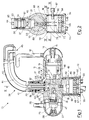
- FIG. 1 shows a tap provided in accordance with the present invention and indicated generally by reference number 10.
- Said tap comprises a body 11 which can be fastened below opposite a hole in a surface 12, e.g. the edge of a sink.
- the body 11 comprises a seat 46 for reception of a single-control mixing cartridge 13 of the known art, e.g. the ceramic disc type well known to those skilled in the art.
- the cartridge has a control pin 14 connected through a cover element 15 to an operating lever 16.
- the cartridge 13 has inlets 17 and 18 connectable as clarified below to hot and cold sanitary water sources.
- the cartridge 13 also has an outlet 19 debouching into a chamber 20 connected through a duct 21 to a first zone or chamber 22 of a seat 92 for rotating engagement of an end or engagement element 23 of a delivery tube element 24.
- the body 11 In a position opposite that of the cartridge 13 the body 11 has a seat 47 for a known stem valve 25 commanded to rotate by a lever 26 projecting radially from a cover element 27 keyed onto the stem control pin 28.
- the stem valve 25 has an inlet 29 and an outlet 30 debouching into a chamber 31 connected through a duct 32 to a second zone or chamber 33 of the engagement seat of the tube element 24.
- the cylindrical end 23 of the tube element has a peripheral groove 34 in which is inserted a screw or pin 35 to allow its rotation around the vertical axis preventing simultaneously its withdrawal from the seat.
- the end element 23 also has peripheral seats for O-rings 36, 37 for hydraulic seal toward the exterior and a discoid terminal zone 38 with hydraulic seal O-ring 39 separating the zones 22, 33.
- the tube element 24 comprises a first external tube 40 connected through a passage 41 of the engagement element 23 and through holes 42 to the first zone 22 identified by a radial restriction of the engagement element 23.
- a second tube 44 concentric with the first passes axially through the engagement element to debouch into the second zone 33. In this manner the external tube 40 leads to a delivery mouth 45 the water delivered by the mixer 13 while the tube 44 leads to the mouth 45 the water delivered by the stem 25.
- a selector element 49 In the base or foot of the body 11 there is another seat 48 for reception of a selector element 49.
- the seat 48 is closed below by a closing element or plug 50 in which are present (as seen also in FIG. 3) passing engagement (e.g. screwed) seats 51, 52, 53, 54 for ducts 55 for connection of the tap to the water sources.
- the selector 49 and the plug 50 are held in position by a screw 56 which traverses them axially for screwing into the body 11 of the tap 10.
- the selector 49 comprises a cup body or casing 57 with generally cylindrical side wall, a bottom 58 at a lower end and an opposite open upper end.
- the bottom comprises four openings positioned to coincide with the passing seats of the plug 50.
- a first or lower fixed disc 59 with four passages 60, 61, 62, 63 (FIG. 3) arranged to coincide with the corresponding passages in the bottom 58.
- a second disc or intermediate rotating selection disc 64 is stacked on the first and over it is stacked a third or top fixed disc 65 having four passages 66, 67, 68, 69 (FIG. 4) aligned with the corresponding four passages in the lower disc 59.
- the lower and upper discs are held in their position with passages aligned by tabs 70, 71 engaged in side grooves 72 on the peripheral wall of the body 57.
- the intermediate disc rotates axially and freely.
- the casing 57 is closed at its upper end by a cover 73 having side tabs 74 for engagement in the grooves 72 for its angular positioning and tabs 75 for snap engagement in seats 76 of the casing.
- Assembly of the selector elements is done by inserting in the casing the three stacked disks and placing over them the cover 73 in such a manner that it engages its snap tabs 75 in the seats 76 of the casing.
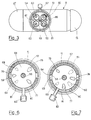
- the passages in the lower and upper discs are arranged on two diameters of the discs substantially at right angles to each other.
- the intermediate disc has only three passages arranged in such a manner that two of them 77 and 78 overlie the passages 60, 61 and 66, 67 of the two fixed discs while the third passage 79 is arranged in an intermediate position between the passages 62, 63 and 68, 69.
- the casing 57 has a slit 80 extending peripherally to the height of the intermediate disc.
- the selector 49 is inserted in its seat 48 the slit 80 faces a complementary slit 81 in the body of the tap 11 for the passage of a handling pin 82 with its end inserted in a seat 83 in the intermediate disc.
- the intermediate disc can rotate radially between two end positions by manual action on the pin 82 as may be seen in broken lines in FIG. 4.
- the cover 73 has two pins 84, 85 (FIG. 4) projecting above to engage complementary seats in the housing 48 of the selector so as to ensure correct angular positioning.
- Analogous pins 86, 87 project from the base of the selector to engage complementary seats in the plug 50 so as to ensure alignment between the passages in the plug and those on the bottom of the selector.
- the tap 10 is connected by the unions 51, 52 to two sanitary water sources, hot and cold respectively, while the unions 53, 54 are connected one to a first treated water source, e.g. purified and gasified, and the other to a second treated water source, e.g. purified and cooled.
- a first treated water source e.g. purified and gasified
- a second treated water source e.g. purified and cooled.
- the passages 77, 78 of the moving disc and the corresponding passages in the fixed discs misalign to interrupt passage of the sanitary water to the mixing cartridge while the passage 79 aligns with one of the two treated water passages to the stem 25.
- FIG. 7 shows alignment with the passages of the water arriving from the union 53
- specular operation would bring the passage 79 into alignment with the passages of the water arriving from the union 54.
- the stem valve 25 regulates flow of the treated water selected by the position of the lever 82 and water issues from the mouth 45 through the duct 44.
- the passages in the fixed discs have advantageously an outlet mouth on the surface of the disc opposite the intermediate disc of circular form so as to mate with the passages toward the unions and toward the ducts in the body 11 while the mouth on the side facing the intermediate disc has elongated form with one part of greater width toward the periphery of the disc analogously to the form of the passages on the moving disc.
- Said elongated form was found advantageous for providing easy selection as is readily imaginable for those skilled in the art.
- the passages of the former have a surface area smaller than that of the latter just as the duct 44 has a smaller cross section than the duct 40.
- the form of the device shown can be changed to suit it to specific aesthetic or construction requirements.
- the two delivery tubes are shown concentric, it is readily imaginable to those skilled in the art how to obtain an embodiment with side-by-side tubes or a single tube divided by a longitudinal internal diaphragm. Naturally if complete separation of the paths for the water coming from the two sets of sources connected to the two tap controls is not required, even a single tube can be used.
- FIG. 8 shows a possible variant of the tube delivery part of the above described tap. Similar parts are indicated by the same reference numbers as in FIG. 1 with 100 added.
- axial rotation with blocking against withdrawal is provided by a screw or pin 135 insert in a peripheral groove 134 of the engagement element 123.
- a tubular jacket 198 which forms the exterior of the tube delivery element and terminates at the other end with a delivery mouth 145.
- the engagement element 123 has a first internal passage 141 terminating with a hole 142 for connection of the first tube 140 with the zone 22 in which debouches the passage 21 coming from the mixer.
- the engagement element also has a second internal passage 197 for connection of the second tube 144 with the zone 33 in which debouches the passage 32 coming from the stem.
- the interior tubes 140 and 144 are separated from the interior wall of the jacket 198 so as to be thermally insulated from the exterior. Although a mere layer of air proved to be sufficient, the insulation can be increased if desired by placing between the tubes and the jacket a layer of low conductivity thermal material.
- control pin 82 is shown to be inserted directly in the intermediate disc, it is possible to imagine, especially for discs made of ceramic material, the use of a ring nut surrounding peripherally the disc and to which is fastened the pin. It is also imaginable to those skilled in the art how the connections between the selector element, unions and ducts in the body of the device can ensure hydraulic seal and require gaskets, e.g. O-rings, not shown for the sake of simplicity in the drawings.
- gaskets e.g. O-rings
Landscapes
- Engineering & Computer Science (AREA)
- General Engineering & Computer Science (AREA)
- Mechanical Engineering (AREA)
- Health & Medical Sciences (AREA)
- Life Sciences & Earth Sciences (AREA)
- Hydrology & Water Resources (AREA)
- Public Health (AREA)
- Water Supply & Treatment (AREA)
- Multiple-Way Valves (AREA)
- Axle Suspensions And Sidecars For Cycles (AREA)
- Picture Signal Circuits (AREA)
Applications Claiming Priority (3)
| Application Number | Priority Date | Filing Date | Title |
|---|---|---|---|
| ITMI920560 | 1992-03-11 | ||
| ITMI920560U | 1992-06-02 | ||
| ITMI920560U IT226651Z2 (it) | 1992-06-02 | 1992-06-02 | Rubinetto a doppio comando con selettore |
Publications (2)
| Publication Number | Publication Date |
|---|---|
| EP0577164A1 true EP0577164A1 (fr) | 1994-01-05 |
| EP0577164B1 EP0577164B1 (fr) | 1996-10-02 |
Family
ID=11362374
Family Applications (1)
| Application Number | Title | Priority Date | Filing Date |
|---|---|---|---|
| EP93201248A Expired - Lifetime EP0577164B1 (fr) | 1992-06-02 | 1993-05-01 | Soupape de double manoeuvre avec sélecteur |
Country Status (7)
| Country | Link |
|---|---|
| US (1) | US5293901A (fr) |
| EP (1) | EP0577164B1 (fr) |
| AT (1) | ATE143709T1 (fr) |
| DE (1) | DE69305113T2 (fr) |
| ES (1) | ES2092747T3 (fr) |
| IL (1) | IL105625A (fr) |
| IT (1) | IT226651Z2 (fr) |
Cited By (19)
| Publication number | Priority date | Publication date | Assignee | Title |
|---|---|---|---|---|
| EP0701028A1 (fr) * | 1994-09-12 | 1996-03-13 | Kwc Ag | Armature sanitaire |
| US5634220A (en) * | 1994-07-15 | 1997-06-03 | Chiu; Hung-Li | Double-functional faucet structure |
| WO1999009264A1 (fr) * | 1997-08-20 | 1999-02-25 | Margret Spiegel | Melangeur et procede permettant de distribuer de l'eau froide contenant du co¿2? |
| EP1101874A1 (fr) * | 1999-11-18 | 2001-05-23 | Roberto Crolla S.N.C. | Robinet de distribution d'eau |
| US6289531B1 (en) * | 1998-12-08 | 2001-09-18 | Friedrich Grohe Ag & Co. Kg | Faucet valve fixture |
| DE19756012C2 (de) * | 1996-12-20 | 2003-04-10 | Masco Corp Of Indiana Indianap | Wasserhahn-Handgriffbaugruppe |
| WO2007113663A2 (fr) * | 2006-04-05 | 2007-10-11 | Electrolux Home Products Corporation N.V. | Ensemble robinet d'évier |
| WO2011076293A1 (fr) * | 2009-12-24 | 2011-06-30 | Naegeler Juergen | Robinet d'eau à deux canaux d'amenée |
| ITMI20102471A1 (it) * | 2010-12-30 | 2012-07-01 | Gm Rubinetterie S R L | Sistema e gruppo valvolare per la miscelazione-erogazione di acqua sanitaria e di acqua depurata |
| EP2685012A1 (fr) * | 2012-07-13 | 2014-01-15 | Hansgrohe SE | Robinet comprenant un bec rotateur |
| ITMI20132072A1 (it) * | 2013-12-12 | 2015-06-13 | Gm Rubinetterie S R L | Dispositivo di erogazione con canna abbattibile |
| EP2975185A1 (fr) * | 2014-07-14 | 2016-01-20 | BLANCO GmbH + Co KG | Robinet avec pomme de douche extractible et sortie supplementaire pour eau bouillante |
| GB2531141A (en) * | 2014-08-28 | 2016-04-13 | Greg Rowe Ltd | Water tap body and installation |
| EP3062002A1 (fr) * | 2015-02-25 | 2016-08-31 | Flühs Drehtechnik GmbH | Partie supérieure de soupape |
| EP3062001A1 (fr) * | 2015-02-25 | 2016-08-31 | Flühs Drehtechnik GmbH | Partie supérieure de soupape |
| EP2937477A4 (fr) * | 2012-12-20 | 2016-10-05 | Franke Technology & Trademark | Appareil d'évacuation de liquide |
| EP3269883A1 (fr) * | 2016-07-15 | 2018-01-17 | GM Rubinetterie S.r.l. | Robinet avec dispositif de traitement d'eau pour le montage mural |
| EP3382110A1 (fr) | 2017-03-31 | 2018-10-03 | Brita GmbH | Robinet et système permettant de fournir sélectivement un liquide traité et non traité |
| EP3766828A3 (fr) * | 2019-07-15 | 2021-02-17 | BLANCO GmbH + Co KG | Armature sanitaire destinée à la distribution des liquides traités |
Families Citing this family (18)
| Publication number | Priority date | Publication date | Assignee | Title |
|---|---|---|---|---|
| IL140697A (en) * | 1998-02-18 | 2004-06-01 | Yoav Granot | Water tap structure |
| CN1262776C (zh) * | 1998-11-16 | 2006-07-05 | 约夫·格兰诺特 | 水龙头结构 |
| US20070235091A1 (en) * | 2006-04-06 | 2007-10-11 | Yoav Granot | Water tap assembly having a pull-out water-discharge head |
| US20090014379A1 (en) * | 2007-07-13 | 2009-01-15 | Kwan David C | Filtration faucet system |
| WO2009076981A1 (fr) | 2007-12-15 | 2009-06-25 | Grohe Ag | Robinet d'eau chaude à tuyau de sortie isolé |
| AU2010201879A1 (en) * | 2009-05-12 | 2010-12-02 | Li Jun Xia | A tap arrangement |
| AU2010219366A1 (en) * | 2009-09-17 | 2011-03-31 | Li Jun Xia | A multi tap arrangement |
| US11091901B2 (en) | 2011-07-13 | 2021-08-17 | Delta Faucet Company | Faucet handle with angled interface |
| US8820705B2 (en) | 2011-07-13 | 2014-09-02 | Masco Corporation Of Indiana | Faucet handle with angled interface |
| WO2015002950A1 (fr) | 2013-07-01 | 2015-01-08 | As Ip Holdco, Llc | Systèmes et procédés de préparation de boisson dosée en une tasse |
| CN204328076U (zh) * | 2014-11-25 | 2015-05-13 | 厦门建霖工业有限公司 | 净水阀芯结构 |
| CN204704428U (zh) * | 2015-04-18 | 2015-10-14 | 厦门建霖工业有限公司 | 一种双出水龙头 |
| DE102015005098A1 (de) * | 2015-04-22 | 2016-10-27 | Grohe Ag | Sanitärarmatur für zumindest zwei Fluide |
| US20180258621A1 (en) * | 2015-05-20 | 2018-09-13 | Binay Kumar Binay Kumar | Fluid mixer tap or valve |
| US9739039B2 (en) * | 2015-11-26 | 2017-08-22 | Hain Yo Enterprises Co. Ltd. | Faucet for switching between multiple water sources |
| US9644353B1 (en) * | 2015-12-21 | 2017-05-09 | Hain Yo Enterprises Co. Ltd. | Faucet with pipe-in-pipe structure |
| CN105508659B (zh) * | 2016-01-27 | 2018-01-26 | 厦门建霖工业有限公司 | 机械式单把净水龙头及其定量出水方法 |
| US11193257B2 (en) * | 2019-11-04 | 2021-12-07 | Kuching International Ltd. | Outlet structure of faucet valve seat |
Citations (6)
| Publication number | Priority date | Publication date | Assignee | Title |
|---|---|---|---|---|
| GB683694A (en) * | 1949-07-30 | 1952-12-03 | Meynell & Sons Ltd | Improvements in, or relating to, valves |
| GB2033543A (en) * | 1978-08-15 | 1980-05-21 | Manicom A W | A valve means for anaesthetic apparatus |
| DE2945834A1 (de) * | 1978-11-13 | 1980-11-20 | Baukow Rtb Gmbh & Co Kg | Ventil fuer fluide, insbesondere in einem spueler, einer mischbatterie oder einem hahn o.dgl. armaturen fuer installationszwecke |
| GB2234327A (en) * | 1989-04-14 | 1991-01-30 | S & C Thermofluids Ltd | Valve |
| WO1991007614A1 (fr) * | 1989-11-21 | 1991-05-30 | Robert Bryan Perrin | Robinet d'eau |
| DE4031764A1 (de) * | 1990-08-07 | 1992-02-13 | Scheffer Kludi Armaturen | Einloch-mischbatterie fuer spueltische |
Family Cites Families (4)
| Publication number | Priority date | Publication date | Assignee | Title |
|---|---|---|---|---|
| JPS61175377A (ja) * | 1985-01-29 | 1986-08-07 | Toto Ltd | 湯水混合栓 |
| US4794952A (en) * | 1987-02-04 | 1989-01-03 | American Standard | Combination mixing valve and appliance valve assembly |
| DE4035838A1 (de) * | 1990-11-10 | 1992-07-23 | Grohe Armaturen Friedrich | Wasserventil fuer sanitaere anlagen |
| DE69110630T2 (de) * | 1990-12-05 | 1995-12-14 | Telma Guzzini S R L | Ausgabevorrichtungen mit Mehrwegehahn. |
-
1992
- 1992-06-02 IT ITMI920560U patent/IT226651Z2/it active IP Right Grant
-
1993
- 1993-05-01 ES ES93201248T patent/ES2092747T3/es not_active Expired - Lifetime
- 1993-05-01 EP EP93201248A patent/EP0577164B1/fr not_active Expired - Lifetime
- 1993-05-01 AT AT93201248T patent/ATE143709T1/de not_active IP Right Cessation
- 1993-05-01 DE DE69305113T patent/DE69305113T2/de not_active Expired - Fee Related
- 1993-05-05 US US08/056,893 patent/US5293901A/en not_active Expired - Lifetime
- 1993-05-06 IL IL10562593A patent/IL105625A/en not_active IP Right Cessation
Patent Citations (6)
| Publication number | Priority date | Publication date | Assignee | Title |
|---|---|---|---|---|
| GB683694A (en) * | 1949-07-30 | 1952-12-03 | Meynell & Sons Ltd | Improvements in, or relating to, valves |
| GB2033543A (en) * | 1978-08-15 | 1980-05-21 | Manicom A W | A valve means for anaesthetic apparatus |
| DE2945834A1 (de) * | 1978-11-13 | 1980-11-20 | Baukow Rtb Gmbh & Co Kg | Ventil fuer fluide, insbesondere in einem spueler, einer mischbatterie oder einem hahn o.dgl. armaturen fuer installationszwecke |
| GB2234327A (en) * | 1989-04-14 | 1991-01-30 | S & C Thermofluids Ltd | Valve |
| WO1991007614A1 (fr) * | 1989-11-21 | 1991-05-30 | Robert Bryan Perrin | Robinet d'eau |
| DE4031764A1 (de) * | 1990-08-07 | 1992-02-13 | Scheffer Kludi Armaturen | Einloch-mischbatterie fuer spueltische |
Cited By (33)
| Publication number | Priority date | Publication date | Assignee | Title |
|---|---|---|---|---|
| US5634220A (en) * | 1994-07-15 | 1997-06-03 | Chiu; Hung-Li | Double-functional faucet structure |
| EP0701028A1 (fr) * | 1994-09-12 | 1996-03-13 | Kwc Ag | Armature sanitaire |
| DE19756012C2 (de) * | 1996-12-20 | 2003-04-10 | Masco Corp Of Indiana Indianap | Wasserhahn-Handgriffbaugruppe |
| WO1999009264A1 (fr) * | 1997-08-20 | 1999-02-25 | Margret Spiegel | Melangeur et procede permettant de distribuer de l'eau froide contenant du co¿2? |
| US6289531B1 (en) * | 1998-12-08 | 2001-09-18 | Friedrich Grohe Ag & Co. Kg | Faucet valve fixture |
| EP1101874A1 (fr) * | 1999-11-18 | 2001-05-23 | Roberto Crolla S.N.C. | Robinet de distribution d'eau |
| WO2007113663A2 (fr) * | 2006-04-05 | 2007-10-11 | Electrolux Home Products Corporation N.V. | Ensemble robinet d'évier |
| WO2007113663A3 (fr) * | 2006-04-05 | 2008-01-31 | Electrolux Home Prod Corp | Ensemble robinet d'évier |
| WO2011076293A1 (fr) * | 2009-12-24 | 2011-06-30 | Naegeler Juergen | Robinet d'eau à deux canaux d'amenée |
| ITMI20102471A1 (it) * | 2010-12-30 | 2012-07-01 | Gm Rubinetterie S R L | Sistema e gruppo valvolare per la miscelazione-erogazione di acqua sanitaria e di acqua depurata |
| EP2472150A1 (fr) * | 2010-12-30 | 2012-07-04 | GM Rubinetterie S.r.l. | Système et unité de soupape |
| US8671979B2 (en) | 2010-12-30 | 2014-03-18 | Gm Rubinetterie S.R.L. | System and valve unit for mixing-delivery sanitary water and/or purified water |
| EP2685012A1 (fr) * | 2012-07-13 | 2014-01-15 | Hansgrohe SE | Robinet comprenant un bec rotateur |
| CN103542217A (zh) * | 2012-07-13 | 2014-01-29 | 汉斯格罗欧洲公司 | 用于软管的出流嵌件 |
| CN103542217B (zh) * | 2012-07-13 | 2017-05-03 | 汉斯格罗欧洲公司 | 卫生设备配件 |
| EP2937477A4 (fr) * | 2012-12-20 | 2016-10-05 | Franke Technology & Trademark | Appareil d'évacuation de liquide |
| ITMI20132072A1 (it) * | 2013-12-12 | 2015-06-13 | Gm Rubinetterie S R L | Dispositivo di erogazione con canna abbattibile |
| EP2884012A1 (fr) | 2013-12-12 | 2015-06-17 | GM Rubinetterie S.r.l. | Dispositif d'alimentation avec canon oscillant |
| EP2975185A1 (fr) * | 2014-07-14 | 2016-01-20 | BLANCO GmbH + Co KG | Robinet avec pomme de douche extractible et sortie supplementaire pour eau bouillante |
| US10718439B2 (en) | 2014-08-28 | 2020-07-21 | Greg Rowe Limited | Water tap body and installation |
| GB2531141A (en) * | 2014-08-28 | 2016-04-13 | Greg Rowe Ltd | Water tap body and installation |
| GB2531141B (en) * | 2014-08-28 | 2018-12-05 | Greg Rowe Ltd | Water tap body and installation |
| US9958075B2 (en) | 2014-08-28 | 2018-05-01 | Greg Rowe Limited | Water tap body and installation |
| EP3062001A1 (fr) * | 2015-02-25 | 2016-08-31 | Flühs Drehtechnik GmbH | Partie supérieure de soupape |
| EP3062002A1 (fr) * | 2015-02-25 | 2016-08-31 | Flühs Drehtechnik GmbH | Partie supérieure de soupape |
| WO2016135153A1 (fr) * | 2015-02-25 | 2016-09-01 | Flühs Drehtechnik GmbH | Partie supérieure de soupape |
| TWI668385B (zh) * | 2015-02-25 | 2019-08-11 | 德商浮利士車工工程技術有限公司 | Upper valve |
| EP3269883A1 (fr) * | 2016-07-15 | 2018-01-17 | GM Rubinetterie S.r.l. | Robinet avec dispositif de traitement d'eau pour le montage mural |
| EP3757302A2 (fr) | 2017-03-31 | 2020-12-30 | Brita GmbH | Robinet et système permettant de fournir sélectivement un liquide traité et non traité |
| EP3382110A1 (fr) | 2017-03-31 | 2018-10-03 | Brita GmbH | Robinet et système permettant de fournir sélectivement un liquide traité et non traité |
| EP3766828A3 (fr) * | 2019-07-15 | 2021-02-17 | BLANCO GmbH + Co KG | Armature sanitaire destinée à la distribution des liquides traités |
| US11584630B2 (en) | 2019-07-15 | 2023-02-21 | Blanco Gmbh + Co Kg | Sanitary fitting for dispensing prepared liquids |
| US11702329B2 (en) | 2019-07-15 | 2023-07-18 | Blanco Gmbh + Co Kg | Sanitary fitting for dispensing prepared liquids |
Also Published As
| Publication number | Publication date |
|---|---|
| DE69305113T2 (de) | 1997-02-13 |
| IL105625A (en) | 1995-12-31 |
| DE69305113D1 (de) | 1996-11-07 |
| ES2092747T3 (es) | 1996-12-01 |
| IT226651Z2 (it) | 1997-07-01 |
| US5293901A (en) | 1994-03-15 |
| ITMI920560V0 (it) | 1992-06-02 |
| EP0577164B1 (fr) | 1996-10-02 |
| ATE143709T1 (de) | 1996-10-15 |
| ITMI920560U1 (it) | 1993-12-02 |
Similar Documents
| Publication | Publication Date | Title |
|---|---|---|
| EP0577164B1 (fr) | Soupape de double manoeuvre avec sélecteur | |
| US4378029A (en) | Single control faucet | |
| RU2091653C1 (ru) | Смесительный клапан | |
| US5095934A (en) | Fluid valve | |
| US7143786B2 (en) | Two-handle flow-through valve | |
| CN101688618B (zh) | 调节装置 | |
| KR20010088426A (ko) | 유동 전환기 조립체 | |
| US4972877A (en) | Bypass valve | |
| US6199586B1 (en) | Single-control mixing valve | |
| CN104321491A (zh) | 龙头以及具有煮沸水装置和该龙头的组件 | |
| KR20020013357A (ko) | 외부 정수기가 부착된 혼합수도꼭지 | |
| KR920008604B1 (ko) | 혼합 밸브 조립체 | |
| EP0593489B1 (fr) | Robinet mitigeur comprenant un boisseau spherique | |
| US7080790B2 (en) | Cartridge for sanitary appliances | |
| JP3085699B2 (ja) | 多機能複合水栓 | |
| US20030101510A1 (en) | Hot and cold water mixer tap with thermostatic unit and flow diverter unit | |
| US20060231146A1 (en) | Bypass valve | |
| IE850368L (en) | Single control hot and cold water supply valve | |
| CA3094865A1 (fr) | Robinets melangeurs, modules de robinets et ensembles de modules de robinets | |
| EP0092545B1 (fr) | Robinet a commande unique | |
| US4832083A (en) | Valve apparatus | |
| CN215806505U (zh) | 一种导流阀以及含导流阀的水龙头阀体 | |
| EP0080018B1 (fr) | Robinet mitigeur | |
| CN215410364U (zh) | 一种结构改进的三功能淋浴龙头 | |
| CN109237077B (zh) | 一种双水路水龙头阀芯 |
Legal Events
| Date | Code | Title | Description |
|---|---|---|---|
| PUAI | Public reference made under article 153(3) epc to a published international application that has entered the european phase |
Free format text: ORIGINAL CODE: 0009012 |
|
| AK | Designated contracting states |
Kind code of ref document: A1 Designated state(s): AT BE CH DE DK ES FR GB GR IT LI LU NL SE |
|
| 17P | Request for examination filed |
Effective date: 19940222 |
|
| 17Q | First examination report despatched |
Effective date: 19951206 |
|
| GRAH | Despatch of communication of intention to grant a patent |
Free format text: ORIGINAL CODE: EPIDOS IGRA |
|
| GRAH | Despatch of communication of intention to grant a patent |
Free format text: ORIGINAL CODE: EPIDOS IGRA |
|
| GRAA | (expected) grant |
Free format text: ORIGINAL CODE: 0009210 |
|
| ITF | It: translation for a ep patent filed |
Owner name: GUZZI E RAVIZZA S.R.L. |
|
| AK | Designated contracting states |
Kind code of ref document: B1 Designated state(s): AT BE CH DE DK ES FR GB GR IT LI LU NL SE |
|
| PG25 | Lapsed in a contracting state [announced via postgrant information from national office to epo] |
Ref country code: NL Free format text: LAPSE BECAUSE OF FAILURE TO SUBMIT A TRANSLATION OF THE DESCRIPTION OR TO PAY THE FEE WITHIN THE PRESCRIBED TIME-LIMIT Effective date: 19961002 Ref country code: LI Effective date: 19961002 Ref country code: GR Free format text: LAPSE BECAUSE OF FAILURE TO SUBMIT A TRANSLATION OF THE DESCRIPTION OR TO PAY THE FEE WITHIN THE PRESCRIBED TIME-LIMIT Effective date: 19961002 Ref country code: DK Effective date: 19961002 Ref country code: CH Effective date: 19961002 Ref country code: BE Effective date: 19961002 Ref country code: AT Effective date: 19961002 |
|
| REF | Corresponds to: |
Ref document number: 143709 Country of ref document: AT Date of ref document: 19961015 Kind code of ref document: T |
|
| REF | Corresponds to: |
Ref document number: 69305113 Country of ref document: DE Date of ref document: 19961107 |
|
| REG | Reference to a national code |
Ref country code: ES Ref legal event code: FG2A Ref document number: 2092747 Country of ref document: ES Kind code of ref document: T3 |
|
| PG25 | Lapsed in a contracting state [announced via postgrant information from national office to epo] |
Ref country code: SE Effective date: 19970102 |
|
| ET | Fr: translation filed | ||
| NLV1 | Nl: lapsed or annulled due to failure to fulfill the requirements of art. 29p and 29m of the patents act | ||
| REG | Reference to a national code |
Ref country code: CH Ref legal event code: PL |
|
| PG25 | Lapsed in a contracting state [announced via postgrant information from national office to epo] |
Ref country code: LU Free format text: LAPSE BECAUSE OF NON-PAYMENT OF DUE FEES Effective date: 19970531 |
|
| PLBE | No opposition filed within time limit |
Free format text: ORIGINAL CODE: 0009261 |
|
| STAA | Information on the status of an ep patent application or granted ep patent |
Free format text: STATUS: NO OPPOSITION FILED WITHIN TIME LIMIT |
|
| 26N | No opposition filed | ||
| REG | Reference to a national code |
Ref country code: GB Ref legal event code: IF02 |
|
| PGFP | Annual fee paid to national office [announced via postgrant information from national office to epo] |
Ref country code: GB Payment date: 20070322 Year of fee payment: 15 Ref country code: ES Payment date: 20070322 Year of fee payment: 15 |
|
| PGFP | Annual fee paid to national office [announced via postgrant information from national office to epo] |
Ref country code: DE Payment date: 20070726 Year of fee payment: 15 |
|
| PGFP | Annual fee paid to national office [announced via postgrant information from national office to epo] |
Ref country code: IT Payment date: 20070530 Year of fee payment: 15 |
|
| PGFP | Annual fee paid to national office [announced via postgrant information from national office to epo] |
Ref country code: FR Payment date: 20070328 Year of fee payment: 15 |
|
| GBPC | Gb: european patent ceased through non-payment of renewal fee |
Effective date: 20080501 |
|
| REG | Reference to a national code |
Ref country code: FR Ref legal event code: ST Effective date: 20090119 |
|
| PG25 | Lapsed in a contracting state [announced via postgrant information from national office to epo] |
Ref country code: FR Free format text: LAPSE BECAUSE OF NON-PAYMENT OF DUE FEES Effective date: 20080602 Ref country code: DE Free format text: LAPSE BECAUSE OF NON-PAYMENT OF DUE FEES Effective date: 20081202 |
|
| PG25 | Lapsed in a contracting state [announced via postgrant information from national office to epo] |
Ref country code: GB Free format text: LAPSE BECAUSE OF NON-PAYMENT OF DUE FEES Effective date: 20080501 |
|
| REG | Reference to a national code |
Ref country code: ES Ref legal event code: FD2A Effective date: 20080503 |
|
| PG25 | Lapsed in a contracting state [announced via postgrant information from national office to epo] |
Ref country code: IT Free format text: LAPSE BECAUSE OF NON-PAYMENT OF DUE FEES Effective date: 20080501 |
|
| PG25 | Lapsed in a contracting state [announced via postgrant information from national office to epo] |
Ref country code: ES Free format text: LAPSE BECAUSE OF NON-PAYMENT OF DUE FEES Effective date: 20080503 |