EP0573232B1 - Spritzgiessverfahren, Spritzgiessform und spritzgegossener Gegenstand - Google Patents
Spritzgiessverfahren, Spritzgiessform und spritzgegossener Gegenstand Download PDFInfo
- Publication number
- EP0573232B1 EP0573232B1 EP93304187A EP93304187A EP0573232B1 EP 0573232 B1 EP0573232 B1 EP 0573232B1 EP 93304187 A EP93304187 A EP 93304187A EP 93304187 A EP93304187 A EP 93304187A EP 0573232 B1 EP0573232 B1 EP 0573232B1
- Authority
- EP
- European Patent Office
- Prior art keywords
- resin
- weld
- cavity
- reservoir
- mold
- Prior art date
- Legal status (The legal status is an assumption and is not a legal conclusion. Google has not performed a legal analysis and makes no representation as to the accuracy of the status listed.)
- Expired - Lifetime
Links
- 238000001746 injection moulding Methods 0.000 title claims description 23
- 229920005989 resin Polymers 0.000 claims description 151
- 239000011347 resin Substances 0.000 claims description 151
- 238000000465 moulding Methods 0.000 claims description 32
- 229920005992 thermoplastic resin Polymers 0.000 claims description 10
- 230000005012 migration Effects 0.000 claims description 4
- 238000013508 migration Methods 0.000 claims description 4
- 229920000106 Liquid crystal polymer Polymers 0.000 claims description 3
- 239000011256 inorganic filler Substances 0.000 claims description 3
- 229910003475 inorganic filler Inorganic materials 0.000 claims description 3
- 238000000034 method Methods 0.000 description 19
- 230000008569 process Effects 0.000 description 16
- 230000015572 biosynthetic process Effects 0.000 description 6
- 239000000945 filler Substances 0.000 description 6
- 230000000052 comparative effect Effects 0.000 description 3
- 230000000694 effects Effects 0.000 description 3
- 239000003365 glass fiber Substances 0.000 description 3
- 230000006872 improvement Effects 0.000 description 3
- 230000008901 benefit Effects 0.000 description 2
- 230000008859 change Effects 0.000 description 2
- 229920006038 crystalline resin Polymers 0.000 description 2
- 239000012765 fibrous filler Substances 0.000 description 2
- 238000002347 injection Methods 0.000 description 2
- 239000007924 injection Substances 0.000 description 2
- 239000004977 Liquid-crystal polymers (LCPs) Substances 0.000 description 1
- 239000004734 Polyphenylene sulfide Substances 0.000 description 1
- 230000010485 coping Effects 0.000 description 1
- 230000003247 decreasing effect Effects 0.000 description 1
- 238000001514 detection method Methods 0.000 description 1
- 230000009969 flowable effect Effects 0.000 description 1
- 229920000069 polyphenylene sulfide Polymers 0.000 description 1
- 238000003825 pressing Methods 0.000 description 1
- 238000007711 solidification Methods 0.000 description 1
- 230000008023 solidification Effects 0.000 description 1
Images


Classifications
-
- B—PERFORMING OPERATIONS; TRANSPORTING
- B29—WORKING OF PLASTICS; WORKING OF SUBSTANCES IN A PLASTIC STATE IN GENERAL
- B29C—SHAPING OR JOINING OF PLASTICS; SHAPING OF MATERIAL IN A PLASTIC STATE, NOT OTHERWISE PROVIDED FOR; AFTER-TREATMENT OF THE SHAPED PRODUCTS, e.g. REPAIRING
- B29C45/00—Injection moulding, i.e. forcing the required volume of moulding material through a nozzle into a closed mould; Apparatus therefor
- B29C45/0025—Preventing defects on the moulded article, e.g. weld lines, shrinkage marks
-
- B—PERFORMING OPERATIONS; TRANSPORTING
- B29—WORKING OF PLASTICS; WORKING OF SUBSTANCES IN A PLASTIC STATE IN GENERAL
- B29C—SHAPING OR JOINING OF PLASTICS; SHAPING OF MATERIAL IN A PLASTIC STATE, NOT OTHERWISE PROVIDED FOR; AFTER-TREATMENT OF THE SHAPED PRODUCTS, e.g. REPAIRING
- B29C45/00—Injection moulding, i.e. forcing the required volume of moulding material through a nozzle into a closed mould; Apparatus therefor
- B29C45/0005—Injection moulding, i.e. forcing the required volume of moulding material through a nozzle into a closed mould; Apparatus therefor using fibre reinforcements
-
- B—PERFORMING OPERATIONS; TRANSPORTING
- B29—WORKING OF PLASTICS; WORKING OF SUBSTANCES IN A PLASTIC STATE IN GENERAL
- B29C—SHAPING OR JOINING OF PLASTICS; SHAPING OF MATERIAL IN A PLASTIC STATE, NOT OTHERWISE PROVIDED FOR; AFTER-TREATMENT OF THE SHAPED PRODUCTS, e.g. REPAIRING
- B29C45/00—Injection moulding, i.e. forcing the required volume of moulding material through a nozzle into a closed mould; Apparatus therefor
- B29C45/0025—Preventing defects on the moulded article, e.g. weld lines, shrinkage marks
- B29C2045/0039—Preventing defects on the moulded article, e.g. weld lines, shrinkage marks intermixing the injected material front at the weld line, e.g. by applying vibrations to the melt front
-
- B—PERFORMING OPERATIONS; TRANSPORTING
- B29—WORKING OF PLASTICS; WORKING OF SUBSTANCES IN A PLASTIC STATE IN GENERAL
- B29C—SHAPING OR JOINING OF PLASTICS; SHAPING OF MATERIAL IN A PLASTIC STATE, NOT OTHERWISE PROVIDED FOR; AFTER-TREATMENT OF THE SHAPED PRODUCTS, e.g. REPAIRING
- B29C45/00—Injection moulding, i.e. forcing the required volume of moulding material through a nozzle into a closed mould; Apparatus therefor
- B29C45/0025—Preventing defects on the moulded article, e.g. weld lines, shrinkage marks
- B29C2045/0044—Preventing defects on the moulded article, e.g. weld lines, shrinkage marks expelling moulding material outside the mould cavity at the weld line location
-
- B—PERFORMING OPERATIONS; TRANSPORTING
- B29—WORKING OF PLASTICS; WORKING OF SUBSTANCES IN A PLASTIC STATE IN GENERAL
- B29C—SHAPING OR JOINING OF PLASTICS; SHAPING OF MATERIAL IN A PLASTIC STATE, NOT OTHERWISE PROVIDED FOR; AFTER-TREATMENT OF THE SHAPED PRODUCTS, e.g. REPAIRING
- B29C45/00—Injection moulding, i.e. forcing the required volume of moulding material through a nozzle into a closed mould; Apparatus therefor
- B29C45/0013—Injection moulding, i.e. forcing the required volume of moulding material through a nozzle into a closed mould; Apparatus therefor using fillers dispersed in the moulding material, e.g. metal particles
-
- B—PERFORMING OPERATIONS; TRANSPORTING
- B29—WORKING OF PLASTICS; WORKING OF SUBSTANCES IN A PLASTIC STATE IN GENERAL
- B29C—SHAPING OR JOINING OF PLASTICS; SHAPING OF MATERIAL IN A PLASTIC STATE, NOT OTHERWISE PROVIDED FOR; AFTER-TREATMENT OF THE SHAPED PRODUCTS, e.g. REPAIRING
- B29C45/00—Injection moulding, i.e. forcing the required volume of moulding material through a nozzle into a closed mould; Apparatus therefor
- B29C45/17—Component parts, details or accessories; Auxiliary operations
- B29C45/26—Moulds
- B29C45/2628—Moulds with mould parts forming holes in or through the moulded article, e.g. for bearing cages
-
- B—PERFORMING OPERATIONS; TRANSPORTING
- B29—WORKING OF PLASTICS; WORKING OF SUBSTANCES IN A PLASTIC STATE IN GENERAL
- B29C—SHAPING OR JOINING OF PLASTICS; SHAPING OF MATERIAL IN A PLASTIC STATE, NOT OTHERWISE PROVIDED FOR; AFTER-TREATMENT OF THE SHAPED PRODUCTS, e.g. REPAIRING
- B29C45/00—Injection moulding, i.e. forcing the required volume of moulding material through a nozzle into a closed mould; Apparatus therefor
- B29C45/17—Component parts, details or accessories; Auxiliary operations
- B29C45/46—Means for plasticising or homogenising the moulding material or forcing it into the mould
- B29C45/56—Means for plasticising or homogenising the moulding material or forcing it into the mould using mould parts movable during or after injection, e.g. injection-compression moulding
-
- B—PERFORMING OPERATIONS; TRANSPORTING
- B29—WORKING OF PLASTICS; WORKING OF SUBSTANCES IN A PLASTIC STATE IN GENERAL
- B29K—INDEXING SCHEME ASSOCIATED WITH SUBCLASSES B29B, B29C OR B29D, RELATING TO MOULDING MATERIALS OR TO MATERIALS FOR MOULDS, REINFORCEMENTS, FILLERS OR PREFORMED PARTS, e.g. INSERTS
- B29K2105/00—Condition, form or state of moulded material or of the material to be shaped
- B29K2105/0079—Liquid crystals
Definitions
- the present invention relates to an improved injection molding process. More particularly, the improvements reside in considerable increases in the strength of welds within and at the periphery of injection moldings of thermoplastic resins.
- the resin In injection molding, as the resin is injected into a mold cavity it may divide into streams which then reunite in the form of a weld.
- the dividing may be caused by a core or the like provided in the mold cavity or, if the article being molded has a non-uniform thicknesses, by differences in the resin flows rates between those in large thickness regions and those in small thickness regions.
- Such a weld is likely to occur as a result of one or both of the mentioned above and it is therefore often difficult to obtain a molded product of complicated configuration, as is required for many practicable articles, moldings but which is free from welds.
- welds not only degrade the appearance of a molding due to the occurrence of streaky pattern known as "weld mark", but also cause a serious problem in that the strength of a molding is much lower than that inherently possessed by the resin.
- the lower strength at the "weld” arises largely because the divided resin streams are merely united by fusing and unification but without any uniform mixing of the resin streams.
- EP-A-362,648 discloses an injection molding process for thermoplastic resin, which uses a mold having a mold cavity with an internal shape which divides the injected resin into streams which subsequently reunite and weld together within the cavity which uses a mold provided with a resin reservoir protruding therefrom adjacent a region at which the streams reunite.
- the resin reservoir has a retractable piston (9), for feeding molten resin into the mold to fill the cavity by advancing the piston to force resin from the reservoir into the cavity.
- the present inventor has found a process for effectively improving weld strength or the like by causing the migration of the resin at the welds while the resin maintains its flowability in the mold cavity after the formation of welds so as to disturb the orientation of the resin and filler at the welds.
- the invention provides an injection molding process for thermoplastic resin, which uses a mold having a mold cavity with an internal shape which divides the injected resin into streams which subsequently reunite and weld together within the cavity, characterized by using a mold provided with at least one resin reservoir protruding therefrom adjacent to a region at which the streams reunite, the said resin reservoir having a retractable piston, and feeding molten resin into the mold to fill the cavity and form the weld while the piston is in a retracted or advanced state, and either advancing the piston toward the passageway to force resin from the resin reservoir into the cavity or retracting the piston to withdraw resin from the passageway into the resin reservoir so as to reinforce the weld by migration of the resin in the weld and wherein the movement of the piston for forcing the resin from the resin reservoir into the cavity or for withdrawing the resin from the cavity into the resin reservoir is conducted while the piston is vibrated.
- Figure 1 is a view of a mold incorporating a resin reservoir for use in a process according to the present invention, wherein (a) is a schematic plan view and (b) is a schematic view of a section along line 1a-1a in (a).
- Figure 2 is a view of another mold incorporating a resin reservoir for use in a process according to the present invention, wherein (a) is a schematic plan view and (b) is a schematic view of a section along line 2a-2a in (a).
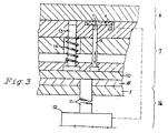
- Figure 3 is a schematic view of a section around the resin reservoir of a mold corresponding to one in Figure 1. It shows the operating parts of one form of a piston for forcing resin from the resin reservoir into the mold cavity or for withdrawing resin from the cavity into the resin reservoir.
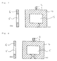
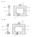
- Figures 4 to 10 are each a diagrammatic view of versions mold as shown in Figure 1, schematically showing the condition of injected resin in the case where the resin is forced from the resin reservoir into the mold cavity, again wherein (a) is a schematic plan view and (b) is a schematic view of a section corresponding to one along line 1a-1a in Figure 1.
- Figures 1 and 2 each show one mode of the mold (molding) according to the present invention which are improved over the conventional molds (moldings) in which welds are formed in respect of producing moldings having increased weld strength, the improvement comprising providing the mold with a resin reservoir (1) protruding from a mold cavity (4) in a preselected position, i.e., in at least one of divided resin passages ranging from the point where the injected molten resin is divided into two streams to a weld formed by the union of the resin streams.
- the resin reservoir (1) is provided with a retractable piston (9) - shown in Figure 3 but not in the other Figures - for either forcing the resin from the reservoir (1) into the cavity (4) or withdrawing the resin from the cavity (4) into the reservoir (1).
- the injected molten resin is divided into two streams A1 and A2 in front of a core (5), and a weld is formed at a point B (see Figures 1 and 2) where the resin streams are united.
- this weld has the drawback that the fronts of the two divided resin streams meeting at the weld point merely abut each other as if they were closely adhered to each other. Not only the resin but also any filler contained in the resin is oriented across the weld without undergoing uniform mixing, so that the strength of the weld is poor.
- the piston is advanced toward the cavity (4) to force the resin from the resin reservoir (1) into the cavity (4) so as to cause a pressure difference between two sides of the weld to force the resin on one side not provided with a resin reservoir into the resin on the other side provided with a resin reservoir.
- the molten resin is fed into the mold while the piston (9) is in an advanced state and is divided into streams, which are united to form a weld.
- the piston (9) is retracted to withdraw the resin from the cavity (4) into the resin reservoir (1) so as to cause a pressure difference between two sides of the weld to force the resin on one side not provided with a reservoir into the resin on the side which has a reservoir.
- the movement of the piston (9) for forcing the resin from the reservoir (1) into the cavity (4) or for withdrawing the resin from the cavity (4) into the resin reservoir is conducted while the piston (9) is vibrated. This vibration is preferably conducted at a cycle of 10 Hz or below.
- a system may be adopted in which a sensor S (see Figure 3) capable of detecting the condition of resin filling in the cavity (4) is provided in the mold or on a molding machine side and a hydraulic pressure device or the like is actuated in accordance with a detection signal from the sensor S regarding the condition of resin filling in the cavity to move the piston (9) for forcing the resin from the reservoir (1) into the cavity (4) or for withdrawing the resin from the cavity (4) into the reservoir (1).
- a sensor is not essential and instead a system may be adopted in which the time required to charge the old cavity with resin and to form a weld is previously measured and the movement of the piston (9) can be preselected and adjusted accordingly.
- Figure 3 shows one example of the mold structure suitable for use in a process according to the present invention.
- forcing of the resin from the resin reservoir (1) into the cavity (4) and withdrawal of the resin from the cavity (4) into the reservoir (1) are carried out by a pin-shaped piston (9).
- the advance of the piston (9) is performed by a local pressuring device (12) provided with vibration means.
- the retraction of the piston (9) is performed by a forced retraction spring (14).
- the pressuring device (12) is mounted on a movable platen (8), and is capable of vibrating and pressing a pressure plate (10) via a pressure rod (11).
- Retraction of the pressure plate (10) is performed by the spring (14) disposed in the mold so as for the pressure plate (10) to be forced toward the platen (8).
- Operational control of vibration timing, vibration frequency and vibration time is performed by the local pressuring device.
- this device it is feasible to control both a process in which the molten resin is injected while a resin reservoir is available by retracting a pin-shaped piston by means of a forced retraction spring so as to form a weld and then a vibrational force is applied by the local pressuring device through a pressure rod to a pressure plate and conveyed to a pin-shaped piston so that the piston is advanced to force the resin from the resin reservoir into the cavity, and a process in which the molten resin is injected into the mold while the pin-shaped piston is in an advanced state, through a pressure rod and a pressure plate, by the local pressuring device so as to form a weld and then the operation of the local pressuring device is discontinued, followed by retraction of the pin-shaped piston by means of a forced retraction spring, to thereby withdraw the resin from the cavity (4) into the resin reservoir.
- timing for forcing the resin from the resin reservoir into the cavity or for withdrawing the resin from the cavity into the resin reservoir it may be performed even several seconds after the formation of the weld, as long as the molten resin maintains its flowability to such an extent that the resin in the resin reservoir can be forced into the cavity or the resin in the cavity is flowable into the resin reservoir.
- it is preferably performed immediately after the formation of the weld, because the amount of the forced or withdrawn resin is large due to the high flowability of the resin, so that the improvement of the strength of the weld is promoted.
- Figs. 4 to 7 schematically show the change with time of the condition of injected resin in the case where the resin is forced from the reservoir (1) into the cavity (4).
- Figs. 8 to 10 schematically show the change with time of the condition of injected resin in the case where the resin is withdrawn from the cavity (4) into the reservoir (1).
- a plurality of resin reservoirs may be provided.
- a plurality of reservoirs may be provided in both of divided resin passages although complicated forcing and withdrawal of the resin is required. However, it is generally preferred that they be provided in one of the divided passages along the weld.
- the position and volume of the resin reservoir depends on the solidification rate of the resin, the volume of the molding as well as molding conditions, such as resin temperature, mold temperature and injection pressure, and hence cannot be specified irrespective of these factors.
- the reservoir is positioned too apart from the weld or disposed in a position such that it partially overlaps the weld position, the amount of the resin forced from one side of the weld into the other side of the weld is decreased and thus diminishes the effect of improving the weld.
- a desirable position of the reservoir is at a distance of 1 to 10 mm from the weld.
- the resin reservoir preferably has a capacity of at least 1/3 ⁇ L ⁇ S (mm 3 ) , still preferably at least 1 ⁇ L ⁇ S (mm 3 ), wherein L represents the distance (mm) from the weld to the reservoir and S represents the sectional area (mm 2 ) of the molding along the weld. It is preferred that the capacity of the reservoir be not greater than 10% of the volume of the molding.
- the injection molding process according to the present invention is applicable to the injection molding of any conventional thermoplastic resin.
- they are effectively applied to the resins from which moldings produced by the conventional injection molding processes inevitably have extremely poor weld strength.
- moldings of crystalline resins, especially liquid crystalline polymers, produced by the conventional processes have extremely poor strength at welds as compared with those of other portions due to the orientation of the molecules on both sides of the weld, along the weld.
- the above-mentioned orientation at the weld is effectively disturbed, so that the strength of the weld is satisfactorily improved.
- thermoplastic resins compounded with an inorganic filler especially a fibrous filler
- a molding of thermoplastic resins compounded with an inorganic filler, especially a fibrous filler is likely to cause the same problem of poor weld strength due to the orientation of the inorganic filler, especially the fibrous filler along the weld.
- the injection molding process and the mold according to the present invention are applicable with extreme advantage to the molding of such filler compounded resins as well.
- the injection molding process according to the present invention is highly advantageous in that the orientation of the resin and the filler at the weld is disturbed so that the weld is effectively reinforced in the resultant molding, and hence has high practical value.
- the advantage is brought about by using a mold provided, in a preselected position, with a reservoir whose capacity can be changed by the advance and retraction of a piston under vibration by means of a local pressuring device or the like and either by advancing the piston toward the mold cavity side by means of the local pressuring device or the like to force the resin from the reservoir into the cavity after the formation of the weld by the feeding of the molten resin into the mold cavity, or by previously advancing the piston by means of the local pressuring device or the like and then, after the formation of the weld by the feeding of the molten resin into the mold cavity, retracting the piston to withdraw the resin from the cavity into the reservoir, thus causing the migration of the resin in the weld to thereby force the resin on one side of the weld into the resin on the other side of the weld.
- a polyphenylene sulfide resin compounded with 40% by weight of glass fiber (GF) was injection molded using a mold for injection molding which had the configuration of Figure 1 and was provided with control means as shown in Figure 3.
- Moldings were produced in substantially the same manner as in Examples 1 - 2 and Comparative Example 1, except that use was made of a liquid crystal polymer compounded with 30% by weight of glass fiber, and the flexural strength of each of the moldings was measured. The results are shown in Table 2.
- Ex. 1 Ex. 2 Comp. Ex. 1 resin forced into the cavity resin withdrawn from the cavity without resin reservoir Tensile strength (kgf/cm 2 ) (MPa) 1600 1450 950 157.0 142.2 93.2
Landscapes
- Engineering & Computer Science (AREA)
- Manufacturing & Machinery (AREA)
- Mechanical Engineering (AREA)
- Moulds For Moulding Plastics Or The Like (AREA)
- Injection Moulding Of Plastics Or The Like (AREA)
Claims (5)
- Spritzgußverfahren für thermoplastisches Harz, bei dem eine Form mit einem Formhohlraum (4) mit einer inneren Gestalt verwendet wird, die das eingespritzte Harz in Ströme aufteilt, die sich anschließend wieder vereinigen und innerhalb des Hohlraums (4) miteinander verschweißen, dadurch gekennzeichnet, daß eine Form verwendet wird, die mit wenigstens einem Harzreservoir (1) versehen ist, das an einen Bereich angrenzend, in dem sich die Ströme wieder vereinigen, aus dieser herausragt, wobei das Harzreservoir (1) einen zurückziehbaren Kolben (9) aufweist und geschmolzenes Harz in die Form einführt, so daß der Hohlraum gefüllt und die Schweißstelle gebildet wird, während sich der Kolben (9) in einem zurückgezogenen oder vorgedrückten Zustand befindet, und den Kolben (9) entweder zum Durchgang vordrückt, um Harz aus dem Harzreservoir (1) in den Hohlraum zu drücken, oder den Kolben (9) zurückzieht, um Harz aus dem Durchgang in das Harzreservoir (1) zurückzuziehen, so daß die Schweißstelle durch Wanderung des Harzes in der Schweißstelle verstärkt wird, wobei die Bewegung des Kolbens (9) zum Drücken des Harzes aus dem Harzreservoir (1) in den Hohlraum (4) oder zum Zurückziehen des Harzes aus dem Hohlraum (4) in das Harzreservoir (1) durchgeführt wird, während der Kolben (9) in Schwingungen versetzt wird.
- Spritzgußverfahren gemäß Anspruch 1, wobei die Schwingung mit einer Frequenz von 10 Hz oder darunter durchgeführt wird.
- Spritzgußverfahren gemäß einem der vorstehenden Ansprüche, wobei das Harzreservoir (1) eine Kapazität von wenigstens 1/3 x L x S (mm3) hat, wobei L den Abstand (mm) von der Schweißstelle zum Harzreservoir (1) darstellt und S (mm2) die Querschnittsfläche des Formteils entlang der Schweißstelle darstellt.
- Spritzgußverfahren gemäß einem der vorstehenden Ansprüche, wobei das thermoplastische Harz ein kristallines thermoplastisches Harz oder ein flüssigkristallines Polymer ist.
- Spritzgußverfahren gemäß einem der vorstehenden Ansprüche, wobei das thermoplastische Harz einen anorganischen Füllstoff enthält.
Applications Claiming Priority (2)
| Application Number | Priority Date | Filing Date | Title |
|---|---|---|---|
| JP145791/92 | 1992-06-05 | ||
| JP14579192 | 1992-06-05 |
Publications (2)
| Publication Number | Publication Date |
|---|---|
| EP0573232A1 EP0573232A1 (de) | 1993-12-08 |
| EP0573232B1 true EP0573232B1 (de) | 1998-01-14 |
Family
ID=15393246
Family Applications (1)
| Application Number | Title | Priority Date | Filing Date |
|---|---|---|---|
| EP93304187A Expired - Lifetime EP0573232B1 (de) | 1992-06-05 | 1993-05-28 | Spritzgiessverfahren, Spritzgiessform und spritzgegossener Gegenstand |
Country Status (4)
| Country | Link |
|---|---|
| US (1) | US5484563A (de) |
| EP (1) | EP0573232B1 (de) |
| KR (1) | KR960007275B1 (de) |
| DE (1) | DE69316270T2 (de) |
Families Citing this family (17)
| Publication number | Priority date | Publication date | Assignee | Title |
|---|---|---|---|---|
| US5766654A (en) * | 1994-02-18 | 1998-06-16 | Groleau; Rodney J. | Apparatus for improving knit line strength in polymeric materials |
| JP3666536B2 (ja) * | 1997-05-19 | 2005-06-29 | 光洋精工株式会社 | 合成樹脂製保持器の製造方法 |
| US5833913A (en) * | 1997-12-29 | 1998-11-10 | Ford Global Technologies, Inc. | Injection molding method forming strengthened weld line |
| US6558597B1 (en) * | 1999-08-10 | 2003-05-06 | Praxair Technology, Inc. | Process for making closed-end ceramic tubes |
| JP2001326238A (ja) * | 2000-05-17 | 2001-11-22 | Toshiba Corp | 半導体装置、半導体装置の製造方法、樹脂封止金型及び半導体製造システム |
| DE10052841A1 (de) * | 2000-10-24 | 2002-04-25 | Keim Hans Joachim | Verfahren und Anlage zur Verarbeitung thermoplastischer Kunststoffe |
| WO2004065096A1 (ja) * | 2003-01-21 | 2004-08-05 | Techno Polymer Co., Ltd. | 射出成形金型、射出成形方法、及びウエルドレス成形品 |
| JP5442220B2 (ja) * | 2008-06-16 | 2014-03-12 | ポリプラスチックス株式会社 | 射出成形品の製造方法 |
| JP5335991B2 (ja) * | 2010-04-07 | 2013-11-06 | 三菱重工プラスチックテクノロジー株式会社 | 樹脂の射出成形方法 |
| EP2664437B1 (de) * | 2012-05-18 | 2016-07-06 | Gealan Formteile GmbH | Werkzeug und Verfahren zur Herstellung von bindenahtoptimierten Formteilen |
| JP5998899B2 (ja) * | 2012-12-11 | 2016-09-28 | 株式会社デンソー | インサート樹脂成形体 |
| US9380832B2 (en) * | 2012-12-20 | 2016-07-05 | Nike, Inc. | Article of footwear with fluid-filled chamber lacking an inflation channel and method for making the same |
| JP5244256B1 (ja) * | 2012-12-25 | 2013-07-24 | 日進工業株式会社 | 射出成形方法及び射出成形品 |
| AT514828B1 (de) * | 2013-09-24 | 2015-06-15 | Hoerbiger Kompressortech Hold | Verfahren und Form zur Herstellung von Dichtplatten im Spritzguss sowie entsprechend hergestellte Dichtplatten |
| DE102015209789A1 (de) * | 2015-05-28 | 2016-12-01 | Universität Stuttgart | Verfahren und Vorrichtung zur Beeinflussung eines Zusammentreffens von mindestens zwei Kunststoffschmelzen während einer Herstellung eines Formkörpers in einem Spritzgießverfahren |
| JP7040356B2 (ja) * | 2018-08-10 | 2022-03-23 | 日本精工株式会社 | 転がり軸受用保持器の製造方法、及び転がり軸受用保持器、並びに転がり軸受 |
| JP7112363B2 (ja) * | 2019-03-28 | 2022-08-03 | 株式会社Subaru | 樹脂の射出成形方法 |
Family Cites Families (15)
| Publication number | Priority date | Publication date | Assignee | Title |
|---|---|---|---|---|
| US2191703A (en) * | 1937-03-24 | 1940-02-27 | Standard Products Co | Method and means for eliminating the weld line during thermoplastic molding |
| JPS4871459A (de) * | 1971-12-28 | 1973-09-27 | ||
| GB2008023A (en) * | 1977-08-24 | 1979-05-31 | Daniels Stroud Ltd | Vibrating moulding material during injection or extrusion |
| SE415464B (sv) * | 1978-09-29 | 1980-10-06 | Josef Kubat | Tryckalstringsanordning vid formsprutning och anvendning derav |
| JPS5722031A (en) * | 1980-07-15 | 1982-02-04 | Fuji Elelctrochem Co Ltd | Molding method of circular resin gasket |
| US4399093A (en) * | 1981-06-26 | 1983-08-16 | Whirlpool Corporation | Injection molding method and equipment |
| US4540534A (en) * | 1983-10-11 | 1985-09-10 | American Optical Corporation | Apparatus and method for injection molding lenses |
| US4925161B1 (en) * | 1984-12-21 | 1994-12-20 | British Tech Group | Process for molding directionally-orientable material using shear force |
| US4960557A (en) * | 1987-01-26 | 1990-10-02 | Acebo Company | Method of injection molding thin-walled plastic products |
| DE3833975A1 (de) * | 1988-10-06 | 1990-04-12 | Bayer Ag | Verfahren zum herstellen von formteilen |
| JPH066317B2 (ja) * | 1989-01-31 | 1994-01-26 | 日精樹脂工業株式会社 | 射出成形方法 |
| DE3913109C5 (de) * | 1989-04-21 | 2010-03-18 | Ferromatik Milacron Maschinenbau Gmbh | Verfahren zum Spritzgießen fluidgefüllter Kunststoffkörper und Vorrichtung zur Durchführung des Verfahrens |
| US5260012A (en) * | 1990-02-16 | 1993-11-09 | Husky Injection Molding Systems Ltd. | Molding plastic articles |
| US5069840A (en) * | 1990-02-16 | 1991-12-03 | Husky Injection Molding Systems Ltd. | Molding plastic articles |
| JP2708971B2 (ja) * | 1991-04-09 | 1998-02-04 | ポリプラスチックス株式会社 | 射出成形方法および射出成形用金型並びに射出成形品 |
-
1993
- 1993-05-26 KR KR1019930009161A patent/KR960007275B1/ko not_active Expired - Fee Related
- 1993-05-28 DE DE69316270T patent/DE69316270T2/de not_active Expired - Fee Related
- 1993-05-28 EP EP93304187A patent/EP0573232B1/de not_active Expired - Lifetime
-
1995
- 1995-03-01 US US08/396,863 patent/US5484563A/en not_active Expired - Lifetime
Also Published As
| Publication number | Publication date |
|---|---|
| DE69316270D1 (de) | 1998-02-19 |
| DE69316270T2 (de) | 1998-08-27 |
| KR960007275B1 (ko) | 1996-05-30 |
| US5484563A (en) | 1996-01-16 |
| EP0573232A1 (de) | 1993-12-08 |
Similar Documents
| Publication | Publication Date | Title |
|---|---|---|
| EP0573232B1 (de) | Spritzgiessverfahren, Spritzgiessform und spritzgegossener Gegenstand | |
| KR960006770B1 (ko) | 열가소성 수지의 프레스 성형방법 | |
| US5324189A (en) | Apparatus for injection molding of a plastic article having a hollow rib | |
| AU660434B2 (en) | Method for the use of gas assistance in the molding of plastic articles to enhance surface quality | |
| EP0424435A4 (en) | Process for injection molding and hollow plastic article produced thereby | |
| EP0484549B1 (de) | Verfahren zum steuern des arbeitszyklus einer spritzgiessmaschine | |
| EP0020434B1 (de) | Druckgenerator-vorrichtung und deren verwendung | |
| JP2960256B2 (ja) | 射出成形方法および射出成形用金型 | |
| EP0172536A2 (de) | Verfahren zum Spritzgiessen für geschmolzenen Kunststoff | |
| JP3185197B2 (ja) | 射出成形方法 | |
| US5556650A (en) | Injection molding system utilizing primary and secondary resin flow paths | |
| JPH01168425A (ja) | 中空成形品の製法 | |
| EP0191623A2 (de) | Verfahren zur Herstellung von Formkörpern mit Sandwich-Struktur | |
| JPH0142807B2 (de) | ||
| US6146579A (en) | Process for producing thermoplastic resin hollow molded article | |
| JPH05220786A (ja) | 射出成形金型 | |
| JPH06344370A (ja) | モールドプレス成形方法およびその成形用金型装置 | |
| JPH01316234A (ja) | 複合材成形方法 | |
| JP3086306B2 (ja) | プラスチック成形品のサンドイッチ成形方法 | |
| JPH05293844A (ja) | 偏肉構造の成形品の射出成形方法 | |
| JPH07164486A (ja) | 成形用金型 | |
| JPS635919A (ja) | 射出圧縮成形方法 | |
| Farrell | High Capacity Injection Molding Apparatus | |
| JPH06238727A (ja) | 樹脂成形品の成形方法及び装置 | |
| JPH03138115A (ja) | 偏肉構造部を有する中空成形品の射出成形方法 |
Legal Events
| Date | Code | Title | Description |
|---|---|---|---|
| PUAI | Public reference made under article 153(3) epc to a published international application that has entered the european phase |
Free format text: ORIGINAL CODE: 0009012 |
|
| AK | Designated contracting states |
Kind code of ref document: A1 Designated state(s): DE FR GB |
|
| 17P | Request for examination filed |
Effective date: 19940615 |
|
| 17Q | First examination report despatched |
Effective date: 19960513 |
|
| GRAG | Despatch of communication of intention to grant |
Free format text: ORIGINAL CODE: EPIDOS AGRA |
|
| GRAG | Despatch of communication of intention to grant |
Free format text: ORIGINAL CODE: EPIDOS AGRA |
|
| GRAH | Despatch of communication of intention to grant a patent |
Free format text: ORIGINAL CODE: EPIDOS IGRA |
|
| GRAH | Despatch of communication of intention to grant a patent |
Free format text: ORIGINAL CODE: EPIDOS IGRA |
|
| GRAA | (expected) grant |
Free format text: ORIGINAL CODE: 0009210 |
|
| AK | Designated contracting states |
Kind code of ref document: B1 Designated state(s): DE FR GB |
|
| PG25 | Lapsed in a contracting state [announced via postgrant information from national office to epo] |
Ref country code: FR Free format text: LAPSE BECAUSE OF FAILURE TO SUBMIT A TRANSLATION OF THE DESCRIPTION OR TO PAY THE FEE WITHIN THE PRESCRIBED TIME-LIMIT Effective date: 19980114 |
|
| REF | Corresponds to: |
Ref document number: 69316270 Country of ref document: DE Date of ref document: 19980219 |
|
| PG25 | Lapsed in a contracting state [announced via postgrant information from national office to epo] |
Ref country code: GB Free format text: LAPSE BECAUSE OF NON-PAYMENT OF DUE FEES Effective date: 19980528 |
|
| EN | Fr: translation not filed | ||
| PLBE | No opposition filed within time limit |
Free format text: ORIGINAL CODE: 0009261 |
|
| STAA | Information on the status of an ep patent application or granted ep patent |
Free format text: STATUS: NO OPPOSITION FILED WITHIN TIME LIMIT |
|
| 26N | No opposition filed | ||
| GBPC | Gb: european patent ceased through non-payment of renewal fee |
Effective date: 19980528 |
|
| PGFP | Annual fee paid to national office [announced via postgrant information from national office to epo] |
Ref country code: DE Payment date: 20090527 Year of fee payment: 17 |
|
| PG25 | Lapsed in a contracting state [announced via postgrant information from national office to epo] |
Ref country code: DE Free format text: LAPSE BECAUSE OF NON-PAYMENT OF DUE FEES Effective date: 20101201 |