EP0573061B1 - Appareil de formation d'images - Google Patents
Appareil de formation d'images Download PDFInfo
- Publication number
- EP0573061B1 EP0573061B1 EP93109023A EP93109023A EP0573061B1 EP 0573061 B1 EP0573061 B1 EP 0573061B1 EP 93109023 A EP93109023 A EP 93109023A EP 93109023 A EP93109023 A EP 93109023A EP 0573061 B1 EP0573061 B1 EP 0573061B1
- Authority
- EP
- European Patent Office
- Prior art keywords
- sheet
- image forming
- forming apparatus
- image
- accommodating
- Prior art date
- Legal status (The legal status is an assumption and is not a legal conclusion. Google has not performed a legal analysis and makes no representation as to the accuracy of the status listed.)
- Expired - Lifetime
Links
Images


Classifications
-
- G—PHYSICS
- G03—PHOTOGRAPHY; CINEMATOGRAPHY; ANALOGOUS TECHNIQUES USING WAVES OTHER THAN OPTICAL WAVES; ELECTROGRAPHY; HOLOGRAPHY
- G03G—ELECTROGRAPHY; ELECTROPHOTOGRAPHY; MAGNETOGRAPHY
- G03G15/00—Apparatus for electrographic processes using a charge pattern
- G03G15/65—Apparatus which relate to the handling of copy material
- G03G15/6502—Supplying of sheet copy material; Cassettes therefor
- G03G15/6508—Automatic supply devices interacting with the rest of the apparatus, e.g. selection of a specific cassette
-
- G—PHYSICS
- G03—PHOTOGRAPHY; CINEMATOGRAPHY; ANALOGOUS TECHNIQUES USING WAVES OTHER THAN OPTICAL WAVES; ELECTROGRAPHY; HOLOGRAPHY
- G03G—ELECTROGRAPHY; ELECTROPHOTOGRAPHY; MAGNETOGRAPHY
- G03G15/00—Apparatus for electrographic processes using a charge pattern
- G03G15/65—Apparatus which relate to the handling of copy material
- G03G15/6529—Transporting
-
- G—PHYSICS
- G03—PHOTOGRAPHY; CINEMATOGRAPHY; ANALOGOUS TECHNIQUES USING WAVES OTHER THAN OPTICAL WAVES; ELECTROGRAPHY; HOLOGRAPHY
- G03G—ELECTROGRAPHY; ELECTROPHOTOGRAPHY; MAGNETOGRAPHY
- G03G2215/00—Apparatus for electrophotographic processes
- G03G2215/00362—Apparatus for electrophotographic processes relating to the copy medium handling
- G03G2215/00367—The feeding path segment where particular handling of the copy medium occurs, segments being adjacent and non-overlapping. Each segment is identified by the most downstream point in the segment, so that for instance the segment labelled "Fixing device" is referring to the path between the "Transfer device" and the "Fixing device"
- G03G2215/00379—Copy medium holder
- G03G2215/00383—Cassette
-
- G—PHYSICS
- G03—PHOTOGRAPHY; CINEMATOGRAPHY; ANALOGOUS TECHNIQUES USING WAVES OTHER THAN OPTICAL WAVES; ELECTROGRAPHY; HOLOGRAPHY
- G03G—ELECTROGRAPHY; ELECTROPHOTOGRAPHY; MAGNETOGRAPHY
- G03G2215/00—Apparatus for electrophotographic processes
- G03G2215/00362—Apparatus for electrophotographic processes relating to the copy medium handling
- G03G2215/00443—Copy medium
- G03G2215/00447—Plural types handled
-
- G—PHYSICS
- G03—PHOTOGRAPHY; CINEMATOGRAPHY; ANALOGOUS TECHNIQUES USING WAVES OTHER THAN OPTICAL WAVES; ELECTROGRAPHY; HOLOGRAPHY
- G03G—ELECTROGRAPHY; ELECTROPHOTOGRAPHY; MAGNETOGRAPHY
- G03G2215/00—Apparatus for electrophotographic processes
- G03G2215/00362—Apparatus for electrophotographic processes relating to the copy medium handling
- G03G2215/00443—Copy medium
- G03G2215/00451—Paper
- G03G2215/00476—Non-standard property
- G03G2215/00481—Thick
-
- G—PHYSICS
- G03—PHOTOGRAPHY; CINEMATOGRAPHY; ANALOGOUS TECHNIQUES USING WAVES OTHER THAN OPTICAL WAVES; ELECTROGRAPHY; HOLOGRAPHY
- G03G—ELECTROGRAPHY; ELECTROPHOTOGRAPHY; MAGNETOGRAPHY
- G03G2215/00—Apparatus for electrophotographic processes
- G03G2215/00362—Apparatus for electrophotographic processes relating to the copy medium handling
- G03G2215/00443—Copy medium
- G03G2215/00493—Plastic
- G03G2215/00497—Overhead Transparency, i.e. OHP
Definitions
- the present invention relates to an image forming apparatus according to the preamble of claim 1, such as a copying machine, printer, facsimile machine and the like.
- a photosensitive drum 2, a transfer drum 3 and the like are arranged within the copying machine 1 at an upper part thereof, and a plurality of sheet supply cassettes 5, 6, 7 and 9 containing sheets having different sizes are arranged within the copying machine 1 at a lower part thereof.
- the photosensitive drum 2 is rotated in a clockwise direction.
- a primary charger 10 for uniformly charging the rotating photosensitive drum 2;
- a cleaning blade 16 for scraping the residual toner remaining on the photosensitive drum 2;
- a collection roller 17 for collecting the toner scraped by the cleaning blade 16; and a potential sensor 19 for detecting a biasing condition of the photosensitive drum 2 to control the bias applied to the primary charger 10 and the developing devices 11, 12, 13 and 15.
- An original 21 rested on a glass platen 20 of the copying machine 1 is illuminated by a illuminating lamp 22 from the below.
- An illuminated image on the original is incident to a lens 27 via reflection mirrors 23, 25 and 26 which are shifted at predetermined speeds, thereby focusing an light image on a taking element 29.
- the light image is photoelectrically converted into a signal by the taking element 29, which signal is in turn inputted to a laser scanner 31 through an image processing portion 30.
- Laser light L emitted from the laser scanner 31 is sent to an image writing position a on the photosensitive drum 2 via a reflection mirror 32.
- the image of the original 21 is successively written on the photosensitive drum 2 which has been uniformly charged by the primary charger 10 and which is being rotated in the clockwise direction, thereby forming the electrostatic latent image on the photosensitive drum. Then, the electrostatic latent image is visualized by color toners in the developing devices 11, 12, 13 and 15.
- the transfer drum 3 comprises a cylindrically shaped plastic film and is rotated in an anti-clockwise direction.
- an adsorption charger brush 33 and an adsorption roller 35 which serve to adhere the sheet fed from the sheet supply cassette 5, 6, 7 or 9 to the transfer drum 3;
- a transfer brush 36 for bias-transferring the toner image on the photosensitive drum 2 onto the sheet adhered to the transfer drum 3;
- a charge removing device 37 for removing the charge from the surface of the sheet, and a separating pawl or claw 39 for separating the sheet from the transfer drum 3.
- the sheet supplied from the sheet supply cassette 5, 6, 7 or 9 is sent between the transfer drum 3 rotated in the anti-clockwise direction and the adsorption roller 35 and is adhered to the transfer drum 3 by the adsorption charger brush 33 and the adsorption roller 35. Then, the toner image on the photosensitive drum 2 is bias-transferred onto the sheet adhered to the transfer drum 3 color by color by the transfer brush (image forming portion) 36.
- the charge on the sheet on which the toner image was transferred is removed by the charge removing device 37, and then, the sheet is separated from the transfer drum 3 by the separating pawl 39.
- the separated sheet is fed to a nip between a pair of fixing rollers 41 while being attracted by a convey belt 40.
- the toner image is permanently fixed to the sheet with heat and pressure by the paired fixing rollers 41. Thereafter, the sheet is discharged onto a sheet discharge tray (not shown) out of the copying machine by a pair of sheet discharge rollers 42.
- the residual toner remaining on the photosensitive drum 2 is scraped by the cleaning blade 16 and then is collected by the collection roller 17.
- the sheet supply cassettes 5, 6, 7 and 9 are of the type capable containing the maximum size sheets and are vertically spaced apart from each other by a predetermined distance. In this case, sheet supply ends 5A, 6A, 7A and 9A of the sheet supply cassettes 5, 6, 7 and 9 are disposed at the same side (right side in Fig. 6).
- the sheet supply cassettes 5, 6, 7 and 9 can be inserted into and retracted from the copying machine 1 from the front side thereof in a direction perpendicular to the plane of Fig. 6 by guiding left and right guides 45A, 45B of the cassettes along left and right rails 43A, 43B of the copying machine.
- each sheet supply cassette 5, 6, 7 and 9 are fed out by sheet supply rollers (pick-up rollers) 46, 47, 49 and 50 rotated in an anti-clockwise direction and are sent between the transfer roller 3 and the adsorption roller 35 through sheet path 51, 52, 53 and 55 and a common sheet path 56.
- the sheet fed out from each cassette 5, 6, 7 and 9 is fed to a corresponding pair of regist rollers 57, 59, 60 and 61 where the skew-feed of the sheet is corrected.
- each sheet is sent to a second pair of regist rollers 65 by the respective paired regist rollers 57, 59, 60 and 61 and paired feed rollers 62, 63, which are rotated at a predetermined timing, thereby finally correcting the skew-feed of the sheet.
- the sheet is sent between the transfer roller 3 and the adsorption roller 35 by the second pair of regist rollers 65 which are rotated at a predetermined timing.
- the sheet fed by the paired regist rollers 65 is adhered to the transfer drum 3 by the action of the adsorption charger brush 33 and the adsorption roller 35.
- the transfer drum 3 is rotated in such a manner that the peripheral speed of the transfer drum becomes the same as a feeding speed of the sheet. Further, the transfer drum 3 is rotated so that the sheet adhered to the transfer drum passes through a transfer station C repeatedly.
- the photosensitive drum (image bearing member) 2 is rotated so that the magenta color toner image developed by the magenta developing device 11 is firstly transferred onto the sheet adhered to the transfer drum 3 at the transfer station C. Then, the cyan color toner image is formed on the photosensitive drum 2 by the cyan developing device 12. During the second sheet pass, the cyan color toner image is transferred onto the same sheet adhered to the transfer drum 3 at the transfer station C. Similarly, during the third sheet pass the yellow color toner image is transferred onto the same sheet, and during the fourth sheet pass the black color toner image is transferred onto the same sheet. By transferring the four color toner images to the same single sheet in a superimposed fashion, a full-color image can be obtained.
- the transfer drum 3 used with the color image forming apparatus must have the ability of winding the maximum size sheet; for example, when a sheet having the maximum sheet length size of 420 mm is used, a transfer drum 3 having a diameter of 160 mm is required. Further, in order to prevent the deviation of the image, the photosensitive drum 2 must have the same diameter as that of the transfer drum 3.
- This problem occurs in not only the color image forming apparatus but also, for example, in a mono-color image forming apparatus wherein the number of sheet supply cassettes is desired to increase in a limited space within the apparatus.
- a generic image forming apparatus is known from the JP-A-3 264 435.
- Two different sheet accommodating means are arranged above each other.
- a first sheet path from a first end of the first accommodating means and a second sheet path from a second end of the second accommodating means are joined at a junction portion.
- the junction portion is positioned above the first and second end in a vertical direction and between the first and second end in a horizontal direction of the image forming apparatus.
- the image forming apparatus can supply thick sheets having great friction or films having great resiliency from an uppermost sheet supply cassette without poor sheet supply and a sheet jam even when a large number of sheet supply cassettes is arranged in a limited space within the image forming apparatus.
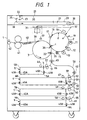
- Fig. 1 shows a whole construction of a color image forming apparatus (copying machine) according to a first embodiment of the present invention.
- second, third and fourth sheet supply cassettes 6, 7 and 9 are of the type capable of stacking and containing the maximum size sheets (normal sheet supply cassettes), and a first or uppermost sheet supply cassette 5 is of the type capable of stacking and containing sheets having a half of the maximum size or less (small-sized cassette).
- the first cassette 5 is disposed so that a supply end of the first sheet supply cassette is offset inwardly from supply ends 6A, 7A and 9A of the second, third and fourth sheet supply cassettes 6, 7 and 9 and the other end 5B of the first sheet supply cassette 5 is vertically aligned with the other ends 6B, 7B and 9B of the second, third and fourth sheet supply cassettes 6, 7 and 9.
- a sheet path 51 for the sheet supplied from the first sheet supply cassette 5 is joined to a common sheet path 56 for the sheets supplied from the second, third and fourth sheet supply cassettes 6, 7 and 9 between the supply end 5A of the first sheet supply cassette 5 and the supply end 6A of the second sheet supply cassette 6.
- a second pair of regist rollers 65 are arranged at the junction 66 between the sheet paths 51, 56.
- the junction 66 between the sheet path 51 and the common sheet path 56 is disposed below a photosensitive drum 2 for performing the image forming operation and a transfer drum 3.
- the space for forming the sheet path 51 for the first sheet supply cassette 5 is not limited by the presence of the common sheet path 56 for the second, third and fourth sheet supply cassettes 6, 7 and 9, and, accordingly, it is possible to increase the curvature of the sheet path 51.
- the installation space for the sheet supply roller 46 for the first sheet supply cassette 5 is not limited by the presence of the common sheet path 56 for the second, third and fourth sheet supply cassettes 6, 7 and 9, and, accordingly, it is possible to use the sheet supply roller 46 having the large diameter.
- the sheet supply cassette of the type capable of stacking and containing sheets having a half of the maximum size or less is used as the first sheet supply cassette 5 as in this color image forming apparatus, for example, since the a sheet mainly used in an image forming apparatus using sheets having the maximum size A3 is A4 size and the maximum size sheets can be supplied from the second, third or fourth sheet supply cassette 6, 7 and 9, there is no problem regarding the supplying of the maximum size sheet. Therefore, when the number of the sheet supply cassettes is great and there is enough margin for the supplying of the maximum size sheet, the second sheet supply cassette 6 can be constructed as same as the first sheet supply cassette 5.
- a second embodiment shown in Fig. 2 an example that the sheet supply cassettes 5, 6, 7 and 9 (sheet supply cassettes 7, 9 are omitted from illustration) are used in a normal mono-color image forming apparatus (copying machine) is shown.
- the sheet supplied from the first, second, third or fourth sheet supply cassette 5, 6, 7 or 9 is sent between a photosensitive drum 67 and a transfer charger 69 by the second pair of regist rollers 65.
- the small-sized sheet supply cassette (not containing the maximum size sheets) is used as the uppermost sheet supply cassette so that the sheet supply roller and the sheet path for the uppermost sheet supply cassette are disposed at the positions which are not influenced by the presence of the common sheet path for the other sheet supply cassettes capable of containing the maximum size sheets, it is possible to use the sheet supply roller having the greater diameter in association with the uppermost sheet supply cassette and to increase the curvature of the sheet path for the uppermost sheet supply cassette. Therefore, even when a number of sheet supply cassettes are arranged in the limited space within the image forming apparatus as much as possible, it is possible to stably supply the thick sheets having the great friction and the films having the great resiliency from the uppermost sheet supply cassette.
- This image forming apparatus includes a digital color image reader portion at its upper part, and a digital color image printer portion at its lower part.
- an original 130 is rested on an original support glass 131.
- a light image reflected from the original 130 is focused on a full-color sensor 134 by a lens 133, thereby obtaining a color decomposing image signal.
- This color decomposing signal is sent, via an amplifier circuit (not shown), to a video processing unit (not shown), where the signal is processed.
- the processed signal is sent to the printer portion.
- a photosensitive drum (image bearing member) 101 is supported for rotation in a direction shown by the arrow.
- a pre-exposure lamp 111 Around the photosensitive drum 101, there are arranged a pre-exposure lamp 111, a corona charger 102, a laser exposure optical system 103, a potential sensor 112, four different color developing devices 104y, 104c, 104m and 104Bk, a light amount detection means 113 for detecting a light amount on the photosensitive drum, a transfer device 105, and a cleaning device 106.
- the image signal from the reader portion is converted into a light image by a laser output portion (not shown), and the converted laser light is reflected by a polygon mirror 103a to be projected onto the surface of the photosensitive drum 101 through a lens 103b and a mirror 103c.
- the photosensitive drum 101 is rotated in the direction shown by the arrow. After the charge on the photosensitive drum is removed by the pre-exposure lamp 111, the photosensitive drum 101 is uniformly charged by the charger 102 and the light image E of each decomposed color is illuminated on the photosensitive drum, thereby forming a latent image.
- the latent image on the photosensitive drum 101 is developed by the corresponding developing device, thereby forming a toner image (based on resin) on the photosensitive drum 101.
- the developing devices can be selectively approached to the photosensitive drum 101 by corresponding eccentric cams 124y, 124c, 124m and 124Bk in response to the decomposed color component.
- the toner image on the photosensitive drum 101 is transferred onto a recording sheet supplied from a sheet supply cassette 107 to a position confronting to the photosensitive drum 101 by a convey means, by the transfer device 105.
- the transfer device 105 comprises a transfer drum 105a, a transfer charger 105b, an adsorption charger 105c and an adsorption roller 105g which are opposed to each other and serve to electrostatically attract the recording sheet, an inner charger 105d, and an outer charger 105e.
- a recording sheet bearing film 105f made of dielectric material is integrally attached to the transfer drum 105a (rotatably supported) to cover an opening portion of the transfer drum.
- the recording sheet bearing film 105f may be made from a dielectric sheet such as a polycarbonate film.
- the desired number of color toner images are transferred to the recording sheet carried by the recording sheet bearing sheet 105f, thereby forming a full-color image.
- the recording sheet is separated from the transfer drum 105a by a separating pawl 108a, a separation and pusher roller 108b, and a separation charger 105h.
- the separated sheet is sent to a heat roller fixing device 109 where the image is fixed to the sheet, and then the sheet is discharged onto a tray 110.
- the residual toner remaining on the photosensitive drum 101 is removed by the cleaning device 106 to prepare the drum for the next image formation.
- the sheet is temporarily introduced into a reversing path 121a through a sheet path switching guide 119 and a vertical sheet path 120. Thereafter, by rotating a reversing roller 121b reversely, the sheet is fed back in the reverse direction onto an intermediate tray 122. Then, an image is formed on the other surface of the sheet by the above-mentioned image forming operation.
- the recording sheet bearing sheet is cleaned by a fur brush 114 and a back-up brush 115 confronting to the fur brush with the interposition of the recording sheet bearing sheet 105f, and an oil removing roller 116 and a back-up brush 117 confronting to the oil removing roller with the interposition of the recording sheet bearing sheet 105f.
- Such cleaning is effected after or before the image formation, and is always effected when the sheet jam occurs.
- an eccentric cam 125 is actuated at a desired timing to drive a cam follower 105i integral with the transfer drum 105a, thereby permitting the setting of any gap between the recording sheet bearing sheet 105f and the photosensitive drum 101.
- the transfer drum is spaced apart from the photosensitive drum.
- the sheet P 1 is supplied by a pick-up roller 210 and is fed by a feed roller 211 and a retard roller 212 to advance between upper and lower guides 213, 214 and between an upper guide 215 and a movable guide 207 and between the upper guide 215 and a right guide 205 to reach a pair of regist rollers 216, 217 now stopped. Further, the sheet is further fed by about 5 mm by the rollers 211, 212 to form a loop having upward convex in the sheet P 1 as shown, and then the rollers are stopped. An amount of the loop is determined by feeding the sheet by a predetermined amount (i.e., 5 mm) after a leading end of the sheet is detected by sensors S 1 , S 2 .
- a predetermined amount i.e., 5 mm
- the pair of regist rollers 216, 217 are rotated, thereby feeding the sheet between left and right guides 219, 218 to introduce the sheet between the adsorption roller 105g and the adsorption charger 105c from slightly outward direction along the tangential line H between the transfer drum 105a and the adsorption roller 105g.
- the sheet is electrostatically adhered to the recording sheet bearing film 105f.
- the sheet may be mechanically gripped by a gripper and the like.
- the toner image on the photosensitive drum 101 is transferred onto the sheet P 1 by the transfer charger 105b disposed immediately above the adsorption roller 105g.
- a sheet P 2 fed through between guides 203, 204 is curled to have upward convex while the sheet is being passed between a sponge roller 201 and a lower roller 202.
- the sheet is further fed to pass between the right guide 205 and the movable guide 207 and between the right guide 205 and the upper guide 215 and to reach the pair of regist rollers 216, 217 now stopped.
- the reason why the sheet P 2 alone is curled is that, if there is no curl, the sheet P 2 tends to be curled in a direction that it is difficult to wind the sheet P 2 around the transfer drum while the sheet P 2 is being fed through the guides 203, 204, 205 and 207.
- the sheet path for feeding the sheet P 2 is sufficiently longer than a length of the sheet P 2 , it is easy to provide rollers for curling the sheet in the sheet path.
- the rollers 201, 202 disposed at an upstream side of the regist rollers 216, 217 serve as the rollers for curling the sheet.
- such roller for curling the sheet may be provided at an upstream side of the feed rollers 201, 202.
- the sheet P 2 tends to be curled in a direction that the sheet can easily be wound around the transfer drum, it is no need to provide any rollers for curling the sheet P 1 in the sheet path. Accordingly, since the junction between the sheet paths for the sheet P 1 , P 2 can be arranged immediately below and in the vicinity of the adsorption portions 105c, 105g of the transfer drum 105a and the sheet supply cassette 107 can be arranged at the right side of the junction, the height of the apparatus does not increase due to the presence of the sheet supply cassette 107. Further, since the uppermost sheet supply cassette is small-sized to contain small-sized sheets exclusively, the cassette does not interfere with the both-sided vertical sheet path and the width of the apparatus does not increase due to the presence of the sheet supply cassette 107.
Landscapes
- Physics & Mathematics (AREA)
- General Physics & Mathematics (AREA)
- Color Electrophotography (AREA)
- Electrostatic Charge, Transfer And Separation In Electrography (AREA)
Claims (11)
- Appareil de formation d'images, comportant :dans lequel une partie de jonction (66) entre lesdits premier et second chemins (51, 56 ; 203, 204, 213, 214) de feuille est positionnée au-dessus desdites première et seconde extrémités dans une direction verticale, et entre lesdites première et seconde extrémité dans une direction horizontale dudit appareil de formation d'images,un premier moyen de logement (6 ; 7, 9) destiné à loger en lui des feuilles ;un second moyen de logement (5 ; 107) agencé au-dessus dudit premier moyen de logement (6 ; 7, 9) et destiné à loger en lui des feuilles ;un moyen (2 ; 67 ; 101) de formation d'image agencé au-dessus dudit second moyen de logement (5 ; 107) et destiné à former une image sur la feuille ;un premier chemin (56 ; 203, 204) de feuille pour faire avancer la feuille d'une première extrémité dudit premier moyen de logement (6 ; 7, 9) jusqu'audit moyen (2 ; 67 ; 101) de formation d'image ; etun second chemin (51 ; 213, 214) de feuille destiné à faire avancer la feuille à partir d'une seconde extrémité dudit second moyen (5 ; 107) de logement et relié audit premier chemin (56 ; 203, 204) de feuille, la seconde extrémité étant positionnée du même côté que ladite première extrémité dudit premier moyen de logement (6 ; 7, 9) dans une direction horizontale dudit appareil de formation d'images ;
caractérisé en ce que
lesdits premier et second chemins (51, 56 ; 203, 204, 213, 214) de feuille sont courbés dans des directions opposées immédiatement avant ladite partie de jonction (66). - Appareil de formation d'images selon la revendication 1,
caractérisé en ce que
chacun desdits premier et second moyens de logement (5, 6, 7, 9 ; 107) comporte une cassette. - Appareil de formation d'images selon la revendication 2,
caractérisé en ce que
lesdites cassettes (5, 6, 7, 9 ; 107) peuvent être déplacées dans une direction croisant une direction d'avance de feuille dans un plan horizontal. - Appareil de formation d'images selon la revendication 1,
caractérisé en ce que
un moyen d'avance (62 ; 210, 202), destiné à faire avancer la feuille en relation de temps appropriée avec le temps de fonctionnement dudit moyen de formation d'images (2 ; 67 ; 101), est disposé en aval de ladite partie de jonction (66) dans ledit premier chemin (56 ; 203, 204) de feuille. - Appareil de formation d'images selon la revendication 1,
caractérisé en ce que
ledit moyen (2 ; 67 ; 101) de formation d'images comporte un élément porteur d'image destiné à porter une image en toner devant être reportée sur la feuille. - Appareil de formation d'images selon la revendication 5,
caractérisé en ce que
ledit moyen (2 ; 67 ; 101) de formation d'images comporte un tambour de report tournant tout en supportant la feuille pour reporter l'image en toner dudit élément porteur d'image sur la feuille. - Appareil de formation d'images selon la revendication 6,
caractérisé par
un moyen (105) destiné à appliquer par absorption la feuille sur ledit tambour de report. - Appareil de formation d'images selon la revendication 7,
caractérisé en ce que
ledit moyen (2 ; 67 ; 101) de formation d'images comprend un moyen de formation d'image en couleurs destiné à former des images en toners de couleurs respectives ayant différentes couleurs sur ledit élément porteur d'image, et les images en toners de couleurs respectives sont reportées successivement sur la feuille adhérant audit tambour de report. - Appareil de formation d'images selon la revendication 1,
caractérisé en ce que
ladite partie de jonction (66) est disposée en dessous dudit moyen (2 ; 67 ; 101) de formation d'images et au-dessus de ladite première extrémité et de ladite seconde extrémité, dans une direction verticale, dudit appareil de formation d'images. - Appareil de formation d'images selon la revendication 1,
caractérisé en ce que
ledit premier chemin (56 ; 203, 204) de feuille est courbé en une forme en U. - Appareil de formation d'images selon la revendication 1,
caractérisé en ce que
une dimension maximale de la feuille contenue dans ledit second moyen de logement (5 ; 107) est plus petite qu'une dimension maximale de la feuille contenue dans ledit premier moyen de logement (6 ; 7, 9).
Applications Claiming Priority (6)
| Application Number | Priority Date | Filing Date | Title |
|---|---|---|---|
| JP4171589A JPH05338832A (ja) | 1992-06-05 | 1992-06-05 | 画像形成装置 |
| JP17158992 | 1992-06-05 | ||
| JP171589/92 | 1992-06-05 | ||
| JP101041/93 | 1993-04-27 | ||
| JP10104193A JP3313813B2 (ja) | 1993-04-27 | 1993-04-27 | 画像形成装置 |
| JP10104193 | 1993-04-27 |
Publications (3)
| Publication Number | Publication Date |
|---|---|
| EP0573061A2 EP0573061A2 (fr) | 1993-12-08 |
| EP0573061A3 EP0573061A3 (fr) | 1995-01-25 |
| EP0573061B1 true EP0573061B1 (fr) | 2005-12-21 |
Family
ID=26441972
Family Applications (1)
| Application Number | Title | Priority Date | Filing Date |
|---|---|---|---|
| EP93109023A Expired - Lifetime EP0573061B1 (fr) | 1992-06-05 | 1993-06-04 | Appareil de formation d'images |
Country Status (3)
| Country | Link |
|---|---|
| US (1) | US5565970A (fr) |
| EP (1) | EP0573061B1 (fr) |
| DE (1) | DE69333943T2 (fr) |
Families Citing this family (16)
| Publication number | Priority date | Publication date | Assignee | Title |
|---|---|---|---|---|
| EP0666518B1 (fr) * | 1994-02-04 | 2006-06-28 | Sharp Kabushiki Kaisha | Appareil de formation d'images |
| US5933697A (en) * | 1994-03-24 | 1999-08-03 | Canon Kabushiki Kaisha | Image forming apparatus with curl generating means |
| JPH08202169A (ja) * | 1995-01-23 | 1996-08-09 | Fuji Xerox Co Ltd | 画像記録装置 |
| JPH08292700A (ja) * | 1995-02-22 | 1996-11-05 | Fuji Xerox Co Ltd | 画像形成装置の制御方式 |
| JPH0999601A (ja) * | 1995-10-04 | 1997-04-15 | Fuji Xerox Co Ltd | 画像形成装置 |
| JPH09171307A (ja) * | 1995-10-20 | 1997-06-30 | Fuji Xerox Co Ltd | 画像記録装置 |
| US5745820A (en) * | 1995-10-24 | 1998-04-28 | Sharp Kabushiki Kaisha | Image forming apparatus with a potential generating device |
| KR0181153B1 (ko) * | 1996-06-27 | 1999-04-01 | 김광호 | 용지받침 장치 |
| JPH10129883A (ja) * | 1996-10-30 | 1998-05-19 | Canon Inc | シート給送装置及び画像形成装置 |
| US5860054A (en) * | 1997-01-02 | 1999-01-12 | Xerox Corporation | Method for improving feeding of a compilations of recording sheets in printing process |
| JP2000247526A (ja) * | 1999-02-26 | 2000-09-12 | Minolta Co Ltd | 用紙カール矯正装置 |
| JP3882439B2 (ja) * | 2000-01-06 | 2007-02-14 | コニカミノルタホールディングス株式会社 | 画像形成装置 |
| US6682237B2 (en) * | 2001-09-11 | 2004-01-27 | Hewlett-Packard Development Company, L.P. | Apparatus and method for transporting print media through a printzone of a printing device |
| EP1310716B1 (fr) | 2001-11-09 | 2006-07-26 | Techspace Aero S.A. | Desaerateur |
| US6805347B2 (en) * | 2002-11-18 | 2004-10-19 | Hewlett-Packard Development Company, L.P. | Deskew mechanism and method |
| JP2016023031A (ja) * | 2014-07-18 | 2016-02-08 | キヤノン株式会社 | シート供給装置およびプリント装置 |
Citations (1)
| Publication number | Priority date | Publication date | Assignee | Title |
|---|---|---|---|---|
| US5168316A (en) * | 1990-03-13 | 1992-12-01 | Kabushiki Kaisha Toshiba | Sheer feeding control mechanism for an image forming apparatus |
Family Cites Families (15)
| Publication number | Priority date | Publication date | Assignee | Title |
|---|---|---|---|---|
| US3920238A (en) * | 1972-10-16 | 1975-11-18 | Canon Kk | Copy medium feed device |
| US3963339A (en) * | 1974-09-05 | 1976-06-15 | Xerox Corporation | Sheet feeding apparatus |
| JPS567937U (fr) * | 1979-06-28 | 1981-01-23 | ||
| US4366219A (en) * | 1981-01-08 | 1982-12-28 | Xerox Corporation | Scanning optics copier with variable pitch copy capability |
| ZA836666B (en) * | 1982-09-21 | 1984-06-27 | Xerox Corp | Sheet feeding apparatus |
| JPS6129860A (ja) * | 1984-07-23 | 1986-02-10 | Fuji Xerox Co Ltd | カラ−電子複写機の転写装置 |
| US4627711A (en) * | 1985-09-30 | 1986-12-09 | Xerox Corporation | Machine shutdown control |
| JPS6438345A (en) * | 1987-07-31 | 1989-02-08 | Toshiba Corp | Picture forming device |
| JP2638850B2 (ja) * | 1987-11-05 | 1997-08-06 | 富士ゼロックス株式会社 | フルカラー電子写真画像形成装置 |
| JP2607117B2 (ja) * | 1988-04-05 | 1997-05-07 | キヤノン株式会社 | 画像形成装置 |
| JPH0745291B2 (ja) * | 1989-05-15 | 1995-05-17 | シャープ株式会社 | 給紙装置 |
| EP0400996B1 (fr) * | 1989-05-31 | 1994-05-11 | Canon Kabushiki Kaisha | Appareil de formation d'images |
| JP2977210B2 (ja) * | 1989-08-30 | 1999-11-15 | 株式会社東芝 | 給紙装置 |
| JP2744315B2 (ja) * | 1990-02-06 | 1998-04-28 | キヤノン株式会社 | 画像形成装置 |
| US5319433A (en) * | 1992-05-18 | 1994-06-07 | Canon Kabushiki Kaisha | Electrophotographing apparatus for forming color image |
-
1993
- 1993-06-04 DE DE69333943T patent/DE69333943T2/de not_active Expired - Fee Related
- 1993-06-04 EP EP93109023A patent/EP0573061B1/fr not_active Expired - Lifetime
-
1995
- 1995-04-26 US US08/429,025 patent/US5565970A/en not_active Expired - Fee Related
Patent Citations (1)
| Publication number | Priority date | Publication date | Assignee | Title |
|---|---|---|---|---|
| US5168316A (en) * | 1990-03-13 | 1992-12-01 | Kabushiki Kaisha Toshiba | Sheer feeding control mechanism for an image forming apparatus |
Also Published As
| Publication number | Publication date |
|---|---|
| DE69333943T2 (de) | 2006-08-03 |
| DE69333943D1 (de) | 2006-01-26 |
| US5565970A (en) | 1996-10-15 |
| EP0573061A2 (fr) | 1993-12-08 |
| EP0573061A3 (fr) | 1995-01-25 |
Similar Documents
| Publication | Publication Date | Title |
|---|---|---|
| EP0573061B1 (fr) | Appareil de formation d'images | |
| US4941021A (en) | Image forming apparatus with recording material loop forming and control means | |
| US8095059B2 (en) | Image forming apparatus with coating mode | |
| US4928127A (en) | Sheet circulation in a duplex printer | |
| JP2010139603A (ja) | 画像形成装置 | |
| EP1215544B1 (fr) | Méthode et appareil de formation d'une image | |
| US5867181A (en) | Image forming apparatus for forming image on single sheet by different recording methods | |
| EP0418086B1 (fr) | Imprimante et cassette avec alimentation de feuilles orientées le bord court en avant pour copie recto-verso munies d'un inverseur avec déplacement latéral | |
| JP3877367B2 (ja) | 画像形成装置 | |
| US5842095A (en) | Image forming device with multiple image forming units | |
| EP0593023B1 (fr) | Appareil de formation d'images muni d'un élément porteur du matériau d'enregistrement | |
| US5073801A (en) | Color image forming apparatus having different ejection parts for different paper thickness | |
| EP0407152B1 (fr) | Dispositif pour empiler des feuilles | |
| US5765094A (en) | Apparatus for holding recording sheets on an image recording apparatus | |
| US7251450B2 (en) | Paper separator and processor cartridge | |
| JPH05341600A (ja) | 画像形成装置 | |
| US7722040B2 (en) | Sheet carrying device and sheet carrying method for image forming apparatus | |
| JPH07172639A (ja) | シート材搬送装置及び画像記録装置 | |
| US5331389A (en) | Image forming apparatus with sheet discharging device | |
| JP4031923B2 (ja) | 画像形成装置及び画像形成方法 | |
| EP0974874B1 (fr) | Appareil de formation d'images | |
| EP1679557B1 (fr) | Appareil de formation d'images avec une bande de transfert intermédiaire aux fluctuations limitées de la vitesse | |
| JP4139060B2 (ja) | 画像形成装置 | |
| EP0617341B1 (fr) | Séparation de papier des bandes de photorécepteurs avec contrainte réduite | |
| JP2003173091A (ja) | 画像形成装置 |
Legal Events
| Date | Code | Title | Description |
|---|---|---|---|
| PUAI | Public reference made under article 153(3) epc to a published international application that has entered the european phase |
Free format text: ORIGINAL CODE: 0009012 |
|
| AK | Designated contracting states |
Kind code of ref document: A2 Designated state(s): DE FR GB IT |
|
| PUAL | Search report despatched |
Free format text: ORIGINAL CODE: 0009013 |
|
| AK | Designated contracting states |
Kind code of ref document: A3 Designated state(s): DE FR GB IT |
|
| 17P | Request for examination filed |
Effective date: 19950612 |
|
| 17Q | First examination report despatched |
Effective date: 19970108 |
|
| GRAP | Despatch of communication of intention to grant a patent |
Free format text: ORIGINAL CODE: EPIDOSNIGR1 |
|
| GRAS | Grant fee paid |
Free format text: ORIGINAL CODE: EPIDOSNIGR3 |
|
| GRAA | (expected) grant |
Free format text: ORIGINAL CODE: 0009210 |
|
| AK | Designated contracting states |
Kind code of ref document: B1 Designated state(s): DE FR GB IT |
|
| PG25 | Lapsed in a contracting state [announced via postgrant information from national office to epo] |
Ref country code: IT Free format text: LAPSE BECAUSE OF FAILURE TO SUBMIT A TRANSLATION OF THE DESCRIPTION OR TO PAY THE FEE WITHIN THE PRESCRIBED TIME-LIMIT;WARNING: LAPSES OF ITALIAN PATENTS WITH EFFECTIVE DATE BEFORE 2007 MAY HAVE OCCURRED AT ANY TIME BEFORE 2007. THE CORRECT EFFECTIVE DATE MAY BE DIFFERENT FROM THE ONE RECORDED. Effective date: 20051221 |
|
| REG | Reference to a national code |
Ref country code: GB Ref legal event code: FG4D |
|
| REF | Corresponds to: |
Ref document number: 69333943 Country of ref document: DE Date of ref document: 20060126 Kind code of ref document: P |
|
| PG25 | Lapsed in a contracting state [announced via postgrant information from national office to epo] |
Ref country code: GB Free format text: LAPSE BECAUSE OF NON-PAYMENT OF DUE FEES Effective date: 20060604 |
|
| ET | Fr: translation filed | ||
| PLBE | No opposition filed within time limit |
Free format text: ORIGINAL CODE: 0009261 |
|
| STAA | Information on the status of an ep patent application or granted ep patent |
Free format text: STATUS: NO OPPOSITION FILED WITHIN TIME LIMIT |
|
| 26N | No opposition filed |
Effective date: 20060922 |
|
| GBPC | Gb: european patent ceased through non-payment of renewal fee |
Effective date: 20060604 |
|
| PGFP | Annual fee paid to national office [announced via postgrant information from national office to epo] |
Ref country code: DE Payment date: 20070731 Year of fee payment: 15 |
|
| PGFP | Annual fee paid to national office [announced via postgrant information from national office to epo] |
Ref country code: FR Payment date: 20070522 Year of fee payment: 15 |
|
| REG | Reference to a national code |
Ref country code: FR Ref legal event code: ST Effective date: 20090228 |
|
| PG25 | Lapsed in a contracting state [announced via postgrant information from national office to epo] |
Ref country code: DE Free format text: LAPSE BECAUSE OF NON-PAYMENT OF DUE FEES Effective date: 20090101 |
|
| PG25 | Lapsed in a contracting state [announced via postgrant information from national office to epo] |
Ref country code: FR Free format text: LAPSE BECAUSE OF NON-PAYMENT OF DUE FEES Effective date: 20080630 |