EP0572392B1 - Appareil d'emballage de balles - Google Patents
Appareil d'emballage de balles Download PDFInfo
- Publication number
- EP0572392B1 EP0572392B1 EP91906165A EP91906165A EP0572392B1 EP 0572392 B1 EP0572392 B1 EP 0572392B1 EP 91906165 A EP91906165 A EP 91906165A EP 91906165 A EP91906165 A EP 91906165A EP 0572392 B1 EP0572392 B1 EP 0572392B1
- Authority
- EP
- European Patent Office
- Prior art keywords
- bale
- rotation
- film
- wrapper apparatus
- platform
- Prior art date
- Legal status (The legal status is an assumption and is not a legal conclusion. Google has not performed a legal analysis and makes no representation as to the accuracy of the status listed.)
- Expired - Lifetime
Links
Images


Classifications
-
- A—HUMAN NECESSITIES
- A01—AGRICULTURE; FORESTRY; ANIMAL HUSBANDRY; HUNTING; TRAPPING; FISHING
- A01F—PROCESSING OF HARVESTED PRODUCE; HAY OR STRAW PRESSES; DEVICES FOR STORING AGRICULTURAL OR HORTICULTURAL PRODUCE
- A01F15/00—Baling presses for straw, hay or the like
- A01F15/07—Rotobalers, i.e. machines for forming cylindrical bales by winding and pressing
- A01F15/071—Wrapping devices
- A01F2015/0725—Film dispensers for film rollers in a satellite type wrapper, e.g. holding and tensioning means for the film roller
-
- A—HUMAN NECESSITIES
- A01—AGRICULTURE; FORESTRY; ANIMAL HUSBANDRY; HUNTING; TRAPPING; FISHING
- A01F—PROCESSING OF HARVESTED PRODUCE; HAY OR STRAW PRESSES; DEVICES FOR STORING AGRICULTURAL OR HORTICULTURAL PRODUCE
- A01F15/00—Baling presses for straw, hay or the like
- A01F15/07—Rotobalers, i.e. machines for forming cylindrical bales by winding and pressing
- A01F15/071—Wrapping devices
- A01F2015/0755—Configuration of support surfaces which can move in order to rotate a bale around at least one axis while wrapping
Definitions
- This invention relates to a wrapper apparatus for applying a stretchable plastics film around a bale of rectangular cross section in order to form a substantially air tight and water tight wrapping around the bale.
- bales are cylinders of circular cross section
- This technique is employed in order to form a weather proof protective wrapping which can maintain the bale material in a dry state in the case of dried material, such as straw or hay.
- the technique may be used to seal the bale contents from contact with atmospheric oxygen so that wet or damp bale material, such as newly cut and baled grass, or ammonium treated straw can ferment over a period of time to form silage.
- silage within wrapped round bales is gaining wide acceptance by farmers and contractors, because it avoids the costs of installing expensive silage towers.
- One well known machine comprises the Silawrap bale wrapper apparatus manufactured by Kverneland Underhaug AS of Naerbo, Norway, and which is protected by GB patent No 2159489B, and other still pending patent applications.
- the Silawrap machine comprises a turntable which rotates about a substantially vertical axis, and on which is mounted a pair of laterally spaced substantially horizontal rollers which support a cylindrical bale by means of one or more slack belts taken around the rollers, and at least one of which rollers is driven in order to rotate the bale about its longitudinal axis.
- the end of a length of stretchable plastics film is applied to the bale manually, or by automatic apparatus e.g. the cut and tie mechanism which forms the subject of EP 0367529A, and the combined rotations of the bale about both vertical and horizontal axes causes a helical winding of film to be applied around the bale, with successive turns partially overlapping until such time as the bale is completely covered twice over.
- bales are usually stacked, and undergo some deformation during handling and storage, and especially when silage is being produced during storage.
- the Silawrap machine When operated properly, the Silawrap machine is able to apply reliable wrapping around bales of long stem and other agricultural material, provided that the bales are supplied in the substantially cylindrical form, so that the bales can be rotated at substantially uniform speed about their longitudinal axes.
- the extent of overlap of successive windings will depend upon the size of the bale, the width of the film and the ratio of the speeds of revolution of the platform about the vertical axis and of the bale about the horizontal axis.
- balers which produce rectangular section bales are generally able to produce a denser bale by virtue of the piston type compression action involved to produce the bale, and therefore less storage space is required as the weight / volume ratio of rectangular section bales can be higher than that of cylindrical bales.
- rectangular section bales can be transported and stored more efficiently than cylindrical bales, because they are able to fit together with less voids between them.
- a rectangular section bale cannot readily be rotated about a horizontal axis in the same way as a cylindrical bale, which has a circular outer periphery and which is engaged throughout a major part of this periphery at any one time by the rollers and the slack belts running over the rollers.
- variable rotational speed of the bale about the horizontal axis arises, at least in part, because the rectangular cross section is non-square i.e. the length is greater than the width of the cross section, and also because of the difficulties of engaging the outer periphery of the rotating bale in a way so as to apply a substantially uniform rate of angular speed about a generally horizontal axis.
- the invention is based on the surprising discovery that a rotating platform type of bale wrapper apparatus e.g. of the type suitable for wrapping a cylindrical bale, can be modified so as to apply pre-stretched film wrapping around a bale of rectangular cross section in an acceptable manner.
- the invention therefore enables many of the features of the well proven design of bale wrapper apparatus for cylindrical bales to be used in the wrapping of rectangular cross section bales.
- a bale wrapper apparatus for applying a pre-stretched film around a bale of rectangular cross section in order to form a substantially air tight and water tight wrapping around the bale and which comprises: a platform which is rotatable about a substantially vertical axis; a pair of rollers mounted on the platform for rotation about substantially horizontal axes and laterally spaced apart from each other; one or more endless slack belts taken around the rollers and defining a trough shape into which the rectangular section of the bale can be received with the upper and lower sides of the bale disposed in substantially horizontal planes, the arrangement being such that upon the application of drive to at least one of the rollers, the belt(s) can cause the bale to carry out a rotary tumbling action about a substantially horizontal axis; a support for mounting a film dispenser reel from which film can be withdrawn for attachment to the bale prior to wrapping of the film around the bale; a pre-stretcher mechanism engageable with the film as it passes
- one dimension of the rectangular cross section (the length) will usually be greater than the other dimension (the width)
- the guide being arranged in the path of rotation of the edge regions of the longer sides, such edge regions are held away from contact with said one roller while the adjacent upstream edge of the bale is engaged and conveyed forwardly by the belt and therefore forms the instantaneous centre of rotation of the bale until such time as the bale moves out of engagement with the guide.
- the guide may comprise a guide roller carried by an arm which is mounted on the platform for rotation therewith.
- the roller may be biased by any suitable means e.g. a spring arrangement to a position which lies in the path of the edge regions of the longer sides of the bale cross section.
- a guide plate which may be fixed, or which may be able to yield against resilient opposition when engaged by the bale during its rotation.
- a number of slack belts are taken over the rollers and are spaced apart along their lengths, in order to define the trough shape in which the bale can be received.
- At least one of the belts is ribbed.
- bale wrapper apparatus One embodiment of bale wrapper apparatus according to the invention will now be described in detail, by way of example only, with reference to the accompanying drawing, in which:
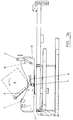
- bale wrapper apparatus is designated generally by reference 10 and is intended to apply a pre-stretched plastics film 11 around a bale 12 of rectangular cross section in order to form a substantially air tight and water tight wrapping around the bale.
- the apparatus 10 comprises a chassis 12a having a towing hitch 13 at its forward end for attachment to a propelling vehicle, and provided with a set of wheels 14 at its rear end.
- a platform 15 is mounted on the chassis 12 for rotation about a substantially vertical axis 16, and a pair of rollers 17 and 18 are mounted on the platform 15 for rotation about substantially horizontal axes 19, the rollers 17 and 18 being laterally spaced apart from each other in order to receive the bale 12 therebetween.
- a number of slack belts 20 and 21 are taken around the rollers 17 and 18 and define a trough shape into which the rectangular sect ion of the bale 12 can be received, as shown in full lines in Figure 1, and in which the upper side 22 and lower side 23 of the bale are disposed in substantially horizontal planes. It will be noted from Figure 1 that the lower side 23 is located between the rollers 17 and 18, and at a lower level than the horizontal plane passing through the upper regions of the rollers 17 and 18.
- the roller 17 is a driven roller, and the arrangement is such that the belts 20 and 21 can cause the bale to carry out a rotary tumbling action in the direction of the arrow shown in Figure 1 about a generally horizontal axis.
- the full line position of the bale 12 shown in Figure 1 shows the starting position, and the dashed outline shows the position taken-up by the bale after rotation through approximately 135 o .
- a support 24 is mounted on the chassis 12a and carries a film dispenser reel 25 and an associated film pre-stretcher mechanism 26 which engages with the film as it is withdrawn from the reel 25 and passes to the bale 12, this mechanism being operable to stretch the film prior to its application around the bale upon rotation of platform 15 about axis 16 and rotation of the bale about a generally horizontal axis upon operation of the rollers 17 and 18 and slack belts 20 and 21.
- the pre-stretcher mechanism may be as disclosed in more detail in EP No 0291483.
- a guide 27 is arranged above the drive roller 17 in order to engage intermittently with portions of the outer periphery of the rotating bale, and specifically with the edge regions 28 of the longer sides 29 of the rectangular section of the bale.
- the purpose of the guide is to prevent the edge portions 28 falling under gravity onto the roller 17, and in addition to retard the instantaneous speed of rotation of the bale at this phase in each revolution by remaining in engagement with the bale while the bale is further rotated by the belt.
- the geometry of the system is such that a generally uniform rate of tumbling rotation is applied to the bale, despite the fact that it has a rectangular cross section.
- each of the edge regions 28 of the longer sides 29 will come into contact with the guide arrangements 27, and at that time the adjacent upstream edge 30 of the bale is engaged and conveyed forwardly by the belts thereby forming an instantaneous centre of rotation of the bale, until such time as the edge regions 28 slide out of engagement with the guide arrangement 27.
- the roller 31 will engage the bale side at or near to the corner of the bale, but the "edge region” engaged may extend away from the corner by a distance up to less than half way along the bale side).
- the arrangement of the slack belts allows the edge 30 to descend to a lower level than that of lower side 23 of the bale when in the horizontal attitude.
- the guide 27 comprises a guide roller 31 carried by an arm 32 which is pivotally mounted on the platform 15 for rotation therewith.
- the roller 31 may be biased in a clockwise direction as shown by any suitable means e.g. a spring arrangement, to a position which lies in the path of the edge regions 28 of the longer sides 29 of the bale cross section.
- suitable means e.g. a spring arrangement
- guide plate not shown
- four sets of slack belts 20 and 21 are provided, arranged in pairs, and preferably at least one of the belts in each pair is ribbed in order to improve the gripping engagement with the outer periphery of the bale.
- Usual frusto-conical guides 32 are mounted on the platform 15 adjacent each end of the bale 12 to guide the latter during its rotation.
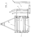
- this shows a modified arrangement according to the invention, which is capable of supporting and of controlling the rotation of a rectangular bale, so as to maintain the rotation of the bale at a substantially uniform rate, despite the fact that it is of rectangular cross section, and is supported on a platform which may have been designed originally in order to support and to rotate a circular cross section bale.
- a support roll 1 which is adjustable on a leaf spring 3, and which engages the side of the rotating bale in order to control its rate of rotation.
- a support roll 2 which is adjustable in height, as shown in Figures 3a and 3b, and which also may be used to control the rotation of a rectangular section bale, and especially a larger bale than that shown in the drawing.
- damper 4 mounted on the platform, and which is able to absorb the impact of the rotating bale. Further, the instantaneous point of support 7 of a rectangular bale 8 is horizontally adjustable, as shown by arrows 9.
- the tension of the slack belts (taken around the rollers 17 and 18 in Figures 1 and 2) is adjusted to a level sufficient to achieve substantially uniform rotation of the rectangular (square) bale, depending upon the dimensions of the bale.
- adjustment of the tension of the belts will alter the profile of the trough shape which the belts will take-up (in the absence of any load thereon), and this will influence the manner by which the bale is supported on the belts and then caused to rotate.
- the bale 8 has an instantaneous engagement with the belts along a line, and which forms an instantaneous centre of rotation of the bale.
- the spring supported roll 1 functions in generally similar manner to that described above for roll 31 in Figures 1 and 2, but the arrangement shown in Figures 3 and 4 provides improved control over the rate of rotation of the bale 8 about a generally horizontal axis, thereby to provide more uniform overlapping webs of wrapping material around the bale during combined rotation of the bale about vertical and horizontal axes while film is withdrawn from the stationary film dispenser reel.
- Typical bale dimensions of rectangular (or square) bales which can be successfully wrapped comprise: 90 x 90 x 160 cm; 90 x 80 x 160 cm; 80 x 80 x 160 cm; 80 x 70 x 160 cm; and 70 x 70 x 160 cm.
- the instantaneous centre of rotation 7 of bale 8 can be horizontally adjusted, in order to suit the dimensions of any particular square or rectangular bale which is to be wrapped.
- Figure 5 shows one arrangement whereby this horizontal adjustment of the instantaneous centre of rotation 7a can be adjusted, which comprises the provision of means for adjusting the axis 19a of one of the platform rollers 17a or 18a, whereby to vary the position of the instantaneous centre of rotation.
- Figure 5 also shows an alternative arrangement for the frusto-conical end guides 32 of Figures 1 and 2, which engage the opposed end faces of the bale in order to maintain it in position on the platform during rotation of the bale.
- end guides 32a are provided which have their axis of rotation 32b angularly off-set with respect to a vertical line 33 extending upwardly from the instantaneous centre of rotation 7a. It has been found that this gives improved guidance to the opposed end faces of the bale during its rotation.
Landscapes
- Life Sciences & Earth Sciences (AREA)
- Environmental Sciences (AREA)
- Storage Of Harvested Produce (AREA)
Abstract
Claims (14)
- Appareil (10) d'emballage de balles pour appliquer un film préétiré (11) autour d'une balle (12) de section transversale rectangulaire afin de former un emballage substantiellement imperméable à l'air et imperméable à l'eau autour de la balle et qui comprend :
une plate-forme (15) qui est capable de tourner autour d'un axe (16) substantiellement vertical ;
deux rouleaux (17, 18) montés sur la plate-forme (15) pour tourner autour d'axes substantiellement horizontaux (19) et séparés latéralement l'un de l'autre ;
une ou plusieurs courroies lâches (20, 21) prises autour des rouleaux (17, 18) et définissant une forme de gouttière dans laquelle la section rectangulaire de la balle peut être reçue avec les côtés supérieur (22) et inférieur (23) de la balle placés dans des plans substantiellement horizontaux, l'agencement étant tel qu'à l'application d'une commande à au moins un des rouleaux (17), les courroies (20, 21) peuvent entraîner la balle (12) à réaliser une action tournante de culbutage autour d'un axe substantiellement horizontal ;
un support (24) pour monter une bobine (25) de distributeur de film de laquelle un film (11) peut être retiré pour être fixé à la balle (12) avant l'emballage du film autour de la balle ;
un mécanisme de préétirement (26) pouvant être mis en prise avec le film (11) alors qu'il passe de la bobine (25) à la balle (12) et pouvant être actionné pour étirer le film avant son application autour de la balle lors de la rotation de la plate-forme (15) autour de son axe (16) et lors de la rotation de la balle (12) par les courroies (20, 21) ; et
un guide (27) disposé au-dessus d'un des rouleaux (17) afin de se mettre en prise par intermittence avec des parties (28) sur la périphérie extérieure de la balle en rotation (12) pour empêcher, de ce fait, ces parties de tomber sous l'effet de la gravité sur ledit premier rouleau (17) et aussi pour retarder la vitesse instantanée de rotation de la balle en restant en prise avec la balle tandis que la balle est davantage tournée par les courroies (20, 21), pour agir de ce fait de façon à maintenir une vitesse de rotation de la balle généralement uniforme. - Appareil d'emballage de balles selon la revendication 1, dans lequel le guide (27) comprend un rouleau de guidage (31) supporté par un bras (32) qui est monté sur la plate-forme (15) pour rotation avec celle-ci.
- Appareil d'emballage de balles selon la revendication 2, dans lequel le rouleau (31) est appliqué selon une position se trouvant dans le trajet des régions de bord (28) des plus longs côtés (22, 23) de la section transversale de la balle.
- Appareil d'emballage de balles selon la revendication 1, dans lequel le guide comprend une plaque de guidage.
- Appareil d'emballage de balles selon la revendication 4, dans lequel la plaque de guidage est fixe.
- Appareil d'emballage de balles selon la revendication 4, dans lequel la plaque de guidage est agencée pour fléchir face à une opposition élastique quand elle est en prise avec la balle pendant sa rotation.
- Appareil d'emballage de balles selon l'une quelconque des revendications précédentes, comprenant une pluralité de courroies lâches (20, 21) prises autour des rouleaux et séparées le long de la longueur des rouleaux.
- Appareil d'emballage de balles selon la revendication 7, dans lequel au moins une des courroies (21) est striée afin d'améliorer la prise par serrage avec la périphérie extérieure de la balle en rotation.
- Appareil d'emballage de balles selon la revendication 1, dans lequel le guide comprend un rouleau de guidage (1) monté sur un ressort à lames (3) qui est agencé pour fléchir dans une direction vers ledit premier rouleau (17) quand il est en prise avec la balle en rotation (8).
- Appareil d'emballage de balles selon la revendication 9, dans lequel un rouleau de support (2) est monté sur la plate-forme (15) au-dessus de l'autre rouleau (18) pour contrôler la rotation de plus grandes balles.
- Appareil d'emballage de balles selon la revendication 10, dans lequel le rouleau de support (2) est ajustable en hauteur par rapport à la plate-forme (15).
- Appareil d'emballage de balles selon l'une quelconque des revendications 9 à 11, dans lequel le centre instantané de rotation (7) de la balle (8) sur les courroies (20, 21) est ajustable horizontalement.
- Appareil d'emballage de balles selon la revendication 12, dans lequel l'axe (19a) d'au moins un des rouleaux (17a, 18a) de plate-forme est ajustable afin de modifier la position du centre instantané de rotation (7a).
- Appareil d'emballage de balles selon la revendication 13, dans lequel des guides d'extrémité (32a) sont montés sur la plate-forme (15a) pour être en prise avec les extrémités de la balle (8) et qui ont leurs axes de rotation (32b) décalés de manière angulaire par rapport à une ligne verticale (33) s'étendant vers le haut à partir du centre instantané de rotation (7a).
Applications Claiming Priority (5)
| Application Number | Priority Date | Filing Date | Title |
|---|---|---|---|
| GB9005782 | 1990-03-14 | ||
| GB909005782A GB9005782D0 (en) | 1990-03-14 | 1990-03-14 | Bale wrapper apparatus |
| GB909024321A GB9024321D0 (en) | 1990-03-14 | 1990-11-08 | Bale wrapper apparatus |
| GB9024321 | 1990-11-08 | ||
| PCT/GB1991/000398 WO1991013540A1 (fr) | 1990-03-14 | 1991-03-14 | Appareil d'emballage de balles |
Publications (2)
| Publication Number | Publication Date |
|---|---|
| EP0572392A1 EP0572392A1 (fr) | 1993-12-08 |
| EP0572392B1 true EP0572392B1 (fr) | 1996-06-12 |
Family
ID=26296788
Family Applications (1)
| Application Number | Title | Priority Date | Filing Date |
|---|---|---|---|
| EP91906165A Expired - Lifetime EP0572392B1 (fr) | 1990-03-14 | 1991-03-14 | Appareil d'emballage de balles |
Country Status (3)
| Country | Link |
|---|---|
| EP (1) | EP0572392B1 (fr) |
| DE (1) | DE69120296T2 (fr) |
| WO (1) | WO1991013540A1 (fr) |
Cited By (2)
| Publication number | Priority date | Publication date | Assignee | Title |
|---|---|---|---|---|
| KR20190090921A (ko) * | 2018-01-26 | 2019-08-05 | 유한회사 대성이엔지 | 사료 랩핑방법 |
| FR3125544A1 (fr) * | 2021-07-22 | 2023-01-27 | Automatismes C.G | Table de préparation pour balles de fibres enrubannées ou ficelées |
Families Citing this family (13)
| Publication number | Priority date | Publication date | Assignee | Title |
|---|---|---|---|---|
| IE70310B1 (en) * | 1991-05-13 | 1996-11-13 | Idough Investment Co | A bale wrapping machine |
| NO176133C (no) * | 1991-11-22 | 1997-10-15 | Tellefsdal As | Innretning ved en pakkemaskin for emballering av en stråfôrballe |
| DE4201856A1 (de) * | 1992-01-24 | 1992-06-11 | Herrmann Bestmann | Foliensparendes verfahren zum verpacken von quaderfoermigen silage-ballen |
| FR2687280B1 (fr) * | 1992-02-10 | 1996-08-23 | Doucet Bernard | Systeme deflecteur de balle en sortie de machine a enrubanner les balles de paille, fourrage et ensilage. |
| FR2687040B1 (fr) * | 1992-02-10 | 1994-05-06 | Doucet Freres Sa | Machine a enrubanner des objets parallelepipediques ou rectangulaires ou cylindriques, notamment des balles de paille, fourrage, ensilage. |
| SE500211C2 (sv) * | 1992-04-03 | 1994-05-09 | Rekordverken Ab | Anordning för att vrida runt föremål |
| DE4227145C2 (de) * | 1992-08-18 | 1995-11-30 | Agritechnik Ing Betrieb | Vorrichtung zum Einwickeln von Rechteckballen |
| FI940646A0 (fi) * | 1993-04-07 | 1994-02-11 | Kalle Kivelae | Foerfarande och anordning foer att veckla in ett stycke |
| AT407143B (de) * | 1993-07-20 | 2000-12-27 | Goeweil Herbert | Wickelmaschine zum umwickeln quaderförmiger gutballen mit hüllfolien od. dgl. |
| SE503043C2 (sv) * | 1995-01-18 | 1996-03-18 | Staffan Soederberg | Förfarande och anordning vid emballering medelst banformigt material |
| IES970777A2 (en) | 1997-07-25 | 1999-01-13 | Arboc Ltd | A bale wrapping machine |
| DE59902174D1 (de) * | 1998-08-03 | 2002-09-05 | Ford New Holland Nv | Vorrichtung zum Umwickeln einer Rundballe |
| CN111994330A (zh) * | 2020-08-17 | 2020-11-27 | 江苏沃得农业机械股份有限公司 | 一种棉花圆捆打包缠膜装置 |
Family Cites Families (4)
| Publication number | Priority date | Publication date | Assignee | Title |
|---|---|---|---|---|
| US4195958A (en) * | 1978-05-30 | 1980-04-01 | Wayne Diekemper | Bale unroller |
| NZ207957A (en) * | 1984-04-26 | 1987-03-06 | Kennedy Farm Equip | Feedout apparatus for round hay bales;teasing roll loosens wound-up material |
| NZ222693A (en) * | 1986-11-27 | 1990-03-27 | Lister Taylor Ltd | Apparatus for wrapping large load with strip material |
| DE9004354U1 (de) * | 1990-04-14 | 1990-06-21 | Gebrüder Welger GmbH & Co KG, 3340 Wolfenbüttel | Vorrichtung zum Umwickeln von Ballen aus landwirtschaftlichem Halmgut |
-
1991
- 1991-03-14 DE DE69120296T patent/DE69120296T2/de not_active Expired - Fee Related
- 1991-03-14 WO PCT/GB1991/000398 patent/WO1991013540A1/fr not_active Ceased
- 1991-03-14 EP EP91906165A patent/EP0572392B1/fr not_active Expired - Lifetime
Non-Patent Citations (1)
| Title |
|---|
| "Das Folienwickel-verfahren zum Silieren von Rundballen", pages 456-459 * |
Cited By (2)
| Publication number | Priority date | Publication date | Assignee | Title |
|---|---|---|---|---|
| KR20190090921A (ko) * | 2018-01-26 | 2019-08-05 | 유한회사 대성이엔지 | 사료 랩핑방법 |
| FR3125544A1 (fr) * | 2021-07-22 | 2023-01-27 | Automatismes C.G | Table de préparation pour balles de fibres enrubannées ou ficelées |
Also Published As
| Publication number | Publication date |
|---|---|
| DE69120296T2 (de) | 1997-02-06 |
| DE69120296D1 (de) | 1996-07-18 |
| WO1991013540A1 (fr) | 1991-09-19 |
| EP0572392A1 (fr) | 1993-12-08 |
Similar Documents
| Publication | Publication Date | Title |
|---|---|---|
| EP0572392B1 (fr) | Appareil d'emballage de balles | |
| US4173112A (en) | Apparatus for wrapping a cover material around round bales | |
| US6971220B1 (en) | Method of wrapping a round bale compacted by a round baler, film-wrapping device and round baler that is provided with such a film-wrapping device | |
| KR101866576B1 (ko) | 바인딩 장치 및 베일을 바인딩하기 위한 방법 | |
| US4685270A (en) | Process for continuous wrapping an object and machine for carrying out the process | |
| US5195296A (en) | Wrapping method | |
| US6467237B2 (en) | Large round baler | |
| US4296595A (en) | Apparatus for wrapping a cover material around round bales | |
| EP0578718B1 (fr) | Procede d'enveloppement d'une botte dans deux couches croisees a tours helicoidaux chevauchants | |
| WO1994001997A1 (fr) | Appareil d'empaquetage de balles | |
| JPS6158522A (ja) | 収穫物より成るロール形ベールに帯材を巻付けて梱包し放出する方法 | |
| US6311459B1 (en) | Device and method for loading film on machines for wrapping products | |
| EP2647282B1 (fr) | Ramasseuse-presse et procédé de formation d'une balle | |
| AU8277587A (en) | Wrapping apparatus | |
| US5152125A (en) | Apparatus for wrapping articles | |
| KR102578521B1 (ko) | 베일 래핑 장치 및 농업용 베일 래핑 방법 | |
| EP1321028B1 (fr) | Presse avec un appareil pour envelopper des balles | |
| GB2090560A (en) | Agricultural baling machine | |
| CN105460262A (zh) | 圆捆捆扎装置 | |
| CN119156981A (zh) | 用于农业系统的捆包系统 | |
| US10813291B2 (en) | Round baler having an adjustable width | |
| CN103688689B (zh) | 一种草料捆扎包装系统 | |
| EP0474719A1 (fr) | Appareil pour l'emballage de balles | |
| EP0291483B1 (fr) | Dispositif de pré-étirage pour commander l'alimentation d'un film plastique étirable | |
| EP1516525B1 (fr) | Presse à balles rondes avec dispositif d'enrubannage |
Legal Events
| Date | Code | Title | Description |
|---|---|---|---|
| PUAI | Public reference made under article 153(3) epc to a published international application that has entered the european phase |
Free format text: ORIGINAL CODE: 0009012 |
|
| 17P | Request for examination filed |
Effective date: 19920929 |
|
| AK | Designated contracting states |
Kind code of ref document: A1 Designated state(s): DE DK FR GB |
|
| 17Q | First examination report despatched |
Effective date: 19950420 |
|
| GRAH | Despatch of communication of intention to grant a patent |
Free format text: ORIGINAL CODE: EPIDOS IGRA |
|
| GRAA | (expected) grant |
Free format text: ORIGINAL CODE: 0009210 |
|
| AK | Designated contracting states |
Kind code of ref document: B1 Designated state(s): DE DK FR GB |
|
| PG25 | Lapsed in a contracting state [announced via postgrant information from national office to epo] |
Ref country code: DK Effective date: 19960612 |
|
| REF | Corresponds to: |
Ref document number: 69120296 Country of ref document: DE Date of ref document: 19960718 |
|
| ET | Fr: translation filed | ||
| PG25 | Lapsed in a contracting state [announced via postgrant information from national office to epo] |
Ref country code: GB Effective date: 19970314 |
|
| PGFP | Annual fee paid to national office [announced via postgrant information from national office to epo] |
Ref country code: DE Payment date: 19970321 Year of fee payment: 7 |
|
| PLBE | No opposition filed within time limit |
Free format text: ORIGINAL CODE: 0009261 |
|
| STAA | Information on the status of an ep patent application or granted ep patent |
Free format text: STATUS: NO OPPOSITION FILED WITHIN TIME LIMIT |
|
| 26N | No opposition filed | ||
| GBPC | Gb: european patent ceased through non-payment of renewal fee |
Effective date: 19970314 |
|
| PG25 | Lapsed in a contracting state [announced via postgrant information from national office to epo] |
Ref country code: FR Free format text: LAPSE BECAUSE OF NON-PAYMENT OF DUE FEES Effective date: 19971128 |
|
| REG | Reference to a national code |
Ref country code: FR Ref legal event code: ST |
|
| PG25 | Lapsed in a contracting state [announced via postgrant information from national office to epo] |
Ref country code: DE Free format text: LAPSE BECAUSE OF NON-PAYMENT OF DUE FEES Effective date: 19981201 |