EP0572373B1 - Fermeture à courroie dentée - Google Patents
Fermeture à courroie dentée Download PDFInfo
- Publication number
- EP0572373B1 EP0572373B1 EP93890109A EP93890109A EP0572373B1 EP 0572373 B1 EP0572373 B1 EP 0572373B1 EP 93890109 A EP93890109 A EP 93890109A EP 93890109 A EP93890109 A EP 93890109A EP 0572373 B1 EP0572373 B1 EP 0572373B1
- Authority
- EP
- European Patent Office
- Prior art keywords
- arm
- tension lever
- closure according
- toothed
- spring
- Prior art date
- Legal status (The legal status is an assumption and is not a legal conclusion. Google has not performed a legal analysis and makes no representation as to the accuracy of the status listed.)
- Expired - Lifetime
Links
- 238000005452 bending Methods 0.000 claims description 2
- 230000035515 penetration Effects 0.000 claims description 2
- 206010053648 Vascular occlusion Diseases 0.000 description 3
- 239000002184 metal Substances 0.000 description 2
- 238000010276 construction Methods 0.000 description 1
- 230000001419 dependent effect Effects 0.000 description 1
- 238000006073 displacement reaction Methods 0.000 description 1
- 230000007257 malfunction Effects 0.000 description 1
- 210000001331 nose Anatomy 0.000 description 1
- 238000000926 separation method Methods 0.000 description 1
Images


Classifications
-
- A—HUMAN NECESSITIES
- A43—FOOTWEAR
- A43C—FASTENINGS OR ATTACHMENTS OF FOOTWEAR; LACES IN GENERAL
- A43C11/00—Other fastenings specially adapted for shoes
- A43C11/14—Clamp fastenings, e.g. strap fastenings; Clamp-buckle fastenings; Fastenings with toggle levers
- A43C11/1406—Fastenings with toggle levers; Equipment therefor
- A43C11/142—Fastenings with toggle levers with adjustment means provided for on the shoe, e.g. rack
-
- A—HUMAN NECESSITIES
- A43—FOOTWEAR
- A43B—CHARACTERISTIC FEATURES OF FOOTWEAR; PARTS OF FOOTWEAR
- A43B5/00—Footwear for sporting purposes
- A43B5/04—Ski or like boots
- A43B5/0427—Ski or like boots characterised by type or construction details
- A43B5/0452—Adjustment of the forward inclination of the boot leg
- A43B5/0454—Adjustment of the forward inclination of the boot leg including flex control; Dampening means
- A43B5/0456—Adjustment of the forward inclination of the boot leg including flex control; Dampening means with the actuator being disposed at the rear side of the boot
-
- A—HUMAN NECESSITIES
- A43—FOOTWEAR
- A43C—FASTENINGS OR ATTACHMENTS OF FOOTWEAR; LACES IN GENERAL
- A43C11/00—Other fastenings specially adapted for shoes
- A43C11/14—Clamp fastenings, e.g. strap fastenings; Clamp-buckle fastenings; Fastenings with toggle levers
- A43C11/1406—Fastenings with toggle levers; Equipment therefor
- A43C11/146—Fastenings with toggle levers with adjustment means provided for on the strap, e.g. ratchet strap
Definitions
- the invention relates to a closure for a shoe, in particular a Sports shoe with a bottom part over which a sawtooth-like toothed belt can be guided and on which a clamping lever is pivotally articulated, a in the clamping lever Pawl piece is resiliently mounted so that it opens on a steep when opening the clamping lever Flank of the belt engages to transport it, and also on the bottom part Spring-loaded, two-armed backstop is pivotally articulated with one on one Arm provided locking lug attacks on a steep flank of the toothed belt, being by Pushing the other arm against the locking lug against spring force out of engagement with the toothed belt is feasible
- the object of the invention is a safe and easy closing and / or opening the Shoes under various external influences, such as wetness, low temperatures or To ensure dirt.
- the shoe usually for the purpose of sports
- a toothed belt fastener according to the prior art is in EP-A1-400213 (SIDI) disclosed, wherein in the tensioning lever of the mechanism is displaceable by spring force, with the Row of teeth can be brought into engagement part which is elastically in by the clamping lever Is pushed towards the timing belt.
- US-A-3 662435 (ALLSOP) describes in detail a similar locking mechanism, the one manually movable one-piece clamping lever or a clamping lever has that of a lever piece, a holding arm and an operation piece to one pivotable engagement or non-engagement is formed in the toothed belt.
- the holding arm is arranged spring-loaded in the direction of the toothed belt and pivotally mounted on the tensioning lever.
- this closure has a generic character a one-armed lever, by means of which the toothed belt when closing the tensioning lever is transported. In practice, this closure variant has therefore not proven itself.
- a toothed belt lock has become known from EP-B1-259896 (Raichle), which contains a band-shaped holding element guided around a ski boot, at the end of the latter Notches are arranged, the closure part by a pivotable clamping lever, in which a slide engaging in the row of teeth is guided, which during the backward movement the clamping lever is returned to its rest position by spring force, and by a releasable backstop is formed.
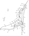
- the closure according to the invention has a bottom part 1 two correspondingly shaped side walls 1 'on which one of two side walls 4' ' and a back part 4 'of existing clamping lever 4 along an articulation axis 5 by means of two Rivets is pivotally articulated, which, as shown in FIG. 3, may have a recess 4 '' ', this bottom part 1 in the direction indicated by the arrow B.
- Transport direction before and / or after the articulation axis 5 has a projection 2 to according to the invention, as shown in Figures 1 and 2, a space between one To produce timing belt 16 and this bottom part 1, and the bottom part 1 has a bore 3rd contains in order to fix it (e.g.
- tension lever 4 can be in its Back part 4 'have a recess 4' '' and is in its closed position by means of locked on both side cheeks 4 '', inwardly directed knobs 6, which in last section of the closing movement of the tensioning lever 4 in curved grooves 6 ' engage, which are formed on both side walls 1 'of the bottom part 1 and on their End holes 6 '' are in which the corresponding knobs 6 when closed Engage the position of the clamping lever 4.
- the tensioning lever 4 contains a two-armed pawl piece 7, which is at a distance from the articulation axis 5 in the tensioning lever 4 between its side cheeks 4 ′′ about a pivot axis 8 is pivoted and acts in a position controlled by a spring 9, which is arranged in a recessed seat on an arm 7 'of the jack piece 7 and acts between this arm and the inner surface of the back part 4 'of the clamping lever 4.
- the Pawl piece 7 is from the position shown in Fig. 2 to one in the back part 4 'of Clamping lever 4 trained stop 10, as can be seen in Fig. 1, to a certain Angle rotatable and can by means of the second arm 7 '' on a steep flank 17 in the Engage toothed belt 16.
- the spring 9 is then advantageously one Coil spring around the articulation axis 8 of the pawl piece 7 and this either with a shortened arm 7 'or one arm.
- a two-armed backstop 11 is arranged on the base part 1 by means of a pin 12, which acts on this bottom part by means of a spring 14, so that on the in the transport direction B located after the pin 12 arm sperm 13, 13 'of the backstop 11 are pressed onto the toothed belt 16, this spring having an axial seat the backstop 11 is arranged and between the backstop 11 and one of the Side walls 1 'of the bottom part 1 acts.
- the belt 16 is in the bottom part 1 between its base and the pawl piece 7 of the Tension lever 4 inserted until the toothed part of the belt 16 in the toothed part 13, 13 'of the backstop 11 engages. If the clamping lever 4 in the direction of arrow A around the Articulation axis 5 pivoted from the closed position to the maximum open position with this movement, which is simultaneously the arm 7 '' in the toothed belt 16 engaging pawl 7 until touching the stop 10 around Articulation axis 8 rotated, the toothed belt 16 transported in the direction of arrow B and thus the pivoting movement of the clamping lever 4 and the pawl piece 7 in a linear translation movement of the toothed belt 16 transformed.
- the tensioning lever 4 can be closed in FIG. 3 seeing recess 4 '' ', which have access to release the backstop 11 without Opening the clamping lever 4 allowed.
- the jack piece 7 with one arm in the direction of the work area and the spring 9 as a spiral spring around the axis 8 be formed, with which the mode of operation according to the invention is again achieved.
- FIG. 1 A better engagement of the arm 7 ′′ in the teeth of the toothed belt 16 is shown in FIG the base part of the lying in the transport direction B before and / or after the tensioning lever Bottom part 1 formed a projection 2, over which the toothed belt 16 slides so that between the bottom part 1 and the belt 16 a space for springing back Cam of the pawl piece by bending the toothed belt 16, as well as to ensure positive engagement of the pawl arm 7 ′′ in the toothed belt 16 is generated, without the belt being damaged when the pawl piece 7 is actuated.
- the spring piece 9 springs back after the end of each tensioning cycle supports or accelerates.
Landscapes
- Health & Medical Sciences (AREA)
- General Health & Medical Sciences (AREA)
- Physical Education & Sports Medicine (AREA)
- Footwear And Its Accessory, Manufacturing Method And Apparatuses (AREA)
- Buckles (AREA)
- Valve Device For Special Equipments (AREA)
- Devices For Conveying Motion By Means Of Endless Flexible Members (AREA)
Claims (13)
- Système de fermeture pour une chaussure, notamment une chaussure de sport, comportant une partie de base (1), au-dessus de laquelle peut être guidée une sangle dentée en dents de scie (16) et sur laquelle un levier de serrage (4) est articulé de manière à pouvoir pivoter, et dans lequel un élément formant cliquet (7) est monté élastiquement dans le levier de serrage (4) de sorte qu'il s'accroche à un flanc pentu (17) de la sangle (16) lors de l'ouverture du levier de serrage (4), pour déplacer cette sangle, et en outre sur la partie de base (1) est articulée, de manière à pouvoir pivoter, un dispositif de blocage anti-retour à deux bras (11), chargé par un ressort et qui s'accroche, par un ergot de blocage (13) prévu sur un bras, à un flanc pentu (17) de la sangle dentée (16), l'ergot de blocage (13) pouvant être dégagé de la sangle dentée (16) à l'encontre de la force (14) d'un ressort, moyennant l'application d'une pression à l'autre bras (15),
caractérisé en ce que
l'élément formant cliquet (7) est monté de manière à pouvoir pivoter à distance de l'axe d'articulation (5) du levier de serrage (4), à l'aide d'un axe de pivotement (8), entre les parois latérales (4'') du levier de serrage (4), et est appliqué au moyen d'un ressort (9) en direction d'une butée (10) contre le levier de serrage (4). - Système de fermeture selon la revendication 1, caractérisé en ce que la butée (10), qui coopère avec l'élément formant cliquet (7), est agencée sous la forme d'un bord de la partie dorsale (4') dans la zone de l'axe d'articulation (5) du levier de serrage (4).
- Système de fermeture selon la revendication 1, caractérisé en ce que l'élément formant cliquet (7) possède un seul bras (7''), qui est destiné à s'engager dans la sangle dentée (16), le ressort (9) étant agencé sous la forme d'un ressort hélicoïdal disposé autour de l'axe de pivotement (8) de l'élément formant cliquet (7).
- Système de fermeture selon la revendication 1 ou 2, caractérisé en ce que l'élément formant cliquet (7) est agencé avec deux bras, l'extrémité d'un bras (7'') étant agencée de manière à s'engager dans la sangle dentée (16), et le ressort (9) est disposé entre la partie dorsale (4') du levier de serrage (4) et l'autre bras (7').
- Système de fermeture selon l'une des revendications 1 à 4, caractérisé en ce que le dispositif de blocage anti-retour (11) est masqué par la partie dorsale (4') et les deux parois latérales (4'') du levier de serrage (4), lorsque ce dernier est dans sa position fermée.
- Système de fermeture selon l'une des revendications 1 à 5, caractérisé en ce que la partie dorsale (4') du levier de serrage (4) possède un évidement (4''') permettant l'accès au bras (15) du dispositif de blocage anti-retour (11), même lorsque le levier de serrage (4) est fermé.
- Système de fermeture selon l'une des revendications 1 à 6, caractérisé en ce que dans la position fermée, le levier de serrage (4) est bloqué contre une ouverture intempestive par au moins un téton (6) qui est formé sur un flasque (4'') et coopère, au moins pendant la dernière partie du déplacement de fermeture, avec une rainure cintrée (6') et, dans la position de fermeture, avec un perçage (6''), dans lequel le téton peut s'encliqueter.
- Système de fermeture selon l'une des revendications 1 à 7, caractérisé en ce que le bras (7') de l'élément formant cliquet (7) est repoussé, lors que le mécanisme est dans la position fermée, à l'encontre de la force (9) du ressort, sur le bras (15) du dispositif de blocage anti-retour (11) de telle sorte que le mécanisme est fermé, dans la position de transport, vis-à-vis de la pénétration de corps étrangers.
- Système de fermeture selon l'une des revendications 1 à 8, caractérisé en ce que le dispositif de blocage anti-retour (11) comporte deux becs de blocage (13, 13'), auxquels sont associées deux dents successives respectives de la sangle dentée (16).
- Système de fermeture selon l'une des revendications 1 à 9, caractérisé en ce que dans la direction de transport est formé, en amont et/ou en aval de l'axe d'articulation (5) du levier de serrage (4), un appendice saillant, au-dessus duquel la sangle dentée (16) glisse de telle sorte que dans la zone d'action de l'élément formant cliquet (7) entre la sangle dentée (16) de la base de l'élément de base (1) est formé un espace intercalaire, qui permet en cet endroit un fléchissement de la sangle dentée (16).
- Système de fermeture selon l'une des revendications 1 à 10, caractérisé en ce que le dispositif de blocage anti-retour (11) est détendu avant sa libération, par le fait que lors de l'ouverture du levier de serrage (4), le bras (7'') de l'élément formant cliquet (7) s'engage, au moyen du ressort (9), dans la sangle dentée (16).
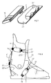
- Système de fermeture selon l'une des revendications 1 à 11, caractérisé en ce que la sangle dentée (16) est reliée à la partie supérieure (23) d'une chaussure par l'intermédiaire d'un ou de plusieurs moyens d'accrochage réglables (18, 18', 19, 19', 20, 20', 21, 21'), associés entre eux.
- Système de fermeture selon la revendications 12, caractérisé en ce qu'au moins un galet à câble rotatif (22) servant à fermer une chaussure est monté sur une extrémité de la sangle dentée, pour coopérer avec des moyens de traction correspondants (22'), de manière à pouvoir tourner en appliquant une surmultiplication ou une démultiplication.
Applications Claiming Priority (2)
| Application Number | Priority Date | Filing Date | Title |
|---|---|---|---|
| AT0112892A AT397337B (de) | 1992-05-29 | 1992-05-29 | Verschluss für einen schuh |
| AT1128/92 | 1992-05-29 |
Publications (2)
| Publication Number | Publication Date |
|---|---|
| EP0572373A1 EP0572373A1 (fr) | 1993-12-01 |
| EP0572373B1 true EP0572373B1 (fr) | 1998-03-11 |
Family
ID=3507194
Family Applications (1)
| Application Number | Title | Priority Date | Filing Date |
|---|---|---|---|
| EP93890109A Expired - Lifetime EP0572373B1 (fr) | 1992-05-29 | 1993-05-25 | Fermeture à courroie dentée |
Country Status (3)
| Country | Link |
|---|---|
| EP (1) | EP0572373B1 (fr) |
| AT (2) | AT397337B (fr) |
| DE (1) | DE59308236D1 (fr) |
Families Citing this family (9)
| Publication number | Priority date | Publication date | Assignee | Title |
|---|---|---|---|---|
| US5416952A (en) * | 1994-01-27 | 1995-05-23 | Burton Snowboards | Ratchet-type buckle |
| ATE210395T1 (de) * | 1996-07-23 | 2001-12-15 | Bauer Italia Spa | Vorrichtung zum klemmen von einer hebelverschlusszahnleiste, insbesondere für eine schliessvorrichtung für sportschuhe |
| US5745959A (en) * | 1997-01-07 | 1998-05-05 | The Burton Corporation | Ratchet-type buckle |
| IT243463Y1 (it) * | 1997-03-17 | 2002-03-04 | Everest Off | Dispositivo di chiusura a leva e cinturino dentato per calzaturesportive in genere. |
| US6374464B1 (en) * | 2000-07-25 | 2002-04-23 | Chin-Kuo Lai | Buckle with fine adjustment means |
| TW588589U (en) * | 2003-01-30 | 2004-05-21 | Taiwan Ind Fastener Corp | Minutely-adjustable slidable buckle |
| ITTV20060227A1 (it) * | 2006-12-21 | 2008-06-22 | Premec Spa | Struttura di leva, particolarmente per calzature sportive. |
| DE102016103595A1 (de) * | 2016-02-24 | 2017-08-24 | Westfalia-Automotive Gmbh | Befestigungsvorrichtung für einen Lastenträger |
| EP3673760A1 (fr) * | 2018-12-27 | 2020-07-01 | Rossignol Lange S.R.L. | Dispositif de verrouillage et déverrouillage pour une chaussure de sport |
Family Cites Families (6)
| Publication number | Priority date | Publication date | Assignee | Title |
|---|---|---|---|---|
| US3662435A (en) * | 1970-08-06 | 1972-05-16 | Allsop I J | Ratcheting buckle for ski boots and the like |
| IT8409513U1 (it) * | 1984-05-08 | 1985-11-08 | Biavaschi Ciapusci Ilde | Ancoraggio di sicurezza ad arpione bloccabile per cinghia dentata di serraggio degli scarponi da sci |
| FR2567374B1 (fr) * | 1984-07-13 | 1986-12-12 | Salomon Sa | Chaussure de ski alpin. |
| CH668167A5 (fr) * | 1986-04-18 | 1988-12-15 | Lange Int Sa | Dispositif de fermeture d'une chaussure. |
| AT389430B (de) * | 1986-06-12 | 1989-12-11 | Riedel Tilo | Spannhebelverschluss, insbesondere fuer skischuhe |
| EP0387402A3 (fr) * | 1989-03-17 | 1990-11-14 | SIDI SPORT S.a.s. di DINO SIGNORI & C. | Dispositif de fermeture pour chaussures de sport, en particulier pour chaussures de motocross, et chaussure munie de ce dispositif |
-
1992
- 1992-05-29 AT AT0112892A patent/AT397337B/de not_active IP Right Cessation
-
1993
- 1993-05-25 EP EP93890109A patent/EP0572373B1/fr not_active Expired - Lifetime
- 1993-05-25 DE DE59308236T patent/DE59308236D1/de not_active Expired - Fee Related
- 1993-05-25 AT AT93890109T patent/ATE163840T1/de not_active IP Right Cessation
Also Published As
| Publication number | Publication date |
|---|---|
| ATE163840T1 (de) | 1998-03-15 |
| EP0572373A1 (fr) | 1993-12-01 |
| AT397337B (de) | 1994-03-25 |
| DE59308236D1 (de) | 1998-04-16 |
| ATA112892A (de) | 1993-08-15 |
Similar Documents
| Publication | Publication Date | Title |
|---|---|---|
| DE2916902C2 (fr) | ||
| EP0083752B1 (fr) | Boucle pour ceintures de sécurité | |
| DE2213972A1 (de) | Klinkenschnalle fuer skistiefel und dergleichen | |
| DE3201319A1 (de) | Skibindungsbacken | |
| DE2821140C2 (de) | Schließe für Riemen, Gurte o.dgl. | |
| DE3344282A1 (de) | Bandmass | |
| DE2629287A1 (de) | Schnallenverschluss fuer skistiefel o.dgl. | |
| DE2806422C3 (fr) | ||
| DE9205067U1 (de) | Verschluß für eine Abschnürvorrichtung für Körperteile | |
| EP0572373B1 (fr) | Fermeture à courroie dentée | |
| DE4427011A1 (de) | Verschluß für Sicherheitsgurte | |
| DE2747626A1 (de) | Skibindung mit einer als fersenbacken oder vorderbacken ausgebildeten skistiefelhalterung | |
| DE102022114415A1 (de) | Messer | |
| CH688023A5 (de) | Bindungseinrichtung zwischen einem Schuh und einem Sportgeraet | |
| EP0130138B1 (fr) | Elément de chaîne à maillons ronds | |
| DE9007718U1 (de) | Karabinerhaken | |
| DE3013953A1 (de) | Schnallenverschluss fuer schuhe, insbesondere fuer ski- oder bergstiefel | |
| AT400680B (de) | Sicherheitsskibindung | |
| DE2231274A1 (de) | Schloss fuer einen sicherheitsgurt | |
| DE4301250C2 (de) | Vorrichtung zum Schließen des Schafts eines Skischuhs | |
| DE60300131T2 (de) | Schliess- und Spannvorrichtung für Sportschuh oder für Bindungssystem für Gleitsportartikel | |
| AT402021B (de) | Skibindung | |
| EP3744208A1 (fr) | Système de fermeture | |
| AT509610B1 (de) | Verstellvorrichtung, insbesondere längenverstellvorrichtung | |
| DE3934877A1 (de) | Bindung zum halten des vorderen endes eines schuhs auf einem langlaufski |
Legal Events
| Date | Code | Title | Description |
|---|---|---|---|
| PUAI | Public reference made under article 153(3) epc to a published international application that has entered the european phase |
Free format text: ORIGINAL CODE: 0009012 |
|
| AK | Designated contracting states |
Kind code of ref document: A1 Designated state(s): AT CH DE FR IT LI SE |
|
| 17P | Request for examination filed |
Effective date: 19940530 |
|
| 17Q | First examination report despatched |
Effective date: 19960628 |
|
| GRAG | Despatch of communication of intention to grant |
Free format text: ORIGINAL CODE: EPIDOS AGRA |
|
| GRAG | Despatch of communication of intention to grant |
Free format text: ORIGINAL CODE: EPIDOS AGRA |
|
| GRAH | Despatch of communication of intention to grant a patent |
Free format text: ORIGINAL CODE: EPIDOS IGRA |
|
| GRAH | Despatch of communication of intention to grant a patent |
Free format text: ORIGINAL CODE: EPIDOS IGRA |
|
| GRAA | (expected) grant |
Free format text: ORIGINAL CODE: 0009210 |
|
| ITF | It: translation for a ep patent filed | ||
| RAP1 | Party data changed (applicant data changed or rights of an application transferred) |
Owner name: AM S.R.L. |
|
| AK | Designated contracting states |
Kind code of ref document: B1 Designated state(s): AT CH DE FR IT LI SE |
|
| REF | Corresponds to: |
Ref document number: 163840 Country of ref document: AT Date of ref document: 19980315 Kind code of ref document: T |
|
| REG | Reference to a national code |
Ref country code: CH Ref legal event code: NV Representative=s name: ISLER & PEDRAZZINI AG Ref country code: CH Ref legal event code: EP |
|
| ET | Fr: translation filed | ||
| REF | Corresponds to: |
Ref document number: 59308236 Country of ref document: DE Date of ref document: 19980416 |
|
| PLBE | No opposition filed within time limit |
Free format text: ORIGINAL CODE: 0009261 |
|
| STAA | Information on the status of an ep patent application or granted ep patent |
Free format text: STATUS: NO OPPOSITION FILED WITHIN TIME LIMIT |
|
| 26N | No opposition filed | ||
| REG | Reference to a national code |
Ref country code: CH Ref legal event code: NV Representative=s name: ABREMA AGENCE BREVETS ET MARQUES GANGUILLET & HUMP |
|
| PGFP | Annual fee paid to national office [announced via postgrant information from national office to epo] |
Ref country code: FR Payment date: 19990518 Year of fee payment: 7 |
|
| PGFP | Annual fee paid to national office [announced via postgrant information from national office to epo] |
Ref country code: CH Payment date: 19990601 Year of fee payment: 7 |
|
| PGFP | Annual fee paid to national office [announced via postgrant information from national office to epo] |
Ref country code: AT Payment date: 19990630 Year of fee payment: 7 |
|
| PGFP | Annual fee paid to national office [announced via postgrant information from national office to epo] |
Ref country code: DE Payment date: 19991221 Year of fee payment: 7 |
|
| PG25 | Lapsed in a contracting state [announced via postgrant information from national office to epo] |
Ref country code: AT Free format text: LAPSE BECAUSE OF NON-PAYMENT OF DUE FEES Effective date: 20000525 |
|
| PGFP | Annual fee paid to national office [announced via postgrant information from national office to epo] |
Ref country code: SE Payment date: 20000526 Year of fee payment: 8 |
|
| PG25 | Lapsed in a contracting state [announced via postgrant information from national office to epo] |
Ref country code: LI Free format text: LAPSE BECAUSE OF NON-PAYMENT OF DUE FEES Effective date: 20000531 Ref country code: CH Free format text: LAPSE BECAUSE OF NON-PAYMENT OF DUE FEES Effective date: 20000531 |
|
| REG | Reference to a national code |
Ref country code: CH Ref legal event code: PL |
|
| PG25 | Lapsed in a contracting state [announced via postgrant information from national office to epo] |
Ref country code: FR Free format text: LAPSE BECAUSE OF NON-PAYMENT OF DUE FEES Effective date: 20010131 |
|
| PG25 | Lapsed in a contracting state [announced via postgrant information from national office to epo] |
Ref country code: DE Free format text: LAPSE BECAUSE OF NON-PAYMENT OF DUE FEES Effective date: 20010301 |
|
| REG | Reference to a national code |
Ref country code: FR Ref legal event code: ST |
|
| PG25 | Lapsed in a contracting state [announced via postgrant information from national office to epo] |
Ref country code: SE Free format text: LAPSE BECAUSE OF NON-PAYMENT OF DUE FEES Effective date: 20010526 |
|
| PG25 | Lapsed in a contracting state [announced via postgrant information from national office to epo] |
Ref country code: IT Free format text: LAPSE BECAUSE OF NON-PAYMENT OF DUE FEES;WARNING: LAPSES OF ITALIAN PATENTS WITH EFFECTIVE DATE BEFORE 2007 MAY HAVE OCCURRED AT ANY TIME BEFORE 2007. THE CORRECT EFFECTIVE DATE MAY BE DIFFERENT FROM THE ONE RECORDED. Effective date: 20050525 |