EP0572373B1 - Toothed buckle fastening - Google Patents
Toothed buckle fastening Download PDFInfo
- Publication number
- EP0572373B1 EP0572373B1 EP93890109A EP93890109A EP0572373B1 EP 0572373 B1 EP0572373 B1 EP 0572373B1 EP 93890109 A EP93890109 A EP 93890109A EP 93890109 A EP93890109 A EP 93890109A EP 0572373 B1 EP0572373 B1 EP 0572373B1
- Authority
- EP
- European Patent Office
- Prior art keywords
- arm
- tension lever
- closure according
- toothed
- spring
- Prior art date
- Legal status (The legal status is an assumption and is not a legal conclusion. Google has not performed a legal analysis and makes no representation as to the accuracy of the status listed.)
- Expired - Lifetime
Links
- 238000005452 bending Methods 0.000 claims description 2
- 230000035515 penetration Effects 0.000 claims description 2
- 206010053648 Vascular occlusion Diseases 0.000 description 3
- 239000002184 metal Substances 0.000 description 2
- 238000010276 construction Methods 0.000 description 1
- 230000001419 dependent effect Effects 0.000 description 1
- 238000006073 displacement reaction Methods 0.000 description 1
- 230000007257 malfunction Effects 0.000 description 1
- 210000001331 nose Anatomy 0.000 description 1
- 238000000926 separation method Methods 0.000 description 1
Images


Classifications
-
- A—HUMAN NECESSITIES
- A43—FOOTWEAR
- A43C—FASTENINGS OR ATTACHMENTS OF FOOTWEAR; LACES IN GENERAL
- A43C11/00—Other fastenings specially adapted for shoes
- A43C11/14—Clamp fastenings, e.g. strap fastenings; Clamp-buckle fastenings; Fastenings with toggle levers
- A43C11/1406—Fastenings with toggle levers; Equipment therefor
- A43C11/142—Fastenings with toggle levers with adjustment means provided for on the shoe, e.g. rack
-
- A—HUMAN NECESSITIES
- A43—FOOTWEAR
- A43B—CHARACTERISTIC FEATURES OF FOOTWEAR; PARTS OF FOOTWEAR
- A43B5/00—Footwear for sporting purposes
- A43B5/04—Ski or like boots
- A43B5/0427—Ski or like boots characterised by type or construction details
- A43B5/0452—Adjustment of the forward inclination of the boot leg
- A43B5/0454—Adjustment of the forward inclination of the boot leg including flex control; Dampening means
- A43B5/0456—Adjustment of the forward inclination of the boot leg including flex control; Dampening means with the actuator being disposed at the rear side of the boot
-
- A—HUMAN NECESSITIES
- A43—FOOTWEAR
- A43C—FASTENINGS OR ATTACHMENTS OF FOOTWEAR; LACES IN GENERAL
- A43C11/00—Other fastenings specially adapted for shoes
- A43C11/14—Clamp fastenings, e.g. strap fastenings; Clamp-buckle fastenings; Fastenings with toggle levers
- A43C11/1406—Fastenings with toggle levers; Equipment therefor
- A43C11/146—Fastenings with toggle levers with adjustment means provided for on the strap, e.g. ratchet strap
Definitions
- the invention relates to a closure for a shoe, in particular a Sports shoe with a bottom part over which a sawtooth-like toothed belt can be guided and on which a clamping lever is pivotally articulated, a in the clamping lever Pawl piece is resiliently mounted so that it opens on a steep when opening the clamping lever Flank of the belt engages to transport it, and also on the bottom part Spring-loaded, two-armed backstop is pivotally articulated with one on one Arm provided locking lug attacks on a steep flank of the toothed belt, being by Pushing the other arm against the locking lug against spring force out of engagement with the toothed belt is feasible
- the object of the invention is a safe and easy closing and / or opening the Shoes under various external influences, such as wetness, low temperatures or To ensure dirt.
- the shoe usually for the purpose of sports
- a toothed belt fastener according to the prior art is in EP-A1-400213 (SIDI) disclosed, wherein in the tensioning lever of the mechanism is displaceable by spring force, with the Row of teeth can be brought into engagement part which is elastically in by the clamping lever Is pushed towards the timing belt.
- US-A-3 662435 (ALLSOP) describes in detail a similar locking mechanism, the one manually movable one-piece clamping lever or a clamping lever has that of a lever piece, a holding arm and an operation piece to one pivotable engagement or non-engagement is formed in the toothed belt.
- the holding arm is arranged spring-loaded in the direction of the toothed belt and pivotally mounted on the tensioning lever.
- this closure has a generic character a one-armed lever, by means of which the toothed belt when closing the tensioning lever is transported. In practice, this closure variant has therefore not proven itself.
- a toothed belt lock has become known from EP-B1-259896 (Raichle), which contains a band-shaped holding element guided around a ski boot, at the end of the latter Notches are arranged, the closure part by a pivotable clamping lever, in which a slide engaging in the row of teeth is guided, which during the backward movement the clamping lever is returned to its rest position by spring force, and by a releasable backstop is formed.
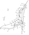
- the closure according to the invention has a bottom part 1 two correspondingly shaped side walls 1 'on which one of two side walls 4' ' and a back part 4 'of existing clamping lever 4 along an articulation axis 5 by means of two Rivets is pivotally articulated, which, as shown in FIG. 3, may have a recess 4 '' ', this bottom part 1 in the direction indicated by the arrow B.
- Transport direction before and / or after the articulation axis 5 has a projection 2 to according to the invention, as shown in Figures 1 and 2, a space between one To produce timing belt 16 and this bottom part 1, and the bottom part 1 has a bore 3rd contains in order to fix it (e.g.
- tension lever 4 can be in its Back part 4 'have a recess 4' '' and is in its closed position by means of locked on both side cheeks 4 '', inwardly directed knobs 6, which in last section of the closing movement of the tensioning lever 4 in curved grooves 6 ' engage, which are formed on both side walls 1 'of the bottom part 1 and on their End holes 6 '' are in which the corresponding knobs 6 when closed Engage the position of the clamping lever 4.
- the tensioning lever 4 contains a two-armed pawl piece 7, which is at a distance from the articulation axis 5 in the tensioning lever 4 between its side cheeks 4 ′′ about a pivot axis 8 is pivoted and acts in a position controlled by a spring 9, which is arranged in a recessed seat on an arm 7 'of the jack piece 7 and acts between this arm and the inner surface of the back part 4 'of the clamping lever 4.
- the Pawl piece 7 is from the position shown in Fig. 2 to one in the back part 4 'of Clamping lever 4 trained stop 10, as can be seen in Fig. 1, to a certain Angle rotatable and can by means of the second arm 7 '' on a steep flank 17 in the Engage toothed belt 16.
- the spring 9 is then advantageously one Coil spring around the articulation axis 8 of the pawl piece 7 and this either with a shortened arm 7 'or one arm.
- a two-armed backstop 11 is arranged on the base part 1 by means of a pin 12, which acts on this bottom part by means of a spring 14, so that on the in the transport direction B located after the pin 12 arm sperm 13, 13 'of the backstop 11 are pressed onto the toothed belt 16, this spring having an axial seat the backstop 11 is arranged and between the backstop 11 and one of the Side walls 1 'of the bottom part 1 acts.
- the belt 16 is in the bottom part 1 between its base and the pawl piece 7 of the Tension lever 4 inserted until the toothed part of the belt 16 in the toothed part 13, 13 'of the backstop 11 engages. If the clamping lever 4 in the direction of arrow A around the Articulation axis 5 pivoted from the closed position to the maximum open position with this movement, which is simultaneously the arm 7 '' in the toothed belt 16 engaging pawl 7 until touching the stop 10 around Articulation axis 8 rotated, the toothed belt 16 transported in the direction of arrow B and thus the pivoting movement of the clamping lever 4 and the pawl piece 7 in a linear translation movement of the toothed belt 16 transformed.
- the tensioning lever 4 can be closed in FIG. 3 seeing recess 4 '' ', which have access to release the backstop 11 without Opening the clamping lever 4 allowed.
- the jack piece 7 with one arm in the direction of the work area and the spring 9 as a spiral spring around the axis 8 be formed, with which the mode of operation according to the invention is again achieved.
- FIG. 1 A better engagement of the arm 7 ′′ in the teeth of the toothed belt 16 is shown in FIG the base part of the lying in the transport direction B before and / or after the tensioning lever Bottom part 1 formed a projection 2, over which the toothed belt 16 slides so that between the bottom part 1 and the belt 16 a space for springing back Cam of the pawl piece by bending the toothed belt 16, as well as to ensure positive engagement of the pawl arm 7 ′′ in the toothed belt 16 is generated, without the belt being damaged when the pawl piece 7 is actuated.
- the spring piece 9 springs back after the end of each tensioning cycle supports or accelerates.
Landscapes
- Health & Medical Sciences (AREA)
- General Health & Medical Sciences (AREA)
- Physical Education & Sports Medicine (AREA)
- Footwear And Its Accessory, Manufacturing Method And Apparatuses (AREA)
- Buckles (AREA)
- Valve Device For Special Equipments (AREA)
- Devices For Conveying Motion By Means Of Endless Flexible Members (AREA)
Abstract
Description
Die Erfindung bezieht sich auf einen Verschluß für einen Schuh, insbesondere einem Sportschuh, mit einem Bodenteil, über den ein sägezahnartiger Zahnriemen führbar ist und an welchem ein Spannhebel schwenkbar angelenkt ist, wobei in dem Spannhebel ein Klinkenstück federnd so gelagert ist, daß es beim Öffnen des Spannhebels an einer steilen Flanke des Riemens angreift, um diesen zu transportieren, und an dem Bodenteil ferner eine federbelastete, zweiarmige Rücklaufsperre schwenkbar angelenkt ist, die mit einer an einem Arm vorgesehenen Sperrnase an einer steilen Flanke des Zahnriemens angreift, wobei durch Druck auf den anderen Arm die Sperrnase gegen Federkraft außer Eingriff mit dem Zahnriemen bringbar istThe invention relates to a closure for a shoe, in particular a Sports shoe with a bottom part over which a sawtooth-like toothed belt can be guided and on which a clamping lever is pivotally articulated, a in the clamping lever Pawl piece is resiliently mounted so that it opens on a steep when opening the clamping lever Flank of the belt engages to transport it, and also on the bottom part Spring-loaded, two-armed backstop is pivotally articulated with one on one Arm provided locking lug attacks on a steep flank of the toothed belt, being by Pushing the other arm against the locking lug against spring force out of engagement with the toothed belt is feasible
Aufgabe der Erfindung ist es, ein sicheres und leichtes Verschließen und/oder Öffnen des Schuhs unter verschiedensten äußeren Einflüssen, wie Nässe, niedrige Temperaturen oder Schmutz zu gewährleisten. Zusätzlich soll der Schuh (meist zum Zweck der Sportausübung) sehr fest verschlossen werden. Dies führt zu großen Spannungen am Verschlußteil und hat bei bekannten Ausführungsformen ein Nichtfunktionieren und häufig eine Beschädigung desselben und/oder des Zahnriemens zur Folge.The object of the invention is a safe and easy closing and / or opening the Shoes under various external influences, such as wetness, low temperatures or To ensure dirt. In addition, the shoe (usually for the purpose of sports) to be closed very tightly. This leads to great tension on the closure part and has known embodiments a malfunction and often damage the same and / or the timing belt.
Ein Zahnriemenverschluß nach dem Stand der Technik ist in der EP-A1-400213 (SIDI) geoffenbart, wobei im Spannhebel des Mechanismus ein durch Federkraft verschiebbarer, mit der Zahnreihe in Eingriff bringbarer Teil angeordnet ist, der von dem Spannhebel elastisch in Richtung Zahnriemen gedrängt wird.A toothed belt fastener according to the prior art is in EP-A1-400213 (SIDI) disclosed, wherein in the tensioning lever of the mechanism is displaceable by spring force, with the Row of teeth can be brought into engagement part which is elastically in by the clamping lever Is pushed towards the timing belt.
Eine weitere Ausführungsform eines solchen Verschlusses ist in der EP-A2-387402 geoffenbart, wobei der Zahnriemen mindestens zwei Zahnreihen aufweist, von denen eine hauptsächlich zur Spannung des Riemens (Verschließen des Schuhs) und die weiteren mit dem Bremsmittel (zum Öffnen des Verschlusses) zusammenwirken. Bei beiden Ausführungsformen weist der Spannhebel in seinem Arbeitsbereich einen verschiebbaren Teil auf, der die formschlüssige Verbindung mit der Verzahnung des Zahnriemens darstellt.Another embodiment of such a closure is in EP-A2-387402 revealed, wherein the toothed belt has at least two rows of teeth, one of which is mainly for tensioning the strap (closing the shoe) and the others with the Interact brake means (to open the lock). In both embodiments the clamping lever has a displaceable part in its working area, which the represents positive connection with the toothing of the toothed belt.
Die US-A-3 662435 (ALLSOP) beschreibt in ausführlicher Weise einen ähnlichen Verschließmechanismus, der einen manuell bewegbaren einstückigen Spannhebel oder einen Spannhebel aufweist, der aus einem Hebelstück, einem Haltearm und einem Operationsstück zu einem schwenkbaren Eingreifen bzw. Nichteingreifen in den Zahnriemen ausgebildet ist. Bei der letzteren Ausführungsform ist der Haltearm in Richtung Zahnriemen federbelastet angeordnet und an dem Spannhebel schwenkbar gelagert. Gattungsgemäß weist dieser Verschluß jedoch einen einarmigen Hebel auf, mittels welchem der Zahnriemen beim Schließen des Spannhebels transportiert wird. In der Praxis hat sich diese Verschlußvariante daher nicht bewährt.US-A-3 662435 (ALLSOP) describes in detail a similar locking mechanism, the one manually movable one-piece clamping lever or a clamping lever has that of a lever piece, a holding arm and an operation piece to one pivotable engagement or non-engagement is formed in the toothed belt. In the the latter embodiment, the holding arm is arranged spring-loaded in the direction of the toothed belt and pivotally mounted on the tensioning lever. However, this closure has a generic character a one-armed lever, by means of which the toothed belt when closing the tensioning lever is transported. In practice, this closure variant has therefore not proven itself.
Weiters ist durch die EP-B1-259896 (Raichle) ein Zahnriemenverschluß bekannt geworden, der ein bandförmiges, um einen Schischuh geführtes Halteelement enthält, an dessen Ende Rastkerben angeordnet sind, wobei der Verschlußteil durch einen schwenkbaren Spannhebel, in dem ein in die Zahnreihe eingreifender Schieber geführt ist, der bei der Rückwartsbewegung des Spannhebels durch Federkraft in seine Ruhelage zurückgebracht wird, und durch eine lösbare Rücklaufsperre gebildet wird.Furthermore, a toothed belt lock has become known from EP-B1-259896 (Raichle), which contains a band-shaped holding element guided around a ski boot, at the end of the latter Notches are arranged, the closure part by a pivotable clamping lever, in which a slide engaging in the row of teeth is guided, which during the backward movement the clamping lever is returned to its rest position by spring force, and by a releasable backstop is formed.
Aufgabe der Erfindung ist es, Nachteile bekannter Vorrichtungen zu beseitigen und einen für
vielseitige Verwendungszwecke einsetzbaren, trotzdem mechanisch einfach ausgebildeten
Verschluß zu entwickeln. Die Erfindung samt weiterer, zum Teil in den abhangigen
Unteransprüchen geoffenbarter Vorteile wird im folgenden an Hand beispielsweiser
Ausführungsformen naher erläutert, die in den beiliegenden Figuren veranschaulicht sind. In
diesen zeigen:
Gemäß Fig. 1 bis 3 weist der Verschuß entsprechend der Erfindung einen Bodenteil 1 mit
zwei entsprechend geformten Seitenwänden 1' auf, an denen ein aus zwei Seitenwangen 4''
und einem Rückenteil 4' bestehender Spannhebel 4 entlang einer Anlenkachse 5 mittels zweier
Nieten schwenkbar angelenkt ist, der wie in Fig. 3 gezeigt gegebenenfalls eine Ausnehmung
4''' aufweisen kann, wobei dieser Bodenteil 1 in der durch den Pfeil B angegebenen
Transportrichtung vor und/oder nach der Anlenkachse 5 einen Vorsprung 2 aufweist, um
erfindungsgemäß, wie in Figur 1 und 2 dargestellt ist, einen Zwischenraum zwischen einem
Zahnriemen 16 und diesem Bodenteil 1 herzustellen, und der Bodenteil 1 eine Bohrung 3
enthält, um diesen (z. B. mittels einer Niete) am Schuhoberteil 23 zu befestigen. Der
Spannhebel 4 kann in einer weiteren Ausführungsform, die in Fig. 3 gezeigt wird, in seinem
Rückenteil 4' eine Ausnehmung 4''' aufweisen und ist in seiner geschlossenen Stellung mittels
an beiden Seitenwangen 4'' ausgebildeten, einwärts gerichteten Noppen 6 verriegelt, die im
letzten Teilabschnitt der Schließbewegung des Spannhebels 4 in gekrümmte Rinnen 6'
eingreifen, welche an beiden Seitenwänden 1' des Bodenteils 1 ausgebildet sind und an deren
Ende sich Bohrungen 6'' befinden, in denen die entsprechenden Noppen 6 bei geschlossener
Stellung des Spannhebels 4 einrasten.1 to 3, the closure according to the invention has a
Der Spannhebel 4 enthält ein zweiarmiges Klinkenstück 7, das im Abstand von der Anlenkachse
5 in dem Spannhebel 4 zwischen dessen Seitenwangen 4'' um eine Schwenkachse 8
drehbar angelenkt ist und in einer Stellung wirkt, die von einer Feder 9 gesteuert wird, welche
in einem ausgesparten Sitz auf einem Arm 7' des Klinkenstückes 7 angeordnet ist und
zwischen diesem Arm und der Innenfläche des Rückenteils 4' des Spannhebels 4 wirkt. Das
Klinkenstück 7 ist von der in Fig. 2 gezeigten Lage bis zu einem im Rückenteil 4' des
Spannhebels 4 ausgebildeten Anschlag 10, wie in Fig. 1 zu sehen ist, um einen bestimmten
Winkel verdrehbar und kann mittels des zweiten Armes 7'' an einer steilen Flanke 17 in den
Zahnriemen 16 eingreifen. Im Fall einer weiteren Ausführungsform, die in Fig. 3 dargestellt
ist und bei welcher der Rückenteil 4' des Spannhebels 4 im Bereich der Feder 9
erfindungsgemäß eine Ausnehmung 4''' aufweist, ist die Feder 9 dann vorteilhafterweise eine
Schraubenfeder um die Anlenkachse 8 des Klinkenstückes 7 und dieses entweder mit einem
verkürzten Arm 7' oder einarmig ausgebildet.The
An dem Bodenteil 1 ist mittels eines Stiftes 12 eine zweiarmige Rücklaufsperre 11 angeordnet,
die an diesem Bodenteil mittels einer Feder 14 wirkt, sodaß die auf dem in Transportrichtung
B nach dem Stift 12 gelegenen Arm befindlichen Spermasen 13, 13' der Rücklaufsperre
11 auf den Zahnriemen 16 gedrückt werden, wobei diese Feder an einem axialen Sitz
der Rücklaufsperre 11 angeordnet ist und zwischen der Rücklaufsperre 11 und einer der
Seitenwände 1' des Bodenteils 1 wirkt. Durch Drücken an dem zweiten Arm 15 gegen die
Federkraft 14 der Rücklaufsperre werden die Spermasen 13, 13' von den entsprechenden
Zähnen des Zahnriemens 16 getrennt.A two-
Durch den Bodenteil 1, zwischen seiner Basis und der Rücklaufsperre 11, sowie zwischen den
beiden Seitenwangen 4'' des Spannhebels 1, ist ein Zahnriemen 16 hindurchgeführt, dessen
Zähne je eine steile 17 und eine flache 17' Flanke aufweisen, wobei dieser Zahnriemen 16 an
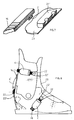
seinem in Richtung Schuhoberteil 23 gelegenen Ende, wie in Fig. 4 bis 8 gezeigt,
unterschiedliche,m einander zugeordnete Einhakmittel 18, 18', 19, 19', 20, 20' 21, 21' 22, 22'
aufweisen kann und seine Transportrichtung beim Verschließen des Schuhes in Figuren 1 und
2 durch den Pfeil B angedeutet ist.Through the
Die Wirkungsweise des erfindungsgemäßen Zahnriemenverschlusses wird im weiteren unter Bezugnahme auf die Fig. 1 bis 3 näher erläutert.The mode of operation of the toothed belt closure according to the invention is described below 1 to 3 explained in more detail.
Der Riemen 16 wird in den Bodenteil 1 zwischen seiner Basis und dem Klinkenstück 7 des
Spannhebels 4 eingeführt, bis der verzahnten Teil des Riemens 16 in den verzahnten Teil 13,
13' der Rücklaufsperre 11 eingreift. Wenn der Spannhebel 4 in Richtung des Pfeiles A um die
Anlenkachse 5 von der geschlossenen Stellung bis zur maximalen Öffnungsstellung geschwenkt
wird, wird mit dieser Bewegung, bei der sich gleichzeitig das mit dem Arm 7'' in
den Zahnriemen 16 eingreifende Klinkenstück 7 bis zum Berühren des Anschlages 10 um die
Anlenkachse 8 verdreht, der Zahnriemen 16 in Richtung des Pfeiles B transportiert und somit
die Schwenkbewegung des Spannhebels 4 und des Klinkenstückes 7 in eine lineare Translationsbewegung
des Zahnriemens 16 verwandelt. Die auf diese Linearbewegung des Riemens
übertragene Kraft überwindet den Widerstand der Feder 14 der Rücklaufsperre 11, sodaß das
Hindurchführen des Zahnriemens 16 mit sukzessivem Einrasten des verzahnten Teils 13, 13'
der Rücklaufsperre 11 in aufeinanderfolgenden verzahnten Teilstücken des Riemens 16 ermöglicht
wird.The
Solche Schwenkbewegungen des Spannhebels 4 werden ausgeführt, bis der Schuh fest verschlossen
ist, wobei durch die erfindungsgemäße Konstruktion gewahrleistet wird, daß bei
der Verschiebebewegung des Riemens 16 mindestens ein Zahn je Öffnen und Schließen des
Spannhebels 4 überwunden wird. Nach dem gewünschten Verschließen bringt man den
Spannhebel 4 in seine vollständig geschlossene Stellung, in der einander zugeordnete
Einrastmittel 6, 6', 6'' ein versehentliches Öffnen des Spannhebels 4 verhindern und der
Spannhebel 4 in dieser Stellung den Mechanismus gegen Eindringen von Fremdkörpern
abdeckt. In einer weiteren, hier nicht gezeigten Ausführungsform, kann der Spannhebel 4
zusätzlich mittels einer in Transportrichtung B hinter dem Verschluß liegenden Klammer, die
in Längsrichtung bewegbar am Zahnriemen 16 oder fest am Bodenteil 1 angebracht ist,
zusätzlich gegen versehentliches Öffnen gesichert werden.Such pivoting movements of the
Bei der Schließbewegung des Spannhebels 4, drückt das Klinkenstück 7, auf dessen Arm 7'
sich die Feder 9 befindet, mit diesem Arm auf die Rücklaufsperre 11 und überwindet den
Widerstand der Feder 9, sodaß, wie in Fig. 2 zu sehen ist, eine Verdrehung des Klinkenstückes
7 um einen bestimmten Winkel bewirkt wird. Diese Drehung ermöglicht es, bei geschlossenem
Hebel 4, eine bemerkenswerte Reduktion der sich zwischen dem Klinkenstück 7
und dem verzahnten Teil des Riemens 16 in Richtung des Pfeiles B bildenden Öffnung des
Mechanismus zu erzielen. Das bringt den großen Vorteil mit sich, daß die Wahrscheinlichkeit
des Eindringens von Fremdkörpern in den Verschließmechanismus erheblich reduziert wird.During the closing movement of the
Zum Nachlassen oder Öffnen des Verschlusses öffnet man den Spannhebel 4 und drückt den
Arm 15 der Rücklaufsperre 11 in Richtung Basis des Bodenteils 1, wodurch die eingerasteten
Nasen 13, 13' der Sperre 11 von den in der Nähe der Rücklaufsperre liegenden Zähnen des
Zahnriemens 16 getrennt werden. Durch das Öffnen des Spannhebels 4 wird der Spannmechanismus
etwas aktiviert, das heißt, durch ein Eingreifen des Klinkenstückes 7 in den
Zahnriemen 16 wird eine teilweise Entlastung der Rücklaufsperre 11 erzielt und somit der
Trennvorgang der korrespondierenden Verzahnungen erleichtert. Dies bedeutet vor allem in
Hinblick darauf, daß der Verschluß vielseitig und unter verschiedensten äußeren Bedingungen,
wie z.B. Schnee, Schmutz, Nässe, Kälte eingesetzt wird, einen erheblichen Vorteil,
denn dadurch wird eine unter solchen Bedingungen leicht mögliche Beschädigung der
entsprechenden Verzahnungen vermieden, wodurch dem Verschluß eine lange Lebensdauer
garantiert wird. In einer anderen Ausführungsform kann der Spannhebel 4 eine in Fig. 3 zu
sehende Ausnehmung 4''' aufweisen, die den Zugang zum Lösen der Rücklaufsperre 11 ohne
Öffnen des Spannhebels 4 gestattet. Bei einer solchen Ausführungsform kann das Klinkenstück
7 einarmig in Richtung Arbeitsbereich und die Feder 9 als Spiralfeder um die Achse 8
ausgebildet sein, womit wieder die erfindungsgemäße Wirkungsweise erreicht wird.To release or open the lock, open the
Um ein Zurückspringen des in den Zahnriemen 16 eingreifenden Klinkenstückes 7 nach jeder
Schwenkbewegung des Spannhebels 4 in seine ursprüngliche Lage vor dem Spannzyklus und
einen besseren Eingriff des Armes 7'' in die Zähne des Zahnriemens 16 zu ermöglichen, ist in
dem in Transportrichtung B vor und/oder nach dem Spannhebel liegenden Basisteil des
Bodenteils 1 ein Vorsprung 2 ausgebildet, über den der Zahnriemen 16 so gleitet, daß
zwischen dem Bodenteil 1 und dem Riemen 16 ein Zwischenraum zum Zurückspringen der
Nocke des Klinkenstückes durch Biegung des Zahnriemens 16, sowie zum Gewährleisten
eines formschlüssigen Eingriffs des Klinkenstückarmes 7'' in den Zahnriemen 16 erzeugt wird,
ohne daß der Riemen beim Betätigen des Klinkenstückes 7 beschädigt wird. Das
Zurückspringen des Klinkenstückes nach dem Ende jedes Spannzyklus wird durch die Feder 9
unterstützt bzw. beschleunigt. Durch diese erfindungsgemäße Wirkungsweise wird eine
möglichst lange Eingreifstrecke des Klinkenstückes in den Zahnriemen und somit ein
maximaler Transportweg je Spannzyklus ermöglicht.In order for the
Der Zahnriemen 16 kann beispielsweise folgendermaßen mit dem Schuhwerk verbunden sein:
Claims (13)
- Closure for a shoe, in particular a sport shoe, having a base part (1), over which a saw-toothed toothed strap can be guided and on which a tension lever (4) is pivotably hinged, wherein a ratchet piece (7) is mounted in the tension lever (4) resiliently so that when opening the tension layer (4) it engages on a steep flank (17) of the strap (16) in order to feed the latter, and on the base part (1) is also pivotably hinged a spring-loaded, double-armed back stop (11) which engages on a steep flank (17) of the toothed strap (16) using a locking notch (13) provided on one arm, wherein the locking notch (13) can be disengaged against spring force (14) from the toothed strap (16) by means of pressure on the other arm (15), characterised in that the ratchet piece (7) is pivotably mounted at a distance from the hinge axle (5) of the tension lever (4) by means of a pivoting axle (8) between the side walls (4'') of the tension lever (4) and stressed by means of a spring (9) in the direction of a stop (10) on the tension lever (4).
- Closure according to claim 1, characterised in that the stop (10) cooperating with the ratchet piece (7) is designed as an edge of the back part (4') in the region of the hinge axle (5) of the tension lever (4).
- Closure according to claim 1, characterised in that the ratchet piece (7) has a single arm (7'') which is provided for engagement in the toothed strap (16), wherein the spring (9) is designed as a spiral spring about the pivoting axle (8) of the ratchet piece (7).
- Closure according to claim 1 or 2, characterised in that the ratchet piece (7) is designed to have two arms, wherein the end of one arm (7'') is designed for engagement in the toothed strap (16) and the spring (9) is arranged between the back part (4') of the tension lever (4) and the other arm (7').
- Closure according to one of claims 1 to 4, characterised in that the back stop (11) is covered by the back part (4') and the two side parts (4'') of the tension lever (4) in its closed position.
- Closure according to one of claims 1 to 5, characterised in that the back part (4') of the tension lever (4) has a recess (4''') in order to facilitate the access to the arm (15) of the back stop (11) even when the tension lever (4) is closed.
- Closure according to one of claims 1 to 6, characterised in that the tension lever (4) in the closed position is secured against inadvertent opening by at least one burl (6) formed on an end piece (4'') and which cooperates at least during the final part of the closing movement with a curved groove (6') and in the closing position with a bore (6'') into which the burl can lock.
- Closure according to one of claims 1 to 7, characterised in that the arm (7') of the ratchet piece (7) in the closed position of the mechanism is pressed against spring force (9) on the arm (15) of the back stop (11) so that the mechanism is sealed against penetration of foreign bodies in the feed direction.
- Closure according to one of claims 1 to 8, characterised in that the back stop (11) has two locking notches (13, 13') to which are assigned in each case two sequential teeth of the toothed strap (16).
- Closure according to one of claims 1 to 9, characterised in that in the feed direction before and/or after the hinge axle (5) of the tension lever (4), a projection is formed, over which the toothed strap (16) glides so that in the effective range of the ratchet piece (7) between the toothed strap (16) and the bottom of the base part (1), a gap is formed which facilitates bending of the toothed strap (16) there.
- Closure according to one of claims 1 to 10, characterised in that the back stop (11) is relieved before its release, in that when opening the tension lever (4) the arm (7'') of the ratchet piece (7) engages in the toothed strap (16) by means of the spring (9).
- Closure according to one of claims 1 to 11, characterised in that the toothed strap (16) is connected to the upper part (23) of a shoe by one or more adjustable hooking means (18, 18', 19, 19', 20, 20', 21, 21') assigned to one another.
- Closure according to claim 12, characterised in that at least one rotatable rope pulley (22) for closing a shoe by means of gearing up or down is rotatably mounted on the toothed strap for cooperation with corresponding drawing means (22') on one end.
Applications Claiming Priority (2)
| Application Number | Priority Date | Filing Date | Title |
|---|---|---|---|
| AT0112892A AT397337B (en) | 1992-05-29 | 1992-05-29 | CLOSURE FOR A SHOE |
| AT1128/92 | 1992-05-29 |
Publications (2)
| Publication Number | Publication Date |
|---|---|
| EP0572373A1 EP0572373A1 (en) | 1993-12-01 |
| EP0572373B1 true EP0572373B1 (en) | 1998-03-11 |
Family
ID=3507194
Family Applications (1)
| Application Number | Title | Priority Date | Filing Date |
|---|---|---|---|
| EP93890109A Expired - Lifetime EP0572373B1 (en) | 1992-05-29 | 1993-05-25 | Toothed buckle fastening |
Country Status (3)
| Country | Link |
|---|---|
| EP (1) | EP0572373B1 (en) |
| AT (2) | AT397337B (en) |
| DE (1) | DE59308236D1 (en) |
Families Citing this family (9)
| Publication number | Priority date | Publication date | Assignee | Title |
|---|---|---|---|---|
| US5416952A (en) * | 1994-01-27 | 1995-05-23 | Burton Snowboards | Ratchet-type buckle |
| ATE210395T1 (en) * | 1996-07-23 | 2001-12-15 | Bauer Italia Spa | DEVICE FOR CLAMPING A LEVER LOCKING BAR, IN PARTICULAR FOR A CLOSING DEVICE FOR SPORTS SHOES |
| US5745959A (en) * | 1997-01-07 | 1998-05-05 | The Burton Corporation | Ratchet-type buckle |
| IT243463Y1 (en) * | 1997-03-17 | 2002-03-04 | Everest Off | LEVER CLOSING DEVICE AND TOOTHED STRAP FOR SPORTY SHOES IN GENERAL. |
| US6374464B1 (en) * | 2000-07-25 | 2002-04-23 | Chin-Kuo Lai | Buckle with fine adjustment means |
| TW588589U (en) * | 2003-01-30 | 2004-05-21 | Taiwan Ind Fastener Corp | Minutely-adjustable slidable buckle |
| ITTV20060227A1 (en) * | 2006-12-21 | 2008-06-22 | Premec Spa | LEVER STRUCTURE, PARTICULARLY FOR SPORTS SHOES. |
| DE102016103595A1 (en) * | 2016-02-24 | 2017-08-24 | Westfalia-Automotive Gmbh | Fastening device for a load carrier |
| EP3673760A1 (en) * | 2018-12-27 | 2020-07-01 | Rossignol Lange S.R.L. | Device for fastening and unfastening a sports shoe |
Family Cites Families (6)
| Publication number | Priority date | Publication date | Assignee | Title |
|---|---|---|---|---|
| US3662435A (en) * | 1970-08-06 | 1972-05-16 | Allsop I J | Ratcheting buckle for ski boots and the like |
| IT8409513U1 (en) * | 1984-05-08 | 1985-11-08 | Biavaschi Ciapusci Ilde | Lockable harpoon safety anchor for ski boot tightening toothed strap |
| FR2567374B1 (en) * | 1984-07-13 | 1986-12-12 | Salomon Sa | ALPINE SKI SHOE. |
| CH668167A5 (en) * | 1986-04-18 | 1988-12-15 | Lange Int Sa | Fastener with toothed strap sliding in stirrup |
| AT389430B (en) * | 1986-06-12 | 1989-12-11 | Riedel Tilo | Tension lever closure, in particular for ski boots |
| EP0387402A3 (en) * | 1989-03-17 | 1990-11-14 | SIDI SPORT S.a.s. di DINO SIGNORI & C. | A fastening device for sport shoes, in particular for cross-country motorcycling boots, and a boot incorporating said device |
-
1992
- 1992-05-29 AT AT0112892A patent/AT397337B/en not_active IP Right Cessation
-
1993
- 1993-05-25 EP EP93890109A patent/EP0572373B1/en not_active Expired - Lifetime
- 1993-05-25 DE DE59308236T patent/DE59308236D1/en not_active Expired - Fee Related
- 1993-05-25 AT AT93890109T patent/ATE163840T1/en not_active IP Right Cessation
Also Published As
| Publication number | Publication date |
|---|---|
| ATE163840T1 (en) | 1998-03-15 |
| EP0572373A1 (en) | 1993-12-01 |
| AT397337B (en) | 1994-03-25 |
| DE59308236D1 (en) | 1998-04-16 |
| ATA112892A (en) | 1993-08-15 |
Similar Documents
| Publication | Publication Date | Title |
|---|---|---|
| DE2916902C2 (en) | ||
| EP0083752B1 (en) | Buckle for a safety belt | |
| DE2213972A1 (en) | LATCH BUCKLE FOR SKI BOOTS AND THE LIKE | |
| DE3201319A1 (en) | SKI BINDING JAWS | |
| DE2821140C2 (en) | Buckle for straps, belts or the like. | |
| DE3344282A1 (en) | TAPE MEASURE | |
| DE2629287A1 (en) | BUCKLE CLOSURE FOR SKI BOOTS OR DGL. | |
| DE2806422C3 (en) | ||
| DE9205067U1 (en) | Closure for a constriction device for body parts | |
| EP0572373B1 (en) | Toothed buckle fastening | |
| DE4427011A1 (en) | Seat belt buckle | |
| DE2747626A1 (en) | SKI BINDING WITH A SKI BOOT HOLDER DESIGNED AS A HEEL OR TOE | |
| DE102022114415A1 (en) | Knife | |
| CH688023A5 (en) | Binding mechanism between a shoe and a Sportgeraet | |
| EP0130138B1 (en) | Round links chain components | |
| DE9007718U1 (en) | Snap hook | |
| DE3013953A1 (en) | Spring clasp for fastening ski boots - has gear wheel for easy turning of lever interacting with draw cord | |
| AT400680B (en) | SAFETY SKI BINDING | |
| DE2231274A1 (en) | LOCK FOR A SEAT BELT | |
| DE4301250C2 (en) | Device for closing the shaft of a ski boot | |
| DE60300131T2 (en) | Closing and tensioning device for sports shoe or binding system for gliding sport articles | |
| AT402021B (en) | SKI BINDING | |
| EP3744208A1 (en) | Sealing system | |
| AT509610B1 (en) | ADJUSTING DEVICE, ESPECIALLY LENGTH ADJUSTING DEVICE | |
| DE3934877A1 (en) | TIE TO KEEP THE FRONT END OF A SHOE ON A CROSS-COUNTRY SKI |
Legal Events
| Date | Code | Title | Description |
|---|---|---|---|
| PUAI | Public reference made under article 153(3) epc to a published international application that has entered the european phase |
Free format text: ORIGINAL CODE: 0009012 |
|
| AK | Designated contracting states |
Kind code of ref document: A1 Designated state(s): AT CH DE FR IT LI SE |
|
| 17P | Request for examination filed |
Effective date: 19940530 |
|
| 17Q | First examination report despatched |
Effective date: 19960628 |
|
| GRAG | Despatch of communication of intention to grant |
Free format text: ORIGINAL CODE: EPIDOS AGRA |
|
| GRAG | Despatch of communication of intention to grant |
Free format text: ORIGINAL CODE: EPIDOS AGRA |
|
| GRAH | Despatch of communication of intention to grant a patent |
Free format text: ORIGINAL CODE: EPIDOS IGRA |
|
| GRAH | Despatch of communication of intention to grant a patent |
Free format text: ORIGINAL CODE: EPIDOS IGRA |
|
| GRAA | (expected) grant |
Free format text: ORIGINAL CODE: 0009210 |
|
| ITF | It: translation for a ep patent filed | ||
| RAP1 | Party data changed (applicant data changed or rights of an application transferred) |
Owner name: AM S.R.L. |
|
| AK | Designated contracting states |
Kind code of ref document: B1 Designated state(s): AT CH DE FR IT LI SE |
|
| REF | Corresponds to: |
Ref document number: 163840 Country of ref document: AT Date of ref document: 19980315 Kind code of ref document: T |
|
| REG | Reference to a national code |
Ref country code: CH Ref legal event code: NV Representative=s name: ISLER & PEDRAZZINI AG Ref country code: CH Ref legal event code: EP |
|
| ET | Fr: translation filed | ||
| REF | Corresponds to: |
Ref document number: 59308236 Country of ref document: DE Date of ref document: 19980416 |
|
| PLBE | No opposition filed within time limit |
Free format text: ORIGINAL CODE: 0009261 |
|
| STAA | Information on the status of an ep patent application or granted ep patent |
Free format text: STATUS: NO OPPOSITION FILED WITHIN TIME LIMIT |
|
| 26N | No opposition filed | ||
| REG | Reference to a national code |
Ref country code: CH Ref legal event code: NV Representative=s name: ABREMA AGENCE BREVETS ET MARQUES GANGUILLET & HUMP |
|
| PGFP | Annual fee paid to national office [announced via postgrant information from national office to epo] |
Ref country code: FR Payment date: 19990518 Year of fee payment: 7 |
|
| PGFP | Annual fee paid to national office [announced via postgrant information from national office to epo] |
Ref country code: CH Payment date: 19990601 Year of fee payment: 7 |
|
| PGFP | Annual fee paid to national office [announced via postgrant information from national office to epo] |
Ref country code: AT Payment date: 19990630 Year of fee payment: 7 |
|
| PGFP | Annual fee paid to national office [announced via postgrant information from national office to epo] |
Ref country code: DE Payment date: 19991221 Year of fee payment: 7 |
|
| PG25 | Lapsed in a contracting state [announced via postgrant information from national office to epo] |
Ref country code: AT Free format text: LAPSE BECAUSE OF NON-PAYMENT OF DUE FEES Effective date: 20000525 |
|
| PGFP | Annual fee paid to national office [announced via postgrant information from national office to epo] |
Ref country code: SE Payment date: 20000526 Year of fee payment: 8 |
|
| PG25 | Lapsed in a contracting state [announced via postgrant information from national office to epo] |
Ref country code: LI Free format text: LAPSE BECAUSE OF NON-PAYMENT OF DUE FEES Effective date: 20000531 Ref country code: CH Free format text: LAPSE BECAUSE OF NON-PAYMENT OF DUE FEES Effective date: 20000531 |
|
| REG | Reference to a national code |
Ref country code: CH Ref legal event code: PL |
|
| PG25 | Lapsed in a contracting state [announced via postgrant information from national office to epo] |
Ref country code: FR Free format text: LAPSE BECAUSE OF NON-PAYMENT OF DUE FEES Effective date: 20010131 |
|
| PG25 | Lapsed in a contracting state [announced via postgrant information from national office to epo] |
Ref country code: DE Free format text: LAPSE BECAUSE OF NON-PAYMENT OF DUE FEES Effective date: 20010301 |
|
| REG | Reference to a national code |
Ref country code: FR Ref legal event code: ST |
|
| PG25 | Lapsed in a contracting state [announced via postgrant information from national office to epo] |
Ref country code: SE Free format text: LAPSE BECAUSE OF NON-PAYMENT OF DUE FEES Effective date: 20010526 |
|
| PG25 | Lapsed in a contracting state [announced via postgrant information from national office to epo] |
Ref country code: IT Free format text: LAPSE BECAUSE OF NON-PAYMENT OF DUE FEES;WARNING: LAPSES OF ITALIAN PATENTS WITH EFFECTIVE DATE BEFORE 2007 MAY HAVE OCCURRED AT ANY TIME BEFORE 2007. THE CORRECT EFFECTIVE DATE MAY BE DIFFERENT FROM THE ONE RECORDED. Effective date: 20050525 |