EP3673760A1 - Device for fastening and unfastening a sports shoe - Google Patents
Device for fastening and unfastening a sports shoe Download PDFInfo
- Publication number
- EP3673760A1 EP3673760A1 EP18425106.4A EP18425106A EP3673760A1 EP 3673760 A1 EP3673760 A1 EP 3673760A1 EP 18425106 A EP18425106 A EP 18425106A EP 3673760 A1 EP3673760 A1 EP 3673760A1
- Authority
- EP
- European Patent Office
- Prior art keywords
- locking
- rear deflector
- unlocking device
- collar
- lever
- Prior art date
- Legal status (The legal status is an assumption and is not a legal conclusion. Google has not performed a legal analysis and makes no representation as to the accuracy of the status listed.)
- Pending
Links
Images


Classifications
-
- A—HUMAN NECESSITIES
- A43—FOOTWEAR
- A43B—CHARACTERISTIC FEATURES OF FOOTWEAR; PARTS OF FOOTWEAR
- A43B5/00—Footwear for sporting purposes
- A43B5/04—Ski or like boots
- A43B5/0427—Ski or like boots characterised by type or construction details
-
- A—HUMAN NECESSITIES
- A43—FOOTWEAR
- A43B—CHARACTERISTIC FEATURES OF FOOTWEAR; PARTS OF FOOTWEAR
- A43B5/00—Footwear for sporting purposes
- A43B5/04—Ski or like boots
- A43B5/0427—Ski or like boots characterised by type or construction details
- A43B5/047—Ski or like boots characterised by type or construction details provided with means to improve walking with the skiboot
- A43B5/0474—Ski or like boots characterised by type or construction details provided with means to improve walking with the skiboot having a walk/ski position
-
- A—HUMAN NECESSITIES
- A43—FOOTWEAR
- A43B—CHARACTERISTIC FEATURES OF FOOTWEAR; PARTS OF FOOTWEAR
- A43B5/00—Footwear for sporting purposes
- A43B5/04—Ski or like boots
- A43B5/0427—Ski or like boots characterised by type or construction details
- A43B5/0452—Adjustment of the forward inclination of the boot leg
- A43B5/0454—Adjustment of the forward inclination of the boot leg including flex control; Dampening means
- A43B5/0456—Adjustment of the forward inclination of the boot leg including flex control; Dampening means with the actuator being disposed at the rear side of the boot
-
- A—HUMAN NECESSITIES
- A43—FOOTWEAR
- A43B—CHARACTERISTIC FEATURES OF FOOTWEAR; PARTS OF FOOTWEAR
- A43B5/00—Footwear for sporting purposes
- A43B5/04—Ski or like boots
- A43B5/0427—Ski or like boots characterised by type or construction details
- A43B5/047—Ski or like boots characterised by type or construction details provided with means to improve walking with the skiboot
Definitions
- the invention relates to a locking and unlocking device for forming an interface between a shell bottom and a collar of a sports boot, in particular a ski boot, the collar being articulated in rotation around the shell bottom.
- the invention also relates to a sports boot, in particular a ski boot comprising such a locking and unlocking device.
- a locking and unlocking device In order to block or release the articulation between the bottom of the shell and the collar, the use of a locking and unlocking device is also known, also known in English terms as "ski-walk". These devices include a lever operable by hand and allowing to choose between two configurations of the shoe. The first configuration, called “ski”, blocks the articulation between the collar and the bottom of the hull. The second configuration, called “walk” or “walk”, frees the articulation between the collar and the bottom of the hull.
- the object of the invention is to provide a locking and unlocking device overcoming the above drawbacks and improving the locking and unlocking devices known from the prior art.
- the invention makes it possible to produce locking and unlocking devices which are simple to manufacture, reliable, robust, light, compact, and easy to handle.
- Another objective of the invention is to make it possible to achieve a walking configuration allowing a range of motion sufficient for the comfort of the user.
- the invention also relates to a sports boot as such, in particular a ski boot, comprising such a locking and unlocking device.
- a shoe is considered to rest via its sole on a horizontal floor.
- the X axis designates the longitudinal axis. In progression forward and in a straight line, a user of the shoe progresses from rear to front in a direction parallel to the longitudinal axis X.
- the axis X is oriented from rear to front .
- the Y axis designates the transverse axis of the user. The Y axis is oriented from left to right according to the user's point of view.
- the Z axis designates the axis perpendicular to the X axis and the Y axis.
- the Z axis is a vertical axis when the user is on horizontal ground.
- the Z axis is oriented from bottom to top.
- the X, Y and Z axes form an orthogonal coordinate system.
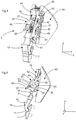
- the figure 1 partially illustrates a sports shoe 1 according to an embodiment of the invention.
- the sports boot is a ski boot particularly suitable for the practice of alpine skiing, ski touring, telemark, or even even the practice of snowboarding.
- the invention which will be described could be used for any type of sports shoe comprising an articulation and a removable locking means for this articulation.
- the ski boot 1 includes a shell bottom 2 able to wrap the foot below the ankle, and a collar 3 able to wrap the bottom of the leg above the ankle.
- the ski boot can also include a comfort boot (not shown) interposed between the bottom of the shell and the user's foot and between the collar and the user's foot, as well as tightening means (not shown). ) the collar around the bottom of the leg and / or the shell bottom around the foot.
- the shell bottom and the collar are each made of a wall, advantageously obtained by plastic injection.
- the ski boot 1 comprises a rotary joint 4 between the bottom of the shell 2 and the collar 3.
- the rotary joint 4 can be produced by means of bearings arranged in the bottom of the shell 2 and in the collar 3 These bearings are then positioned at the height of the internal malleolus and the external malleolus and cooperate with axes (not shown), such as screws or rivets.
- the axis A1 designates the axis of rotation of the collar around the bottom of the hull.
- the axis A1 is substantially parallel to the transverse axis Y.
- the ski boot 1 comprises a locking and unlocking device 5, particularly shown in the figure 3 , according to an embodiment of the invention.
- the locking and unlocking device 5 forms an interface between the bottom of the shell 2 and the collar 3. It makes it possible to block or release the articulation in rotation 4 between the bottom of the shell 2 and the collar 3.
- the locking device and unlocking 5 is positioned at the rear of the ski boot and takes place in a notch 6 in the bottom of the shell 2.
- the notch 6 is an opening made at the rear and in the upper part of the bottom of the shell. It can have a “V” shape or a “U” shape and is particularly visible on figures 2 , 6 and 12 .
- the locking and unlocking device 5 is fixed to the collar 3 and cooperates with the bottom of the shell 2 to block or release the articulation in rotation.
- the ski boot can therefore be found in two distinct configurations.
- a first configuration called the “ski” configuration
- the articulation in rotation between the bottom of the shell 2 and the collar 3 is blocked, and the transmission of the forces from the foot to the boot and to the ski is optimal.
- the articulation of his ankle is therefore blocked.
- a small amplitude in the ankle joint may remain due to the rigidity of the materials used for the manufacture of the ski boot.
- the articulation in rotation between the bottom of the shell 2 and the collar 3 is released, that is to say it is free, or in other words, not blocked.
- the range of motion of the ankle can nevertheless be limited by the front and rear stops of the ski boot, in particular between the bottom of the shell and the collar.
- the range of motion of the ankle inside the shoe in the running configuration may be less than the range of natural movement of the ankle. It is nevertheless greater than the range of motion of the ankle inside the boot in ski configuration.
- the ski boot 1 and its locking and unlocking device 5 in the ski configuration are illustrated on the figures 1 to 4 .
- Ski boot 1 and its device locking and unlocking 5 in run configuration are illustrated on the Figures 5 to 8 .
- the rocker 10 comprises a first end, oriented downwards, and a second end, oriented upwards.
- the first lower end is equipped with a hooking means 11 able to cooperate with the bottom of the shell when the rocker 10 is in the locked position.
- the bottom of the hull comprises at the rear and in the middle a groove 7 oriented transversely.
- This groove can form with the bottom of the shell 2 a one-piece assembly or else be an element fixed to the bottom of the shell.
- the groove 7 is an attached element fixed to the bottom of the shell by means of two cooperating inserts with two holes of corresponding shape in the bottom of the shell 2.
- the attachment means 11 is constituted by a protrusion extending substantially along the longitudinal axis.
- the protuberance takes place in the groove 7.
- the stop of the protuberance on an upper edge of the groove prevents the collar from pivoting forward.
- the stop of the protrusion on a lower edge of the groove prevents the collar from pivoting backwards.
- the attachment means 11 could be a recess or a groove, which cooperates with a protuberance of the bottom of the shell, thus preventing movements of the collar relative to the bottom of the shell.
- the second upper end of the rocker 10 is equipped with a first connecting means 12 to the torsion spring.
- the first connecting means 12 is formed by a transversely extending groove. This groove is substantially oriented upwards and receives a first end 31 of the torsion spring 30.
- the torsion spring 30 is always more or less constrained whatever the configuration of the ski boot.
- the first end 31 of the torsion spring remains in place in the groove without risk of escaping therefrom.
- the first end 31 of the spring can be fixed to the rocker could be made via a recess provided for this purpose at the end of the rocker.
- the means of connection 12 of the lever to the torsion spring could be arranged so that a larger part of the spring than its single end 31 cooperates with the lever 10.
- the lever 10 is movable between a locking position in which it blocks the rotation of the collar 3 relative to the bottom of the shell 2, and an unlocking position in which it releases the rotation of the collar 3 relative to the bottom of the shell 2.
- the locking position is illustrated in particular on the figure 4 and the unlocking position is illustrated in particular on the figure 8 .
- the hooking means 11 of the rocker 10 is released from the groove 6 of the bottom of the hull and is therefore no longer in contact with the bottom of the hull.
- the rocker is movable in rotation between its locked position and its unlocked position around a first axis of rotation 41 positioned between the first end and the second end.
- the first axis of rotation 41 is integral with the support 40 and extends parallel to the transverse axis Y.
- the first axis 41 is mounted in rotation on the support 40, itself fixed on the collar.
- the first axis 41 is therefore also mounted in rotation relative to the collar.
- the first axis 41 is closer to the second high end than to the first low end.
- the rocker 10 also comprises a protuberance, for example in the form of a tooth or an outer rim 13 serving to support a lower rim of the collar 3.
- the outer rim forms a protrusion extending longitudinally towards the rear and comprises a length of the order of magnitude of the thickness of the wall forming the collar.
- the lever 20 is a part, preferably in one piece, comprising a wheel 21 and a lever 22.
- the lever 22 constitutes a means of manual actuation of the device 5 for the user.
- the lever 20 is movable in rotation about a second axis of rotation 42, between a first position and a second position.
- the second axis of rotation 42 is integral with the support 40 and extends parallel to the transverse axis Y.
- the second axis 42 is mounted in rotation on the support 40, itself fixed on the collar.
- the second axis 42 is therefore also mounted in rotation relative to the collar.
- the second axis 42 also extends parallel to the first axis of rotation 41 of the lever 10.
- the first axis 41 and the second axis 42 are therefore positioned at a fixed distance from one another.
- the wheel 21 has the overall shape of a cylinder and the second axis of rotation 42 passes through the axis of revolution of this cylinder.
- the wheel 21 includes a second connecting means 23 cooperating with a second end 32 of the torsion spring.
- This second connecting means 23 is offset by relative to the axis of rotation of the wheel 21. According to the embodiment presented, it consists of a hole oriented transversely, and cooperating with the second end 32 of the spring 30.
- the wheel 21 also includes a third means link 24 cooperating with two link arms 60.
- the third link means 24 is formed by an axis oriented transversely and projecting from both sides of the wheel 21.
- the axis is eccentric relative to the center of the wheel 21 and is positioned substantially at the base of the handle 22.
- the two link arms 60 each comprise a circular hole 61 cooperating with this axis.
- the two link arms 60 could each have two protrusions or pins to cooperate with a recess / bore made in the wheel 21.
- the link arms 60 thus form a connection means between the lever 20 and the deflector 50, of which the operation will be detailed later.
- the wheel 21 may locally include a recess 25 making it possible in particular to avoid any interference from contact with the rear deflector during the rotation of the wheel 21, while reducing it.
- the handle 22 protrudes from the ski boot towards the rear.
- the lever 20 When the ski boot is in ski configuration, the lever 20 is in the first position and the lever 22 extends generally rearward and downward.
- the lever 20 When the ski boot is in the running configuration, the lever 20 is in the second position and the lever 22 extends generally backwards and upwards. Between the first position and the second position, the lever 20 can rotate around a quarter of a turn.
- the collar comprises an opening 8, at the rear, facing the lever 20 so that the lever is easily accessible.
- the joystick can be operated directly by hand or via the tip of a ski pole.
- the handle advantageously comprises an opening making it possible to block the tip of the ski pole.
- the opening can allow the passage of a strap, for example textile, facilitating the gripping of the lever by the user to actuate the device.
- the torsion spring 30, which could also be called a “pin spring”, comprises a set of turns 33 between the two ends 31, 32.
- the torsion spring 30 is an elastic means for torsion. It is designed to be stressed according to a torque parallel to the axis of turns.
- the turns are inscribed in a cylinder-shaped envelope whose axis of revolution is oriented transversely. Thus, the torsion spring is able to be biased according to a torque around an axis parallel to the transverse axis Y.
- the figure 9 illustrates in more detail the design of the spring.
- the set of turns 33 is broken down into two groups of turns 33A, 33B arranged transversely on either side of the first end 31.
- the torsion spring is produced from a single steel wire. The two ends of the steel wire are positioned at the second end 32 of the torsion spring, while the first end 31 of the torsion spring is formed by a middle part of the steel wire extending substantially transversely. According to a view in the longitudinal and vertical plane, the two ends 31, 32 of the torsion spring are arranged in a “V” shape with all of the turns 33 positioned at the tip of the “V”.
- the torsion spring can be stressed by tightening the two arms of the "V", that is to say by bringing the two ends 31, 32 closer to each other.
- the small free part between the two ends of the steel wire at the second end is positioned in the same longitudinal and vertical plane as the middle of the first end 31.
- the rocker 10, the lever 20 and the torsion spring 30 are arranged so that when the lever is in its first position, the rocker is in the locked position and when the lever is in its second position, the rocker is in the unlock position.
- the locking position and the unlocking position of the rocker are kept stable under the effect of the spring 30. That is to say that the torsion spring tends to keep the rocker in the position in which it is located.
- the second connecting means 23 to which the second end 32 of the torsion spring 30 is fixed describes a circular movement. According to this circular movement, the second end 32 of the torsion spring progressively approaches the first end 31, then reaches maximum approximation, then moves away from the first end 31.
- the rotation of the lever from the first position to the second position causes the torsion spring to be loaded by torsion in the winding direction of the turns, then to relax the torsion spring.
- the same loading phenomenon followed by detente occurs when the lever moves from the second position to the first position.
- the movement of the rocker is caused by a movement of the lever via the torsion spring.
- the force applied by the user to the lever is transmitted to the rocker via the torsion spring.
- the spring 30 is held only by its first end 31 connected to the rocker and by its second end 32 connected to the lever.
- the ends 32 of the spring are positioned in recesses or holes made in the rocker.
- the torsion spring is not in contact with other elements of the ski boot.
- the torsion spring 30 serves both to stabilize the locking and unlocking positions of the rocker, and at the same time to transmit a force on the lever to the rocker.
- the support 40 is an element of the locking and unlocking device 5 fixedly attached to the collar 3 and supporting various elements of the locking and unlocking device 5.
- the support 40 is interposed between the collar, which is behind it, and the rear deflector 50 which is in front, along the longitudinal axis.
- the locking and unlocking device 5 is therefore protected from the outside by the collar 3 and inside the shoe by the rear deflector 50.
- the support 40 is fixed to the collar 3 on the one hand via two circular holes 43 in top of the support through which can pass two screws or two rivets in engagement with the collar. On the other hand, it is fixed to the collar via the first axis 41.
- the first axis 41 not only serves as an axis of rotation for the rocker 10 but it also cooperates with two openings 9 arranged in the collar 3, as can be seen in particular on the figures 1 and 5 .
- the first axis of rotation 41 is fixed to the support 40 at a lower end of the support.
- the second axis of rotation 42 is fixed to the support 40 approximately halfway up the support 40.
- the support 40 comprises, at its upper end a bridge 44 in the shape of a "U" under which the elastic control means 70 can slide.
- the support also includes four oblong openings 45 extending substantially vertically. These oblong openings 45 cooperate with pins 51 of the rear deflector 50 to define a slide link oriented vertically between the support 40 and the rear deflector 50.
- the rear deflector 50 which could also be called "spoiler” according to the anglicism, is an element capable of enveloping the back of the lower leg, that is to say the bottom of the calf.
- the rear deflector is able to take position in the notch 6 formed at the rear of the bottom of the hull 2, as is particularly represented by the figures 12 to 14 .
- the rear deflector includes a curved shape to match the natural shape of the calf.
- the rear deflector 50 is slidably mounted vertically relative to the support 40, and therefore indirectly relative to the collar 3.
- the four pins 51 fixed on a rear face of the rear deflector, cooperate with the four oblong openings 45 of the support 40.
- the rear deflector 50 is movable between a low position and a high position. In the low position, or ski position, the rear deflector closes, in other words mouth or roof, the notch 6 at the rear of the bottom of the shell 2, as shown by the figure 13 . In the low position, the rear deflector extends the natural curvature of the bottom of the shell 2. In the high position, or operating position, the rear deflector 50 releases or at least partially reveals the notch 6, as shown by the figure 14 .
- the two link arms 60 connect the rear deflector to the lever, so that the first position of the lever keeps the rear deflector in its low position and the second position of the lever keeps the rear deflector in its high position.
- the two link arms 60 extend from the wheel 21 to the elastic control means 70, itself connected to the rear deflector 50.
- the two link arms 60 are substantially identical and are arranged vertically on either side. of the wheel 21.
- Each arm comprises two circular holes 61, 62 at each of its two ends.
- the first circular hole 61 cooperates with the third connection means 24 of the wheel 21.
- the second circular hole 62 cooperates with a fourth connection means 71, particularly visible on the figure 8 , integral with the elastic control means 70.
- the fourth connection means 71 is formed by two pins extending transversely on either side of the elastic control means 70. Note, the link arms have a curved shape allowing bypass the second axis of rotation 42. Thus, the two link arms 60 do not come into contact with the second axis of rotation 42 whatever the position of the lever 20.
- the third connecting means 24 moves upwards.
- the two link arms 60 also move upwards.
- the elastic control means 70 and the rear deflector 50 then translate upwards according to the slide connection imposed by the cooperation of the pins 51 with the oblong openings 45.
- the rear deflector then at least partially releases the notch 6 formed in the rear of hull bottom 2, as shown in figure 14 .
- the rear deflector descends and fills the notch of the bottom of the hull, as shown in figure 13 . That is to say that the edges of the rear deflector 50 match the edges 66 of the notch 6, thus completing the wall of the bottom of the hull to form an assembly substantially equivalent to a continuous hull bottom, without indentation.
- the rear deflector 50 further comprises two lateral surfaces 55 intended to come to bear on the rear surface of the bottom of the shell, then a central part in relief intended to occupy the free space of the notch 6
- This raised part forms two lateral raised surfaces 54 intended to come into abutment against the surfaces arranged in the thickness of the lateral walls of the notch, at the edges 66 of this notch.
- These raised lateral surfaces 54 are oriented in a direction substantially perpendicular to the lateral surfaces 55, these two surfaces joined together thus forming a shoulder. The latter guarantees the correct positioning and good maintenance of the rear deflector relative to the bottom of the hull in the two longitudinal x and transverse y directions in the ski practice position.
- connection by double shoulder-type stop between the spoiler and the bottom of the hull allows the latter to overall have a rigidity similar to that of the shell bottom of the state of the art without indentation.
- the lateral surfaces 55 form fins covering the rear surface of the bottom of the hull, participating in the stop and cooperation function of the rear deflector and the bottom of the hull.
- the rear deflector could have another shape, in particular at the level of its bearing surfaces forming a shoulder-type stop on the shell. Indeed, any other configuration making it possible to obtain a stop in the two longitudinal x and transverse y directions could be suitable, even by means of a single inclined bearing surface.
- the shoulder described could have another shape.
- the abutment of the rear deflector could exist only in the only longitudinal direction, to guarantee that the rear deflector does not pass through the notch 6 towards the interior of the bottom of the hull, where it would risk hit the skier's leg.
- the elastic control means 70 is an element of the locking and unlocking device 5 intermediate between the two link arms 60 and the rear deflector 50. It has a substantially parallelepiped shape and can slide under the bridge 45 of the support 40. It is capable of damping a displacement of the rear deflector downward or upward relative to the collar 3. The rear deflector is movable relative to the elastic control means 70 upwards and downwards from an intermediate position.
- the elastic control means 70 is notably shown in the figures 10 and 11 . It includes a slider 72 capable of sliding vertically relative to the rear deflector and an elastic means 73, in particular a spring.
- the cursor 72 includes two vertically oriented grooves 74. These grooves 74 cooperate with two upper projections 52 and two lower projections 53 present on the back of the rear deflector 50. Between the two grooves 74, the slider 72 comprises a high stop 75 and a low stop 76.
- the elastic means 73 is housed at the inside the slider 72.
- an upper end of the elastic means 73 is supported on the upper stop 75 and on the upper projections 52, and a lower end of the elastic means 73 is supported on the lower stop 76 and on the lower projections 53.
- the elastic means can already be partially compressed in order to prevent it from moving.
- an upwardly directed constraint is exerted on the rear deflector 50, it moves upward relative to the cursor.
- the projections 52, 53 slide in the grooves 74.
- the upper end of the elastic means 73 is supported only on the upper stop 75, and the lower end of the elastic means 73 is supported only on the lower projections 53.
- the upper and lower stops 75, 76 each comprise a means for retaining the elastic means (in this case, a spout bearing longitudinally on each end of the elastic means 73) so as to keep the elastic means in place at the inside the cursor.
- the rear deflector 50 is suspended relative to the collar 3.
- the vertical movement of the rear deflector obtained by means of suspension 70 is added to the vertical movement of the rear deflector obtained by means of the lever 20 and the link arms 60.
- the notch 6 and the rear deflector can be dimensioned so that the rear deflector can move downwards via the suspension means 70 even when the ski boot is in ski configuration. Thus the comfort of the user is increased both in ski configuration and in walking configuration.
- a ski boot equipped with a locking and unlocking device that is reliable, stable, light, compact and simple to handle.
- a locking / unlocking element of the collar and a synchronized rear deflector makes it possible to increase the amplitude of the articulation between the collar and the shell of the shoe in the walking phase, improving thus the comfort of the shoe, as explained above.
- the notch of the bottom of the hull is positioned in the upper rear part, and takes up sufficient surface area to obtain the desired effect. For this, it extends over at least one third of the height of the bottom of the hull in its rear part. It also has sufficient lateral opening to release the lower leg.
- the rear deflector may include any shape other than the aforementioned V or U shape.
- the bottom of the hull can likewise take any complementary shape, in particular its notch positioned at its upper end in the rear part.
- the locking and unlocking device has been described with a lever.
- any actuating element which controls, preferably simultaneously, the movements of a rear deflector and a rocker, could be used.
- the device has been described with a rocker: the latter could be in another form, forming a lock, capable of blocking the rotation of the collar relative to the bottom of the shell.
- the spring connecting the lever to the rocker, and therefore more generally the actuating element to the lock could present itself differently. It could be elongated, its turns being oriented in a direction perpendicular to the torsion spring shown. It could be any other jurisdiction.
- the rear deflector and the latch are separate. They come in the form of two separate parts, not in the form of a single unit.
- the locking and unlocking device therefore comprises a first mechanical connection between the actuating element and the latch, and a second mechanical connection, distinct from the first mechanical connection, between the actuating element and the rear deflector.
- the locking / unlocking device responds to the technical problem of improving walking by means of a rear deflector 50 movable opposite a notch of a bottom of sports shoe shell.
- a device comprising only a deflector and a mechanism allowing its mobility, preferably by translation or sliding, between at least two positions, also provides an interesting response to the technical problem of improving walking.
- the invention also relates to a device, characterized in that it comprises a rear deflector movable in translation between a low position and a high position, so as to cooperate with a notch in a bottom of the shell by closing this notch in the low position, and at least partially releasing this notch in the high position.
- This device can include any actuation means, that described above on the basis of the lever 20, or any other mechanism, in particular without the lever described above and / or with a different spring, acting only on the lever.
- Said device can comprise an elastic control means 70 capable of damping a displacement of the rear deflector 50 downwards or upwards relative to a collar 3.
- Said elastic control means 70 may comprise a slider 72 able to slide vertically relative to the rear deflector 50 and an elastic means 73, in particular a spring, the elastic means 73 comprising two ends, each end of the elastic means being able to bear either on the slider 72 is on the rear deflector 50 so that the elastic means 73 are always stressed in compression when the rear deflector 50 moves down relative to the slider 72 or when the rear deflector 50 moves upwards by relative to cursor 72.
- the device may comprise a support 40 on which is mounted the means for actuating the rear deflector, and comprising at least one groove 45 capable of guiding the rear deflector 50 along a sliding connection.
- the rear deflector may have a curved shape intended to wrap around the back of a leg.
Abstract
Dispositif de verrouillage et déverrouillage (5) pour former une interface entre un bas de coque (2) et un collier (3) d'une chaussure de sport (1) dans laquelle le collier (3) est articulé en rotation autour du bas de coque (2), caractérisé en ce que le dispositif de verrouillage et déverrouillage (5) comprend un élément d'actionnement, un verrou et un déflecteur arrière (50), ledit élément d'actionnement étant mobile entre une première position et une deuxième position, contrôlant la position du verrou et la position du déflecteur arrière (50) de sorte que :- Dans la première position dudit élément d'actionnement, le verrou occupe une position de verrouillage dans laquelle le verrou est apte à bloquer la rotation d'un collier (3) par rapport à un bas de coque (2), et le déflecteur arrière (50) occupe une position basse dans laquelle il est apte à obturer une échancrure (6) à l'arrière d'un bas de coque (2),- Dans la deuxième position dudit élément d'actionnement, le verrou occupe une position de déverrouillage dans laquelle le verrou est apte à libérer la rotation d'un collier (3) par rapport à un bas de coque (2), et le déflecteur arrière (50) occupe une position haute dans laquelle il est apte à dégager au moins partiellement une échancrure (6) à l'arrière d'un bas de coque (2) pour augmenter l'amplitude de flexion d'un bas de jambe dans une chaussure de sport (1).Locking and unlocking device (5) for forming an interface between a shell bottom (2) and a collar (3) of a sports shoe (1) in which the collar (3) is articulated in rotation around the bottom of shell (2), characterized in that the locking and unlocking device (5) comprises an actuating element, a latch and a rear deflector (50), said actuating element being movable between a first position and a second position , controlling the position of the bolt and the position of the rear deflector (50) so that: - In the first position of said actuating element, the bolt occupies a locking position in which the bolt is capable of blocking the rotation of a collar (3) relative to a shell bottom (2), and the rear deflector (50) occupies a low position in which it is able to close a notch (6) at the rear of a shell bottom (2 ), - In the second position of said actuating element, the lock occupies a unlocking position in which the bolt is capable of releasing the rotation of a collar (3) relative to a shell bottom (2), and the rear deflector (50) occupies a high position in which it is capable of releasing at at least partially a notch (6) at the rear of a shell bottom (2) to increase the amplitude of flexion of a lower leg in a sports shoe (1).
Description
L'invention concerne un dispositif de verrouillage et déverrouillage pour former une interface entre un bas de coque et un collier d'une chaussure de sport, notamment d'une chaussure de ski, le collier étant articulé en rotation autour du bas de coque. L'invention porte aussi sur une chaussure de sport, notamment une chaussure de ski comprenant un tel un dispositif de verrouillage et déverrouillage.The invention relates to a locking and unlocking device for forming an interface between a shell bottom and a collar of a sports boot, in particular a ski boot, the collar being articulated in rotation around the shell bottom. The invention also relates to a sports boot, in particular a ski boot comprising such a locking and unlocking device.
Pour la pratique du ski on connaît des chaussures de sport comprenant un bas de coque et un collier articulé en rotation autour du bas de coque. Le bas de coque enveloppe le pied en dessous de la cheville tandis que le collier enveloppe le bas de la jambe au-dessus de la cheville. L'articulation entre le bas de coque et le collier permet une insertion aisée du pied dans la chaussure, ainsi qu'une marche naturelle puisque l'articulation de la cheville n'est pas bloquée. Lorsque la chaussure est utilisée en descente pour la pratique du ski alpin, l'articulation entre le bas de coque et le collier doit être bloquée afin de contrôler efficacement les skis.For the practice of skiing, sports shoes are known comprising a bottom of the shell and a collar articulated in rotation around the bottom of the shell. The shell bottom wraps the foot below the ankle while the collar wraps the bottom of the leg above the ankle. The articulation between the bottom of the shell and the collar allows easy insertion of the foot into the shoe, as well as natural walking since the ankle joint is not blocked. When the boot is used downhill for alpine skiing, the joint between the bottom of the shell and the collar must be blocked in order to effectively control the skis.
Afin de bloquer ou de libérer l'articulation entre le bas de coque et le collier, on connaît l'utilisation d'un dispositif de verrouillage et déverrouillage, également dénommé selon l'anglicisme « ski-walk ». Ces dispositifs comprennent un levier actionnable à la main et permettant de choisir entre deux configurations de la chaussure. La première configuration, dite « ski », bloque l'articulation entre le collier et le bas de coque. La deuxième configuration, dite « walk » ou « marche », libère l'articulation entre le collier et le bas de coque.In order to block or release the articulation between the bottom of the shell and the collar, the use of a locking and unlocking device is also known, also known in English terms as "ski-walk". These devices include a lever operable by hand and allowing to choose between two configurations of the shoe. The first configuration, called "ski", blocks the articulation between the collar and the bottom of the hull. The second configuration, called "walk" or "walk", frees the articulation between the collar and the bottom of the hull.
Toutefois les dispositifs de verrouillage et déverrouillage connus de l'état de la technique comprennent tout ou partie des inconvénients suivant :
- ils sont complexes à fabriquer ;
- ils ont une fiabilité limitée, c'est-à-dire qu'ils peuvent se casser et/ou s'user facilement ou passer intempestivement d'une configuration à l'autre ;
- ils sont lourds et/ou volumineux ;
- ils sont difficiles à manipuler ;
- ils ne permettent pas d'atteindre une amplitude de mouvement suffisante pour atteindre un confort de marche satisfaisant.
- they are complex to manufacture;
- they have limited reliability, that is to say that they can break and / or wear out easily or inadvertently pass from one configuration to another;
- they are heavy and / or bulky;
- they are difficult to handle;
- they do not allow a sufficient range of motion to be reached to achieve satisfactory walking comfort.
Le but de l'invention est de fournir un dispositif de verrouillage et déverrouillage remédiant aux inconvénients ci-dessus et améliorant les dispositifs de verrouillage et déverrouillage connus de l'art antérieur. En particulier, l'invention permet de réaliser des dispositifs de verrouillage et déverrouillage qui soient simples à fabriquer, fiables, robustes, légers, compacts, et faciles à manipuler. Un autre objectif de l'invention est de permettre d'atteindre une configuration de marche permettant une amplitude de mouvement suffisante pour le confort de l'utilisateur.The object of the invention is to provide a locking and unlocking device overcoming the above drawbacks and improving the locking and unlocking devices known from the prior art. In particular, the invention makes it possible to produce locking and unlocking devices which are simple to manufacture, reliable, robust, light, compact, and easy to handle. Another objective of the invention is to make it possible to achieve a walking configuration allowing a range of motion sufficient for the comfort of the user.
A cet effet, l'invention repose sur un dispositif de verrouillage et déverrouillage pour former une interface entre un bas de coque et un collier d'une chaussure de sport dans laquelle le collier est articulé en rotation autour du bas de coque, caractérisé en ce que le dispositif de verrouillage et déverrouillage comprend un élément d'actionnement, un verrou et un déflecteur arrière, ledit élément d'actionnement étant mobile entre une première position et une deuxième position, contrôlant la position du verrou et la position du déflecteur arrière de sorte que :
- Dans la première position dudit élément d'actionnement, le verrou occupe une position de verrouillage dans laquelle le verrou est apte à bloquer la rotation d'un collier par rapport à un bas de coque, et le déflecteur arrière occupe une position basse dans laquelle il est apte à obturer une échancrure à l'arrière d'un bas de coque,
- Dans la deuxième position dudit élément d'actionnement, le verrou occupe une position de déverrouillage dans laquelle le verrou est apte à libérer la rotation d'un collier par rapport à un bas de coque, et le déflecteur arrière occupe une position haute dans laquelle il est apte à dégager au moins partiellement une échancrure à l'arrière d'un bas de coque pour augmenter l'amplitude de flexion d'un bas de jambe dans une chaussure de sport.
- In the first position of said actuating element, the bolt occupies a locking position in which the bolt is capable of blocking the rotation of a collar relative to a bottom of the shell, and the rear deflector occupies a low position in which it is capable of sealing a notch at the rear of a bottom of the hull,
- In the second position of said actuating element, the bolt occupies an unlocking position in which the bolt is capable of releasing the rotation of a collar relative to a bottom of the shell, and the rear deflector occupies a high position in which it is able to at least partially release a notch at the rear of a shell bottom to increase the amplitude of flexion of a lower leg in a sports shoe.
L'invention porte aussi sur une chaussure de sport en tant que telle, notamment une chaussure de ski, comprenant un tel dispositif de verrouillage et déverrouillage.The invention also relates to a sports boot as such, in particular a ski boot, comprising such a locking and unlocking device.
L'invention est plus précisément définie par les revendications.The invention is more precisely defined by the claims.
Ces objets, caractéristiques et avantages de la présente invention seront exposés en détail dans la description suivante d'un mode d'exécution particulier fait à titre non-limitatif en relation avec les figures jointes parmi lesquelles :
- La
figure 1 est une vue isométrique partielle d'une chaussure de ski en configuration « ski » selon un mode de réalisation de l'invention. - La
figure 2 est une vue isométrique de l'intérieur de la chaussure de ski en configuration « ski ». - La
figure 3 est une vue isométrique d'un dispositif de verrouillage et déverrouillage en configuration « ski » selon un mode de réalisation de l'invention. - La
figure 4 est une vue de profil du dispositif de verrouillage et déverrouillage en configuration « ski ». - La
figure 5 est une vue isométrique partielle de la chaussure de ski en configuration « marche ». - La
figure 6 est une vue isométrique de l'intérieur de la chaussure de ski en configuration « marche ». - La
figure 7 est une vue isométrique du dispositif de verrouillage et déverrouillage en configuration « marche » et d'un bas de coque de la chaussure de ski. - La
figure 8 est une vue de profil du dispositif de verrouillage et déverrouillage en configuration « marche ». - La
figure 9 est une vue isométrique d'un ressort de torsion du dispositif de verrouillage et déverrouillage. - La
figure 10 illustre partiellement un déflecteur arrière du dispositif de verrouillage et déverrouillage. - La
figure 11 illustre partiellement un support et un curseur du dispositif de verrouillage et déverrouillage. - La
figure 12 illustre une vue arrière d'une partie d'un bas de coque d'une chaussure de sport selon un mode de réalisation de l'invention. - La
figure 13 illustre une vue depuis l'avant d'une partie d'un bas de coque d'une chaussure de sport dont l'échancrure est obturée par un déflecteur arrière selon un mode de réalisation de l'invention. - La
figure 14 illustre une vue depuis l'avant d'une partie d'un bas de coque d'une chaussure de sport dont l'échancrure est partiellement libérée par le déflecteur arrière selon le mode de réalisation de l'invention.
- The
figure 1 is a partial isometric view of a ski boot in “ski” configuration according to an embodiment of the invention. - The
figure 2 is an isometric view of the interior of the ski boot in “ski” configuration. - The
figure 3 is an isometric view of a locking and unlocking device in the “ski” configuration according to an embodiment of the invention. - The
figure 4 is a side view of the locking and unlocking device in the “ski” configuration. - The
figure 5 is a partial isometric view of the ski boot in the "walking" configuration. - The
figure 6 is an isometric view of the interior of the ski boot in "walking" configuration. - The
figure 7 is an isometric view of the locking and unlocking device in the "walking" configuration and of a shell of the ski boot. - The
figure 8 is a side view of the locking and unlocking device in the "on" configuration. - The
figure 9 is an isometric view of a torsion spring of the locking and unlocking device. - The
figure 10 partially illustrates a rear deflector of the locking and unlocking device. - The
figure 11 partially illustrates a support and a slider for the locking and unlocking device. - The
figure 12 illustrates a rear view of a portion of a shell bottom of a sports shoe according to an embodiment of the invention. - The
figure 13 illustrates a view from the front of part of a shell bottom of a sports shoe whose notch is closed by a rear deflector according to an embodiment of the invention. - The
figure 14 illustrates a view from the front of a portion of a shell bottom of a sports shoe whose notch is partially released by the rear deflector according to the embodiment of the invention.
Sur l'ensemble des figures et de la description, on considère une chaussure reposant via sa semelle sur un sol horizontal. L'axe X désigne l'axe longitudinal. En progression vers l'avant et en ligne droite, un utilisateur de la chaussure progresse de l'arrière vers l'avant selon une direction parallèle à l'axe longitudinal X. L'axe X est orienté de l'arrière vers l'avant. L'axe Y désigne l'axe transversal de l'utilisateur. L'axe Y est orienté de la gauche vers la droite selon le point de vue de l'utilisateur. L'axe Z désigne l'axe perpendiculaire à l'axe X et à l'axe Y. L'axe Z est un axe vertical lorsque l'utilisateur est sur un sol horizontal. L'axe Z est orienté de bas en haut. Les axes X, Y et Z forment un repère orthogonal.In all of the figures and the description, a shoe is considered to rest via its sole on a horizontal floor. The X axis designates the longitudinal axis. In progression forward and in a straight line, a user of the shoe progresses from rear to front in a direction parallel to the longitudinal axis X. The axis X is oriented from rear to front . The Y axis designates the transverse axis of the user. The Y axis is oriented from left to right according to the user's point of view. The Z axis designates the axis perpendicular to the X axis and the Y axis. The Z axis is a vertical axis when the user is on horizontal ground. The Z axis is oriented from bottom to top. The X, Y and Z axes form an orthogonal coordinate system.
La
La chaussure de ski 1 comprend un bas de coque 2 apte à envelopper le pied en dessous de la cheville, et un collier 3 apte à envelopper le bas de la jambe au-dessus de la cheville. La chaussure de ski peut également comprendre un chausson de confort (non représenté) intercalé entre le bas de coque et le pied de l'utilisateur et entre le collier et le pied de de l'utilisateur, ainsi que des moyens de serrage (non représentés) du collier autour du bas de la jambe et/ou du bas de coque autour du pied. Le bas de coque et le collier sont faits chacun d'une paroi, avantageusement obtenue par injection plastique. La chaussure de ski 1 comprend une articulation en rotation 4 entre le bas de coque 2 et le collier 3. En particulier, l'articulation en rotation 4 peut être réalisée grâce à des paliers aménagés dans le bas de coque 2 et dans le collier 3. Ces paliers sont alors positionnés à hauteur de la malléole interne et de la malléole externe et coopèrent avec des axes (non représentés), tels que des vis ou des rivets. L'axe A1 désigne l'axe de rotation du collier autour du bas de coque. L'axe A1 est sensiblement parallèle à l'axe transversal Y.The
La chaussure de ski 1 comprend un dispositif de verrouillage et déverrouillage 5, particulièrement représenté sur la
Le dispositif de verrouillage et déverrouillage 5 est fixé au collier 3 et coopère avec le bas de coque 2 pour bloquer ou libérer l'articulation en rotation. La chaussure de ski peut donc se trouver dans deux configurations distinctes. Dans une première configuration, dite configuration « ski », l'articulation en rotation entre le bas de coque 2 et le collier 3 est bloquée, et la transmission des efforts du pied à la chaussure et au ski est optimale. Lorsque l'utilisateur a un pied à l'intérieur de la chaussure en configuration ski, l'articulation de sa cheville est donc bloquée. En remarque, une faible amplitude dans l'articulation de la cheville peut demeurer du fait de la rigidité des matériaux utilisés pour la fabrication de la chaussure de ski. Dans une deuxième configuration, dite configuration « marche », l'articulation en rotation entre le bas de coque 2 et le collier 3 est libérée, c'est-à-dire qu'elle est libre, ou autrement dit, non bloquée. Lorsque l'utilisateur a un pied à l'intérieur de la chaussure en configuration marche, il peut faire bouger l'articulation de sa cheville ce qui lui permet de marcher avec les chaussures de ski ou de progresser sur la neige avec les skis chaussés, notamment dans la pratique du ski de randonnée. En remarque, l'amplitude de mouvement de la cheville peut néanmoins être limitée par des butées avant et arrière de la chaussure de ski, notamment entre le bas de coque et le collier. Ainsi l'amplitude de mouvement de la cheville à l'intérieur de la chaussure en configuration marche peut être inférieure à l'amplitude de mouvement naturelle de la cheville. Elle est néanmoins supérieure à l'amplitude de mouvement de la cheville à l'intérieur de la chaussure en configuration ski. La chaussure de ski 1 et son dispositif de verrouillage et déverrouillage 5 en configuration ski sont illustrés sur les
En référence aux
- une bascule 10,
un levier 20,- un ressort de torsion 30,
un support 40,- un déflecteur arrière 50,
- deux bras de
liaison 60, et - un moyen de contrôle élastique 70.
- a
rocker 10, - a
lever 20, - a
torsion spring 30, - a
support 40, - a
rear deflector 50, - two link
arms 60, and - an elastic control means 70.
En remarque, le support 40 n'est pas représenté sur la
La bascule 10 comprend une première extrémité, orientée vers le bas, et une deuxième extrémité, orientée vers le haut. La première extrémité basse est équipée d'un moyen d'accroche 11 apte à coopérer avec le bas de coque lorsque la bascule 10 est en position de verrouillage. Plus précisément le bas de coque comprend à l'arrière et au milieu une rainure 7 orientée transversalement. Cette rainure peut former avec le bas de coque 2 un ensemble monobloc ou bien être un élément fixé au bas de coque. Selon le mode de réalisation illustré, la rainure 7 est un élément rapporté fixé au bas de coque par l'intermédiaire de deux inserts coopérants avec deux trous de forme correspondante dans le bas de coque 2. Le moyen d'accroche 11 est constitué par une protubérance s'étendant sensiblement selon l'axe longitudinal. Lorsque la chaussure de ski est en configuration ski, la protubérance prend place dans la rainure 7. La butée de la protubérance sur un bord supérieur de la rainure empêche le collier de pivoter vers l'avant. La butée de la protubérance sur un bord inférieur de la rainure empêche le collier de pivoter vers l'arrière. Par conséquent lorsque la protubérance est en place à l'intérieur de la rainure, l'articulation entre le bas de coque et le collier de la chaussure de ski est bloquée. En variante, il serait possible d'envisager toute autre forme pour la coopération entre la bascule et le bas de coque. Par exemple, le moyen d'accroche 11 pourrait être un évidement ou une rainure, qui coopère avec une protubérance du bas de coque, empêchant ainsi les mouvements du collier par rapport au bas de coque.The
La deuxième extrémité haute de la bascule 10 est équipée d'un premier moyen de liaison 12 au ressort de torsion. Plus précisément, le premier moyen de liaison 12 est formé par une rainure s'étendant transversalement. Cette rainure est sensiblement orientée vers le haut et accueille une première extrémité 31 du ressort de torsion 30. Avantageusement, le ressort de torsion 30 est toujours plus ou moins contraint quelle que soit la configuration de la chaussure de ski. Ainsi la première extrémité 31 du ressort de torsion demeure en place dans la rainure sans risque de s'en échapper. En variante, la fixation de la première extrémité 31 du ressort à la bascule pourrait se faire via un évidement prévu à cet effet au niveau de l'extrémité de la bascule. En variante encore, le moyen de liaison 12 de la bascule au ressort de torsion pourrait être agencé de sorte qu'une partie plus importante du ressort que sa seule extrémité 31 coopère avec la bascule 10.The second upper end of the
La bascule 10 est mobile entre une position de verrouillage dans laquelle elle bloque la rotation du collier 3 par rapport au bas de coque 2, et une position de déverrouillage dans laquelle elle libère la rotation du collier 3 par rapport au bas de coque 2. La position de verrouillage est notamment illustrée sur la
En outre, la bascule 10 comprend également une protubérance, par exemple sous la forme d'une dent ou d'un rebord extérieur 13 servant d'appui à un rebord inférieur du collier 3. Le rebord extérieur forme une saillie s'étendant longitudinalement vers l'arrière et comprend une longueur de l'ordre de grandeur de l'épaisseur de la paroi formant le collier.In addition, the
Le levier 20 est une pièce, de préférence monobloc, comprenant une roue 21 et une manette 22. La manette 22 constitue un moyen d'actionnement manuel du dispositif 5 pour l'utilisateur. Le levier 20 est mobile en rotation autour d'un deuxième axe de rotation 42, entre une première position et une deuxième position. Le deuxième axe de rotation 42 est solidaire du support 40 et s'étend parallèlement à l'axe transversal Y. Le deuxième axe 42 est monté en rotation sur le support 40, lui-même fixé sur le collier. Le deuxième axe 42 est donc aussi monté en rotation par rapport au collier. Le deuxième axe 42 s'étend également parallèlement au premier axe de rotation 41 de la bascule 10. Le premier axe 41 et le deuxième axe 42 sont donc positionnés à une distance fixe l'un par rapport à l'autre. La roue 21 a globalement la forme d'un cylindre et le deuxième axe de rotation 42 passe par l'axe de révolution de ce cylindre. La roue 21 comprend un deuxième moyen de liaison 23 coopérant avec une deuxième extrémité 32 du ressort de torsion. Ce deuxième moyen de liaison 23 est excentré par rapport à l'axe de rotation de la roue 21. Selon le mode de réalisation présenté, il est constitué d'un trou orienté transversalement, et coopérant avec la deuxième extrémité 32 du ressort 30. Enfin, la roue 21 comprend également un troisième moyen de liaison 24 coopérant avec deux bras de liaison 60. Le troisième moyen de liaison 24 est formé par un axe orienté transversalement et faisant saillie des deux côtés de la roue 21. L'axe est excentré par rapport au centre de la roue 21 et est positionné sensiblement à la base de la manette 22. Les deux bras de liaison 60 comprennent chacun un trou circulaire 61 coopérant avec cet axe. En variante, les deux bras de liaison 60 pourraient comporter chacun deux protubérances ou goupilles pour coopérer avec un évidement/alésage réalisé dans la roue 21. Les bras de liaison 60 forment ainsi un moyen de liaison entre le levier 20 et le déflecteur 50, dont le fonctionnement sera détaillé par la suite. En remarque, la roue 21 peut comprendre localement un évidement 25 permettant notamment d'éviter toute interférence de contact avec le déflecteur arrière lors de la rotation de la roue 21, tout en l'allégeant.The
La manette 22 fait saillie de la chaussure de ski vers l'arrière. Lorsque la chaussure de ski est en configuration ski, le levier 20 est dans la première position et la manette 22 s'étend globalement vers l'arrière et vers le bas. Lorsque la chaussure de ski est en configuration marche, le levier 20 est dans la deuxième position et la manette 22 s'étend globalement vers l'arrière et vers le haut. Entre la première position et la deuxième position, le levier 20 peut effectuer une rotation d'environ un quart de tour. Avantageusement, le collier comprend une ouverture 8, à l'arrière, en vis-à-vis du levier 20 de sorte que la manette soit facilement accessible. La manette peut être actionnée directement à la main ou via la pointe d'un bâton de ski. A cet effet, la manette comprend avantageusement une ouverture permettant de bloquer la pointe du bâton de ski. Dans une variante, l'ouverture peut permettre le passage d'une sangle, par exemple textile, facilitant la préhension du levier par l'utilisateur pour actionner le dispositif.The
Le ressort de torsion 30, que l'on pourrait également dénommer « ressort à épingle », comprend un ensemble de spires 33 entre les deux extrémités 31, 32. Le ressort de torsion 30 est un moyen élastique en torsion. Il est conçu pour être sollicité suivant un couple de rotation parallèle à l'axe de spires. Les spires sont inscrites dans une enveloppe en forme de cylindre dont l'axe de révolution est orienté transversalement. Ainsi, le ressort de torsion est apte à être sollicité selon un couple de rotation autour d'un axe parallèle à l'axe transversal Y.The
La
La bascule 10, le levier 20 et le ressort de torsion 30 sont agencés de sorte que lorsque le levier est dans sa première position, la bascule est dans la position de verrouillage et lorsque le levier est dans sa deuxième position, la bascule est dans la position de déverrouillage. La position de verrouillage et la position de déverrouillage de la bascule sont maintenues stables sous l'effet du ressort 30. C'est-à-dire que le ressort de torsion tend à maintenir la bascule dans la position dans laquelle elle se trouve. En effet, lorsque le levier passe de la première position à la deuxième position, le deuxième moyen de liaison 23 auquel est fixée la deuxième extrémité 32 du ressort de torsion 30 décrit un mouvement circulaire. Selon ce mouvement circulaire, la deuxième extrémité 32 du ressort de torsion se rapproche progressivement de la première extrémité 31, puis atteint un rapprochement maximal, puis s'écarte de la première extrémité 31. Par conséquent, la rotation du levier de la première position à la deuxième position entraîne un chargement du ressort de torsion par torsion dans le sens d'enroulement des spires, puis une détente du ressort de torsion. Le même phénomène de chargement suivi d'une détente se produit lorsque le levier passe de la deuxième position à la première position. Ainsi, la position de verrouillage et la position de déverrouillage de la bascule sont des positions de la bascule dans lesquelles le ressort de torsion accumule le moins d'énergie, et ces positions sont donc des positions stables.The
Le déplacement de la bascule est entraîné par un déplacement du levier par l'intermédiaire du ressort de torsion. L'effort appliqué par l'utilisateur sur le levier est transmis à la bascule par l'intermédiaire du ressort de torsion. Il n'y a donc pas de contact direct entre la bascule et le levier ni de pièce rigide interposée entre le levier et la bascule transmettant à la bascule l'effort appliqué par l'utilisateur sur le levier. Le ressort 30 est maintenu uniquement par sa première extrémité 31 reliée à la bascule et par sa deuxième extrémité 32 reliée au levier. Les extrémités 32 du ressort sont positionnées dans des évidements ou trous réalisés dans la bascule. Le ressort de torsion n'est pas en contact avec d'autres éléments de la chaussure de ski. Finalement, le ressort de torsion 30 sert à la fois à stabiliser les positions de verrouillage et de déverrouillage de la bascule, et à la fois à transmettre un effort sur le levier à la bascule.The movement of the rocker is caused by a movement of the lever via the torsion spring. The force applied by the user to the lever is transmitted to the rocker via the torsion spring. There is therefore no direct contact between the lever and the lever nor any rigid part interposed between the lever and the lever transmitting to the lever the force applied by the user to the lever. The
Le support 40 est un élément du dispositif de verrouillage et déverrouillage 5 fixé solidairement au collier 3 et supportant différents éléments du dispositif de verrouillage et déverrouillage 5. Le support 40 est interposé entre le collier, qui est derrière lui, et le déflecteur arrière 50 qui est devant, suivant l'axe longitudinal. Le dispositif de verrouillage et déverrouillage 5 est donc protégé de l'extérieur par le collier 3 et à l'intérieur de la chaussure par le déflecteur arrière 50. Le support 40 est fixé au collier 3 d'une part via deux trous circulaire 43 en haut du support au travers desquels peuvent passer deux vis ou deux rivets en prise avec le collier. D'autre part, il est fixé au collier par l'intermédiaire du premier axe 41. En effet, le premier axe 41 sert non seulement d'axe de rotation pour la bascule 10 mais il coopère également avec deux ouvertures 9 aménagées dans le collier 3, comme cela est notamment visible sur les
Le déflecteur arrière 50, que l'on pourrait également dénommer selon l'anglicisme « spoiler », est un élément apte à envelopper l'arrière du bas de la jambe, c'est-à-dire le bas du mollet. Le déflecteur arrière est apte à prendre position dans l'échancrure 6 pratiquée à l'arrière du bas de coque 2, comme cela est particulièrement représenté par les
Ce déplacement du déflecteur arrière 50 va maintenant être détaillé. Les deux bras de liaison 60 relient le déflecteur arrière au levier, de sorte que la première position du levier maintient le déflecteur arrière dans sa position basse et la deuxième position du levier maintient le déflecteur arrière dans sa position haute. Les deux bras de liaison 60 s'étendent de la roue 21 jusqu'au moyen de contrôle élastique 70, lui-même relié au déflecteur arrière 50. Les deux bras de liaison 60 sont sensiblement identiques et sont agencés verticalement de part et d'autre de la roue 21. Chaque bras comprend deux trous circulaires 61, 62 à chacune de ses deux extrémités. Le premier trou circulaire 61 coopère avec le troisième moyen de liaison 24 de la roue 21. Le deuxième trou circulaire 62 coopère avec un quatrième moyen de liaison 71, particulièrement visible sur la
Lorsque le levier 20 est déplacé de sa première position à sa deuxième position, le troisième moyen de liaison 24 se déplace vers le haut. Les deux bras de liaison 60 se déplacent également vers le haut. Le moyen de contrôle élastique 70 et le déflecteur arrière 50 se translatent alors vers le haut suivant la liaison glissière imposée par la coopération des pions 51 avec les ouvertures oblongues 45. Le déflecteur arrière libère alors au moins partiellement l'échancrure 6 pratiquée à l'arrière du bas de coque 2, comme représenté en
Selon un mode de réalisation avantageux, le déflecteur arrière 50 comprend de plus deux surfaces latérales 55 destinées à venir en appui sur la surface arrière du bas de coque, puis une partie centrale en relief destinée à occuper l'espace libre de l'échancrure 6. Cette partie en relief forme deux surfaces latérales en relief 54 destinées à venir en appui contre les surfaces disposées dans l'épaisseur des parois latérales de l'échancrure, au niveau des bords 66 de cette échancrure. Ces surfaces latérales en relief 54 sont orientées dans une direction sensiblement perpendiculaire aux surfaces latérales 55, ces deux surfaces réunies formant ainsi un épaulement. Ce dernier garantit le bon positionnement et le bon maintien du déflecteur arrière relativement au bas de coque selon les deux directions longitudinale x et transversale y dans la position de pratique du ski. Cette construction de liaison par double butée de type épaulement entre le spoiler et le bas de coque permet à ce dernier de présenter globalement une rigidité similaire à celle des bas de coque de l'état de la technique sans échancrure. En remarque, les surfaces latérales 55 forment des ailettes recouvrant la surface arrière du bas de coque, participant à la fonction de butée et de coopération du déflecteur arrière et du bas de coque.According to an advantageous embodiment, the
En variante, le déflecteur arrière pourrait présenter une autre forme, notamment au niveau de ses surfaces d'appui formant une butée de type épaulement sur la coque. En effet, toute autre configuration permettant d'obtenir une butée dans les deux directions longitudinale x et transversale y pourrait convenir, même par l'intermédiaire d'une seule surface d'appui inclinée. En variante encore, l'épaulement décrit pourrait présenter une autre forme. Selon une variante simplifiée, la butée du déflecteur arrière pourrait n'exister que dans la seule direction longitudinale, pour garantir que le déflecteur arrière ne passe pas au travers de l'échancrure 6 vers l'intérieur du bas de coque, où il risquerait de heurter la jambe du skieur.As a variant, the rear deflector could have another shape, in particular at the level of its bearing surfaces forming a shoulder-type stop on the shell. Indeed, any other configuration making it possible to obtain a stop in the two longitudinal x and transverse y directions could be suitable, even by means of a single inclined bearing surface. In another variant, the shoulder described could have another shape. According to a simplified variant, the abutment of the rear deflector could exist only in the only longitudinal direction, to guarantee that the rear deflector does not pass through the
Lorsque le déflecteur arrière 50 est dans la position haute, la coopération entre le déflecteur arrière et le bas de coque est totalement modifiée. Notamment, le déflecteur arrière ne complète plus la portion manquante du bas de coque au niveau de l'échancrure. Au contraire, une pression vers l'avant exercée par le déflecteur arrière sur le bas de coque vient déformer les parties hautes latérales du bas de coque délimitant l'échancrure, permettant ainsi une avancée du déflecteur arrière. Ainsi, lorsque le bas de jambe d'un utilisateur exerce une flexion vers l'avant, une pression est reportée sur le déflecteur arrière, par l'intermédiaire du collier, induisant une déformation du bas de coque, notamment des parois ou bords 66, qui bordent l'échancrure 6. Il en résulte un débattement vers l'avant amplifié du bas de jambe et une marche facilitée.When the
Le moyen de contrôle élastique 70 est un élément du dispositif de verrouillage et déverrouillage 5 intermédiaire entre les deux bras de liaison 60 et le déflecteur arrière 50. Il a une forme sensiblement parallélépipédique et peut coulisser sous le pont 45 du support 40. Il est apte à amortir un déplacement du déflecteur arrière vers le bas ou vers le haut par rapport au collier 3. Le déflecteur arrière est mobile par rapport au moyen de contrôle élastique 70 vers le haut et vers le bas depuis une position intermédiaire.The elastic control means 70 is an element of the locking and unlocking
Le moyen de contrôle élastique 70 est notamment représenté sur les
Finalement, grâce à l'invention on dispose d'une chaussure de ski équipée d'un dispositif de verrouillage et déverrouillage à la fois fiable, stable, léger, compact et simple à manipuler. De plus, la combinaison d'un élément de verrouillage/déverrouillage du collier et d'un déflecteur arrière synchronisé permet d'augmenter l'amplitude de l'articulation entre le collier et le bas de coque de la chaussure en phase de marche, améliorant ainsi le confort de la chaussure, comme explicité précédemment.Finally, thanks to the invention there is a ski boot equipped with a locking and unlocking device that is reliable, stable, light, compact and simple to handle. In addition, the combination of a locking / unlocking element of the collar and a synchronized rear deflector makes it possible to increase the amplitude of the articulation between the collar and the shell of the shoe in the walking phase, improving thus the comfort of the shoe, as explained above.
Naturellement, l'invention ne se limite pas au mode de réalisation décrit. L'échancrure du bas de coque est positionnée en partie arrière supérieure, et prend une surface suffisante pour obtenir l'effet recherché. Pour cela, elle s'étend sur au moins le tiers de la hauteur du bas de coque dans sa partie arrière. Elle présente de plus une ouverture latérale suffisante pour libérer le bas de jambe. Naturellement, le déflecteur arrière peut comprendre toute autre forme que la forme en V ou U susmentionnée. Le bas de coque peut de même prendre toute forme complémentaire, notamment son échancrure positionnée à son extrémité supérieure en partie arrière.Naturally, the invention is not limited to the embodiment described. The notch of the bottom of the hull is positioned in the upper rear part, and takes up sufficient surface area to obtain the desired effect. For this, it extends over at least one third of the height of the bottom of the hull in its rear part. It also has sufficient lateral opening to release the lower leg. Naturally, the rear deflector may include any shape other than the aforementioned V or U shape. The bottom of the hull can likewise take any complementary shape, in particular its notch positioned at its upper end in the rear part.
Le dispositif de verrouillage et déverrouillage a été décrit avec un levier. En variante, tout élément d'actionnement, qui contrôle, de préférence simultanément, les déplacements d'un déflecteur arrière et d'une bascule, pourrait être utilisé. De même, le dispositif a été décrit avec une bascule : cette dernière pourrait se présenter sous une autre forme, formant un verrou, apte à bloquer la rotation du collier par rapport au bas de coque. Le ressort reliant le levier à la bascule, et donc plus généralement l'élément d'actionnement au verrou, pourrait se présenter différemment. Il pourrait être longiligne, ses spires étant orientées dans une direction perpendiculaire au ressort de torsion représenté. Il pourrait s'agir de tout autre ressort. Avantageusement, le déflecteur arrière et le verrou sont distincts. Ils se présentent sous la forme de deux pièces distinctes, pas sous la forme d'un ensemble monobloc. Le dispositif de verrouillage et déverrouillage comprend donc une première liaison mécanique entre l'élément d'actionnement et le verrou, et une deuxième liaison mécanique, distincte de la première liaison mécanique, entre l'élément d'actionnement et le déflecteur arrière.The locking and unlocking device has been described with a lever. Alternatively, any actuating element, which controls, preferably simultaneously, the movements of a rear deflector and a rocker, could be used. Similarly, the device has been described with a rocker: the latter could be in another form, forming a lock, capable of blocking the rotation of the collar relative to the bottom of the shell. The spring connecting the lever to the rocker, and therefore more generally the actuating element to the lock, could present itself differently. It could be elongated, its turns being oriented in a direction perpendicular to the torsion spring shown. It could be any other jurisdiction. Advantageously, the rear deflector and the latch are separate. They come in the form of two separate parts, not in the form of a single unit. The locking and unlocking device therefore comprises a first mechanical connection between the actuating element and the latch, and a second mechanical connection, distinct from the first mechanical connection, between the actuating element and the rear deflector.
Comme cela ressort de la description précédente, le dispositif de verrouillage/déverrouillage répond au problème technique d'amélioration de la marche par l'intermédiaire d'un déflecteur arrière 50 mobile en vis-à-vis d'une échancrure d'un bas de coque de chaussure de sport.As emerges from the previous description, the locking / unlocking device responds to the technical problem of improving walking by means of a
En remarque, une telle solution présente aussi un avantage en dehors de son association à un dispositif de verrouillage/déverrouillage. Autrement dit, un dispositif ne comprenant qu'un déflecteur et un mécanisme permettant sa mobilité, de préférence par translation ou coulissement, entre au moins deux positions, apporte aussi une réponse intéressante au problème technique d'amélioration de la marche.Note, such a solution also has an advantage outside of its association with a locking / unlocking device. In other words, a device comprising only a deflector and a mechanism allowing its mobility, preferably by translation or sliding, between at least two positions, also provides an interesting response to the technical problem of improving walking.
Ainsi, l'invention porte aussi sur un dispositif, caractérisé en ce qu'il comprend un déflecteur arrière mobile en translation entre une position basse et une position haute, de sorte à coopérer avec une échancrure d'un bas de coque en fermant cette échancrure en position basse, et en libérant au moins partiellement cette échancrure en position haute.Thus, the invention also relates to a device, characterized in that it comprises a rear deflector movable in translation between a low position and a high position, so as to cooperate with a notch in a bottom of the shell by closing this notch in the low position, and at least partially releasing this notch in the high position.
Ce dispositif peut comprendre tout moyen d'actionnement, celui décrit précédemment sur la base du levier 20, ou tout autre mécanisme, notamment sans la bascule décrite précédemment et/ou avec un ressort différent, agissant uniquement sur le levier.This device can include any actuation means, that described above on the basis of the
Ainsi, l'invention porte aussi sur un dispositif, caractérisé en ce qu'il comprend un déflecteur arrière 50 destiné à être monté coulissant verticalement par rapport à un collier 3, le déflecteur arrière 50 étant mobile entre :
- une position basse dans laquelle il obture une échancrure 6 à l'arrière d'un bas de coque 2, et
- une position haute dans laquelle il dégage au moins partiellement une échancrure 6 à l'arrière d'un bas de coque 2 pour augmenter l'amplitude de flexion d'un pied dans une chaussure de
sport 1,
- a low position in which it closes a
notch 6 at the rear of ashell bottom 2, and - a high position in which it at least partially releases a
notch 6 at the rear of ashell bottom 2 to increase the amplitude of flexion of a foot in asports shoe 1,
Ledit dispositif peut comprendre un moyen de contrôle élastique 70 apte à amortir un déplacement du déflecteur arrière 50 vers le bas ou vers le haut par rapport à un collier 3.Said device can comprise an elastic control means 70 capable of damping a displacement of the
Ledit moyen de contrôle élastique 70 peut comprendre un curseur 72 apte à coulisser verticalement par rapport au déflecteur arrière 50 et un moyen élastique 73, notamment un ressort, le moyen élastique 73 comprenant deux extrémités, chaque extrémité du moyen élastique étant apte prendre appui soit sur le curseur 72 soit sur le déflecteur arrière 50 de sorte à ce que le moyen élastique 73 soit toujours sollicité en compression lorsque le déflecteur arrière 50 se déplace vers le bas par rapport au curseur 72 ou lorsque le déflecteur arrière 50 se déplace vers le haut par rapport au curseur 72.Said elastic control means 70 may comprise a
Le dispositif peut comprendre un support 40 sur lequel est monté le moyen d'actionnement du déflecteur arrière, et comprenant au moins une rainure 45 apte à guider le déflecteur arrière 50 suivant une liaison glissière.The device may comprise a
Le déflecteur arrière peut avoir une forme incurvée destinée à envelopper l'arrière d'une jambe.The rear deflector may have a curved shape intended to wrap around the back of a leg.
Claims (16)
Priority Applications (2)
| Application Number | Priority Date | Filing Date | Title |
|---|---|---|---|
| EP18425106.4A EP3673760A1 (en) | 2018-12-27 | 2018-12-27 | Device for fastening and unfastening a sports shoe |
| US16/725,026 US11510454B2 (en) | 2018-12-27 | 2019-12-23 | Locking and unlocking device for a sports boot |
Applications Claiming Priority (1)
| Application Number | Priority Date | Filing Date | Title |
|---|---|---|---|
| EP18425106.4A EP3673760A1 (en) | 2018-12-27 | 2018-12-27 | Device for fastening and unfastening a sports shoe |
Publications (1)
| Publication Number | Publication Date |
|---|---|
| EP3673760A1 true EP3673760A1 (en) | 2020-07-01 |
Family
ID=65657189
Family Applications (1)
| Application Number | Title | Priority Date | Filing Date |
|---|---|---|---|
| EP18425106.4A Pending EP3673760A1 (en) | 2018-12-27 | 2018-12-27 | Device for fastening and unfastening a sports shoe |
Country Status (2)
| Country | Link |
|---|---|
| US (1) | US11510454B2 (en) |
| EP (1) | EP3673760A1 (en) |
Citations (4)
| Publication number | Priority date | Publication date | Assignee | Title |
|---|---|---|---|---|
| FR2656989A1 (en) * | 1990-01-18 | 1991-07-19 | Salomon Sa | "BACK ENTRY" TYPE ALPINE SKI BOOT. |
| EP2486817A1 (en) * | 2011-02-03 | 2012-08-15 | Rossignol Lange S.R.L. | Sports footwear with hinged cuff for a walking position |
| EP3097807A1 (en) * | 2015-05-28 | 2016-11-30 | Tecnica Group S.p.A. | Locking device for a sports footwear and sports footwear provided with such locking device |
| EP3292778A1 (en) * | 2016-09-09 | 2018-03-14 | Calzaturificio S.C.A.R.P.A. S.p.A. | Ski boot |
Family Cites Families (10)
| Publication number | Priority date | Publication date | Assignee | Title |
|---|---|---|---|---|
| US4095356A (en) * | 1976-10-15 | 1978-06-20 | Scott Usa, Inc. | Boot with pivoted upper |
| CH655641B (en) * | 1983-11-11 | 1986-05-15 | ||
| IT8451902V0 (en) * | 1984-04-11 | 1984-04-11 | Tecnosky S N C | RATCHET OF ATTACHMENT OF THE TOOTHED BANDS FOR SKI BOOTS EQUIPPED WITH SELF-LOCKING THROUGH A SLOT AND UNDERSKIN. |
| US4669202A (en) * | 1984-09-28 | 1987-06-02 | Ottieri Enterprises | Ski boot |
| ATE106200T1 (en) * | 1988-12-13 | 1994-06-15 | Salomon Sa | REAR ENTRY ALPINE SKI BOOT |
| EP0514762A3 (en) * | 1991-05-23 | 1993-09-29 | Raichle Sportschuh Ag | Skiboot |
| AT397337B (en) * | 1992-05-29 | 1994-03-25 | Attrezzature Meccanismi Minute | CLOSURE FOR A SHOE |
| EP2612568A1 (en) * | 2012-01-04 | 2013-07-10 | K-2 Corporation | Ski/walk mechanism |
| FR3015190B1 (en) * | 2013-12-20 | 2016-07-01 | Salomon Sas | SPORTS SHOE |
| EP3090641B1 (en) * | 2015-05-06 | 2021-12-01 | OBER ALP S.p.A. | Ski boot provided with an improved ski-walk selection mechanism |
-
2018
- 2018-12-27 EP EP18425106.4A patent/EP3673760A1/en active Pending
-
2019
- 2019-12-23 US US16/725,026 patent/US11510454B2/en active Active
Patent Citations (4)
| Publication number | Priority date | Publication date | Assignee | Title |
|---|---|---|---|---|
| FR2656989A1 (en) * | 1990-01-18 | 1991-07-19 | Salomon Sa | "BACK ENTRY" TYPE ALPINE SKI BOOT. |
| EP2486817A1 (en) * | 2011-02-03 | 2012-08-15 | Rossignol Lange S.R.L. | Sports footwear with hinged cuff for a walking position |
| EP3097807A1 (en) * | 2015-05-28 | 2016-11-30 | Tecnica Group S.p.A. | Locking device for a sports footwear and sports footwear provided with such locking device |
| EP3292778A1 (en) * | 2016-09-09 | 2018-03-14 | Calzaturificio S.C.A.R.P.A. S.p.A. | Ski boot |
Also Published As
| Publication number | Publication date |
|---|---|
| US20200205509A1 (en) | 2020-07-02 |
| US11510454B2 (en) | 2022-11-29 |
Similar Documents
| Publication | Publication Date | Title |
|---|---|---|
| CA1131668A (en) | Device for holding one end of a ski boot, namely a fastener for a cross country ski | |
| EP2944361B1 (en) | Mountaineering ski binding | |
| EP0521283B1 (en) | Skiboot with locking device of the upper quarter | |
| EP3260178B1 (en) | Heel-piece for binding a boot on a gliding board | |
| FR2739788A1 (en) | ASSEMBLY FOR FIXING A SHOE TO A SLIDING BODY | |
| FR2656989A1 (en) | "BACK ENTRY" TYPE ALPINE SKI BOOT. | |
| EP0620711B1 (en) | Cross country ski boot and ski, binding and boot assembly | |
| CH670190A5 (en) | ||
| FR2885306A1 (en) | FIXING DEVICE FOR THE MOBILE CONNECTION IN PIVOTING OF A SPORT SHOE TO A PLANK SHAPED SLIDING DEVICE. | |
| EP1229808B1 (en) | Protective footwear, such as a boot or the like | |
| EP3437703B1 (en) | Braking device for mountaineering ski | |
| EP0470383B1 (en) | Ski boot | |
| WO1999047219A1 (en) | Device for coupling a shoe with a sports gear | |
| CH667977A5 (en) | SKI SHOE WITH REAR ENTRY. | |
| EP0389384B1 (en) | Ski boot | |
| EP0193686B1 (en) | Restraining device for a shoe at a ski | |
| EP3673760A1 (en) | Device for fastening and unfastening a sports shoe | |
| FR2771264A1 (en) | FOOTWEAR FOR CROSS-COUNTRY SKIING | |
| EP1785172B1 (en) | Sportshoe binding system on to a glide board | |
| CH660976A5 (en) | SECURITY FIXING FOR SKIING. | |
| EP3741436A1 (en) | Binding device for fixing a boot onto a snowboard | |
| EP3184155B1 (en) | Ski binding | |
| FR2609378A1 (en) | FOOTWEAR AND FIXATION OF BACKGROUND SKI | |
| EP0820789B1 (en) | Boot-ski combination | |
| EP2898788B1 (en) | Sports shoe |
Legal Events
| Date | Code | Title | Description |
|---|---|---|---|
| PUAI | Public reference made under article 153(3) epc to a published international application that has entered the european phase |
Free format text: ORIGINAL CODE: 0009012 |
|
| STAA | Information on the status of an ep patent application or granted ep patent |
Free format text: STATUS: THE APPLICATION HAS BEEN PUBLISHED |
|
| AK | Designated contracting states |
Kind code of ref document: A1 Designated state(s): AL AT BE BG CH CY CZ DE DK EE ES FI FR GB GR HR HU IE IS IT LI LT LU LV MC MK MT NL NO PL PT RO RS SE SI SK SM TR |
|
| AX | Request for extension of the european patent |
Extension state: BA ME |
|
| STAA | Information on the status of an ep patent application or granted ep patent |
Free format text: STATUS: REQUEST FOR EXAMINATION WAS MADE |
|
| 17P | Request for examination filed |
Effective date: 20201223 |
|
| RBV | Designated contracting states (corrected) |
Designated state(s): AL AT BE BG CH CY CZ DE DK EE ES FI FR GB GR HR HU IE IS IT LI LT LU LV MC MK MT NL NO PL PT RO RS SE SI SK SM TR |
|
| STAA | Information on the status of an ep patent application or granted ep patent |
Free format text: STATUS: EXAMINATION IS IN PROGRESS |
|
| 17Q | First examination report despatched |
Effective date: 20230714 |