EP0572013B1 - Etui pour produits cosmétiques - Google Patents
Etui pour produits cosmétiques Download PDFInfo
- Publication number
- EP0572013B1 EP0572013B1 EP93108598A EP93108598A EP0572013B1 EP 0572013 B1 EP0572013 B1 EP 0572013B1 EP 93108598 A EP93108598 A EP 93108598A EP 93108598 A EP93108598 A EP 93108598A EP 0572013 B1 EP0572013 B1 EP 0572013B1
- Authority
- EP
- European Patent Office
- Prior art keywords
- piston
- locking
- outer cap
- sleeve
- foot part
- Prior art date
- Legal status (The legal status is an assumption and is not a legal conclusion. Google has not performed a legal analysis and makes no representation as to the accuracy of the status listed.)
- Expired - Lifetime
Links
Images
Classifications
-
- A—HUMAN NECESSITIES
- A45—HAND OR TRAVELLING ARTICLES
- A45D—HAIRDRESSING OR SHAVING EQUIPMENT; EQUIPMENT FOR COSMETICS OR COSMETIC TREATMENTS, e.g. FOR MANICURING OR PEDICURING
- A45D40/00—Casings or accessories specially adapted for storing or handling solid or pasty toiletry or cosmetic substances, e.g. shaving soaps or lipsticks
- A45D40/06—Casings wherein movement of the lipstick or like solid is a screwing movement
Definitions
- the invention relates to a cosmetic pencil holder with a piston for carrying the cosmetic pencil, which is displaceable in a slotted sleeve, which is rotatable in a screw sleeve and has a longitudinal slot, through which a pin on the piston extends into a thread in the screw sleeve, whereby the slotted sleeve protrudes with a foot part from the screw sleeve, which can be easily detachably inserted into an outer cap part having a bottom part, from which the screw sleeve in turn protrudes, in such a way that the piston in the slotted sleeve rotates relative to the outer cap part in one direction of rotation by rotating the screw sleeve the end of the slotted sleeve facing away from the foot part, and in the other direction of rotation back to the foot part can be displaced into an initial position.
- a holder is known from GB-A-853 306.
- the cosmetic stick which can be supported with its foot on the cup-shaped piston, for example, which can be a lipstick, a deodorant stick or the like, is moved out of the open end of the slotted sleeve or back into inserted the slotted sleeve.
- the outer cap part serves as the lower part of a protective cover, which is usually designed as a decorative cover.
- cosmetic pen mechanism an easily releasable closure between the outer cap part and the assembly fastened in this, which is also referred to as "cosmetic pen mechanism"
- cosmetic pen mechanism so that the outer cap part can be designed as a relatively valuable piece of jewelry and after the cosmetic pen has been used with another cosmetic pen mechanism can be reused with a new cosmetic pencil.
- cosmetic pencil mechanics are manufactured and sold as replacement assemblies.
- the cosmetic stick can also be moved out of the slotted sleeve outside the outer cap part by rotating the screw sleeve relative to the foot part protruding therefrom. so that in many cases it is not guaranteed for buyers that the purchased cosmetic stick is unused.
- the invention solves the problem of designing a cosmetic pencil holder of the type mentioned in the preamble of claim 1 in such a way that the cosmetic pencil mechanism outside of the outer cap part is largely inoperative for extending the cosmetic pencil, but is functional within the outer cap part.
- the piston and the foot part can be locked to one another in the starting position of the piston by means of two locking members, of which one locking member protrudes downward from the piston and has a locking shoulder facing the piston, and of which the other locking member is formed on the foot part and has a counter shoulder assigned to the locking shoulder.
- the locking members at least one of which is resiliently deflectable, are, however, resiliently held in the outer cap part when the piston is in the starting position by an unlocking projection which preferably projects freely from the bottom part of the outer cap part and engages axially from below in the foot part.
- the piston is locked in the starting position of the piston against its axial displacement in the slot sleeve via the counter shoulder on the foot part, from which the locking shoulder on the locking member formed on the piston is overlapped.
- the screw sleeve and the slotted sleeve are also locked against relative rotation via the pin of the piston engaging in the thread of the screw sleeve.
- the easily releasable closure between the outer cap part and the foot part of the cosmetic pen mechanism can be a plug closure which is produced by axially pushing the outer cap part onto the foot part.
- the unlocking projection moves axially between the locking members in the foot part.
- the locking member having the locking shoulder is designed as a spring deflected by the unlocking projection, and the deflection of the tab is reversed when it slides off the unlocking projection while the cosmetic stick is being extended, appropriate inclined surfaces can be used to ensure that the tab when returning the Piston is more easily deflected back into the starting position and the start of the tab against the unlocking projection. It is also possible to design both locking members as tabs which are resiliently deflected by the unlocking projection. However, the locking member having the locking shoulder on the piston is preferably not deflected by the unlocking projection, so that it maintains its relative position to the piston during the piston movements.
- the locking member having the counter shoulder is designed to be resiliently deflectable from the unlocking projection when the cosmetic pencil mechanism is inserted into the outer cap part, be it as a resilient tab formed on or in the peripheral wall of the foot part, whether as a tab protruding from the bottom part of the foot part or as a protruding part differently trained lead.
- the locking shoulder and / or the counter shoulder can be formed on lateral projections of the locking members.
- the locking shoulder or the counter shoulder can be formed from the edge part of an opening facing away from the piston in the relevant locking element.
- the other locking member has a lateral projection which engages in the opening when the cosmetic pen mechanism is located outside the outer cap part and is lifted out of the opening by the unlocking projection when the cosmetic pin mechanism is inserted into the outer cap part.
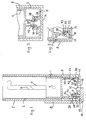
- a cup-shaped piston 1 which carries the cosmetic stick (not shown), is displaceable in a slotted sleeve 2, which in turn is rotatably received in a screw sleeve 5.
- the slit sleeve 2 has two diametrically opposite longitudinal slots 4.
- the piston 1 has on its outer wall two diametrically opposed, radially projecting pins 7 which protrude through the longitudinal slots 4 of the slot sleeve 2 into the respectively assigned thread 6 of the screw sleeve 5.
- the pin 7 are moved when rotating the screw sleeve 5 around the slotted sleeve 2 on the trailing edge of the threads 6 in the associated longitudinal slot 4, whereby the piston 1 is axially displaced in the slotted sleeve 2 and therefore the cosmetic stick from the open end of the Slotted sleeve 2 is withdrawn or retracted into slotted sleeve 2 until it reaches the starting position shown in FIG. 1.
- the slotted sleeve 2 with a cup-shaped foot part 3 with a central opening 19 in the bottom part bottom 17 extends beyond the screw sleeve 5, whereby the slotted sleeve is rotated relative to the screw sleeve 5 by engaging it and on the foot part 3 can be.
- the outer diameter of the foot part 3 corresponds to that of the screw sleeve 5.
- the cosmetic pencil mechanism is used with the foot part 3 of the slotted sleeve 2 and the lower part of the screw sleeve 5 in an outer cap part 8 in the exemplary embodiment (other shapes of the same are also possible) in which the screw sleeve can be rotated is, but the foot part 3 is held axially and against rotation.
- the outer cap part 8 on the inside of its cap bottom part 16 has a central hollow cylindrical extension 35 which projects through a central opening 19 in the bottom 17 of the foot part 3 and is held in a frictionally locking manner at the boundary edge of the central opening 19.
- a hollow cylindrical skirt 30 is formed as the first locking member, which extends in the starting position of the piston 1 to close to the bottom 17 of the foot part 3 and at a distance above the foot part bottom 17 has a locking opening 34 designed as an axial slot, the latter of which Piston 1 facing edge forms a locking shoulder 38 facing the piston.
- a resilient tab 31 is formed on the inside of the bottom 17 of the foot part 3 as a second locking member, which projects obliquely upwards and radially outwards towards the apron 30 and at its free end a radially outwards has locking lug 42 extending into the locking opening 34.
- the outer cap part 8 has an unlocking projection 32 on the inside of its bottom part 16, radially at a distance from its peripheral wall, which protrudes axially into the outer cap part 8.
- an opening 41 corresponding to the unlocking projection 32 is formed under the locking tab 31.
- two resilient locking tabs 30 are formed as locking members on the underside of the piston 1, which project axially downward from the piston in the undeformed state.
- Each of the locking tabs 30 has at its lower end a radially outwardly projecting shoulder, from the top of which the locking shoulder 38 is formed, which in the undeformed state of the tabs 30 lies at least approximately in a radial plane of the foot part 3.
- the other locking member on the foot part 3 is designed as a central hollow cylindrical locking projection 33 which projects upwards from the bottom 17 of the foot part 3 and forms a radially inwardly projecting ring collar at the upper end, from the underside of which the counter shoulder 39 is formed.
- the locking tabs 30 engage with their locking shoulders 38 under the counter shoulder 39 of the collar, so that the piston 1 is held locked in its starting position.
- the outer cap part 8 has on its bottom part 16 an unlocking projection 37 which, in the embodiment, is designed as a hollow cylindrical socket, but which can also be formed, for example, from individual, possibly resilient cylinder segments.
- the unlocking projection 37 engages between the bevelled side surfaces of the locking projections of the locking tabs 30 and the inside of the locking projection 33, as a result of which the locking projections are pressed radially inward with elastic deformation of the tabs 30 and Lock shoulders 38 disengage from the counter shoulder 39.
- the locking projections of the tabs 30 are held on the inside of the unlocking projection 37 in the starting position of the piston 1.
- the unlocking projection 37 fits into the locking projection 33 with a slight frictional engagement and interacts with it to hold the cosmetic stick mechanism in the outer cap part 8.
- FIG. 3 there is also a locking tab 30 on the underside of the piston 1, the locking projection of which, however, does not point radially outwards as in the embodiment according to FIG. 2, but radially inwards and forms the locking shoulder 38 with its upper side.
- the foot part 3 is provided with a central, hollow cylindrical locking projection 33 which has at its free end a radially outwardly projecting ring collar, from the underside of which the counter shoulder 39 is formed.
- the outer cap part 8 has an unlocking projection 32, which consists of individual hollow cylinder segments and surrounds the hollow cylindrical locking projection 33 of the foot part 3 after the cosmetic pencil mechanism has been inserted.
- the unlocking projection 32 passes through corresponding openings 41 in the bottom wall 17 of the foot part 3 and lifts the locking tab 30 out of the engagement of its locking shoulder 38 with the counter shoulder 39 in a manner as described above for the embodiment from FIG. 2.
- a plug closure between the foot part 3 of the cosmetic pencil mechanism and the outer cap part 8 a screw closure or a rotary closure can also be provided.
- a unlocking projection 32 in the form of a cylindrical segment, which engages through an arcuate slot 41 and whose upper side acts as an inclined ramp for lifting the locking tab 31 out of the locking opening 34 by rotating the outer cap part relative to the foot part 3 whose insertion is formed in the outer cap part 3.
- the unlocking projection 32 can in this case be provided with an axially downward-facing shoulder surface on its side that leads in the direction of rotation, which shoulder surface has an upward-facing counter surface on the foot part 3, for example with the top of the foot part bottom 17, at the end of the slot 41 for axially locking the Outer cap part 8 cooperates on the foot part 3 in a position in which he has lifted the locking tab 31 out of the locking opening 34.
- the outer cap part 8 and the foot part 3 can be held apart in a spring-loaded manner in order to secure the bayonet catch in the closed position.
- their spring force acting on the unlocking projection 32 is sufficient to keep the outer cap part 8 and the foot part 3 pressed apart somewhat.
Landscapes
- Cosmetics (AREA)
- Containers And Packaging Bodies Having A Special Means To Remove Contents (AREA)
Claims (4)
- Support de bâton de cosmétique comprenant un piston (1) servant à porter le bâton de cosmétique, qui peut coulisser dans une douille fendue (2) qui peut tourner dans une douille taraudée (5) et présente une fente longitudinale (4) à travers laquelle un téton (7) du piston (1) pénètre jusque dans une rainure de taraudage de la douille taraudée (5), la douille fendue (2) dépassant de la douille taraudée (5) par une partie de pied (3) qui peut être introduite, en pouvant en être retirée aisément, dans une partie de coiffe extérieure (8) présentant une partie de fond et dont la douille taraudée (5) dépasse de son côté en pouvant tourner de telle façon que le piston (1) puisse coulisser dans la douille fendue (2) par rotation de la douille taraudée (5) par rapport à la partie de coiffe extérieure (8) dans un sens de rotation vers l'extrémité de la douille fendue (2) opposée à la partie de pied (3) et dans l'autre sens de rotation en retour vers la partie de pied (3),
caractérisé en ce que
le piston (1) et la partie de pied (3) peuvent être verrouillés l'un à l'autre dans la position initiale du piston au moyen de deux organes de verrouillage (30, 31; 30, 33) dont un organe de verrouillage (30) part du piston (1) vers le bas et présente un épaulement de verrouillage (38) dirigé vers le piston, et dont l'autre organe de verrouillage (31; 33) est formé sur la partie de pied (3) et présente un contre-épaulement (39) conjugué de l'épaulement de verrouillage (38), et en ce que les organes de verrouillage, dont l'un au moins peut être dévié élastiquement, sont maintenus élastiquement hors engagement l'un de l'autre dans la partie de coiffe extérieure (8) lorsque le piston (1) se trouve dans la position initiale par une saillie de déverrouillage (32; 37) qui part de la partie de fond (16) de la partie de coiffe (18) et s'engage dans la partie de pied (3). - Support de bâton de cosmétique selon la revendication 1, caractérisé en ce qu'au moins un des organes de verrouillage est en forme de languette (30, 31) pouvant être déviée élastiquement par la saillie de déverrouillage.
- Support de bâton de cosmétique selon la revendication 1 ou 2, caractérisé en ce que l'organe de verrouillage (31) présentant le contre-épaulement (39) est formé sur une saillie de verrouillage faisant saillie du fond (17) de la partie de pied (3) vers le piston (1), déviée élastiquement par la saillie de déverrouillage (37).
- Support de bâton de cosmétique selon l'une quelconque des revendications 1 à 3, caractérisé en ce que l'épaulement de verrouillage (38) ou le contre-épaulement est formé par la partie de bord opposée au piston (1) d'une ouverture de verrouillage (34).
Applications Claiming Priority (2)
| Application Number | Priority Date | Filing Date | Title |
|---|---|---|---|
| DE9207284U DE9207284U1 (de) | 1992-05-29 | 1992-05-29 | Kosmetikstifthalter |
| DE9207284U | 1992-05-29 |
Publications (2)
| Publication Number | Publication Date |
|---|---|
| EP0572013A1 EP0572013A1 (fr) | 1993-12-01 |
| EP0572013B1 true EP0572013B1 (fr) | 1997-02-12 |
Family
ID=6880018
Family Applications (1)
| Application Number | Title | Priority Date | Filing Date |
|---|---|---|---|
| EP93108598A Expired - Lifetime EP0572013B1 (fr) | 1992-05-29 | 1993-05-27 | Etui pour produits cosmétiques |
Country Status (2)
| Country | Link |
|---|---|
| EP (1) | EP0572013B1 (fr) |
| DE (2) | DE9207284U1 (fr) |
Families Citing this family (3)
| Publication number | Priority date | Publication date | Assignee | Title |
|---|---|---|---|---|
| DE19501213C2 (de) * | 1995-01-17 | 1997-06-12 | Henkel Kgaa | Vorrichtung zur Aufnahme und Abgabe eines streichfähigen Materials |
| GB2513462A (en) * | 2013-03-13 | 2014-10-29 | Toly Man Ltd | Cosmetic container |
| US11882916B2 (en) * | 2020-09-24 | 2024-01-30 | Hcp Packaging Usa, Inc. | Refillable cosmetic dispenser |
Citations (1)
| Publication number | Priority date | Publication date | Assignee | Title |
|---|---|---|---|---|
| GB853306A (en) * | 1956-06-14 | 1960-11-02 | Artistic Containers Ltd | Improvements relating to containers for lipsticks and like cosmetics |
Family Cites Families (4)
| Publication number | Priority date | Publication date | Assignee | Title |
|---|---|---|---|---|
| NL100510C (fr) * | 1953-03-23 | |||
| GB1163542A (en) * | 1965-08-31 | 1969-09-10 | Sebec | Lipstick containers |
| GB1280635A (en) * | 1968-11-08 | 1972-07-05 | Sebec | Lipstick and like containers |
| KR910014077A (ko) * | 1990-01-19 | 1991-08-31 | 쉬지니 끌로드 | 동심원상으로 배치된 2개의 회전부재사이의 회전마찰장치 |
-
1992
- 1992-05-29 DE DE9207284U patent/DE9207284U1/de not_active Expired - Lifetime
-
1993
- 1993-05-27 EP EP93108598A patent/EP0572013B1/fr not_active Expired - Lifetime
- 1993-05-27 DE DE59305431T patent/DE59305431D1/de not_active Expired - Fee Related
Patent Citations (1)
| Publication number | Priority date | Publication date | Assignee | Title |
|---|---|---|---|---|
| GB853306A (en) * | 1956-06-14 | 1960-11-02 | Artistic Containers Ltd | Improvements relating to containers for lipsticks and like cosmetics |
Also Published As
| Publication number | Publication date |
|---|---|
| DE59305431D1 (de) | 1997-03-27 |
| DE9207284U1 (de) | 1993-09-23 |
| EP0572013A1 (fr) | 1993-12-01 |
Similar Documents
| Publication | Publication Date | Title |
|---|---|---|
| DE69607260T2 (de) | Befestigungsring mit Doppelindexiervorrichtung | |
| DE2734312C2 (fr) | ||
| DE68902980T2 (de) | Behaelter und verschlusskappe mit oder ohne kindersicherung. | |
| DE10332297B4 (de) | Gehäuse | |
| DE2200044A1 (de) | Loesbare Befestigungsvorrichtung | |
| DE3843095C2 (de) | Befestigungseinrichtung für Verkleidungen | |
| DE2016387C3 (de) | Schutz- und Entnahmebehälter für einen Stift aus pastenförmigem Material | |
| DE3544630A1 (de) | Drehbarer behaelter fuer lippenpomade | |
| EP0021047A1 (fr) | Trépied pour écrans de projection | |
| DE102019107890A1 (de) | Vorrichtung zum Auftragen einer abtragbaren Masse in Form eines Stiftes | |
| DE1665786B1 (de) | Druckknopfvorsatzgeraet fuer elektrische Druckknopfschalter | |
| EP0572013B1 (fr) | Etui pour produits cosmétiques | |
| EP0554497A1 (fr) | Support pour bâton de cosmétique | |
| DE112010005613T5 (de) | Rohrförmiges Gehäuse | |
| EP3982787B1 (fr) | Dispositif de distribution d'une masse | |
| EP0230259A2 (fr) | Boîtier en forme de parallélépipède pour objets | |
| DE3735912A1 (de) | Nachgiebig befestigter veraenderbarer widerstand | |
| EP0554496B1 (fr) | Support pour bâton de cosmétique | |
| DE2248281C3 (de) | Halter für einen Stift aus einem pastenartigen Material | |
| DE3516093C2 (fr) | ||
| DE3129851A1 (de) | Mehrteiliger moebelfuss aus kunststoff | |
| EP0185748B1 (fr) | Recipient pour cosmetiques en baton, en particulier pour des batons de rouge a levres | |
| DE4206299C2 (de) | Stiftträger mit auswechselbarer Stifteinheit | |
| DE1586560B1 (de) | Behaelter insbesondere fuer eine band oder filmspule | |
| DE69502226T2 (de) | Markiervorrichtung mit einem bewegbaren indexierbaren Einsatz für Spritzgiessform |
Legal Events
| Date | Code | Title | Description |
|---|---|---|---|
| PUAI | Public reference made under article 153(3) epc to a published international application that has entered the european phase |
Free format text: ORIGINAL CODE: 0009012 |
|
| AK | Designated contracting states |
Kind code of ref document: A1 Designated state(s): DE FR GB |
|
| 17P | Request for examination filed |
Effective date: 19940531 |
|
| RAP1 | Party data changed (applicant data changed or rights of an application transferred) |
Owner name: WILCO CONSULTANTS LIMITED |
|
| GRAG | Despatch of communication of intention to grant |
Free format text: ORIGINAL CODE: EPIDOS AGRA |
|
| GRAG | Despatch of communication of intention to grant |
Free format text: ORIGINAL CODE: EPIDOS AGRA |
|
| 17Q | First examination report despatched |
Effective date: 19960315 |
|
| GRAH | Despatch of communication of intention to grant a patent |
Free format text: ORIGINAL CODE: EPIDOS IGRA |
|
| GRAH | Despatch of communication of intention to grant a patent |
Free format text: ORIGINAL CODE: EPIDOS IGRA |
|
| GRAA | (expected) grant |
Free format text: ORIGINAL CODE: 0009210 |
|
| AK | Designated contracting states |
Kind code of ref document: B1 Designated state(s): DE FR GB |
|
| PG25 | Lapsed in a contracting state [announced via postgrant information from national office to epo] |
Ref country code: GB Effective date: 19970212 Ref country code: FR Effective date: 19970212 |
|
| REF | Corresponds to: |
Ref document number: 59305431 Country of ref document: DE Date of ref document: 19970327 |
|
| EN | Fr: translation not filed | ||
| GBV | Gb: ep patent (uk) treated as always having been void in accordance with gb section 77(7)/1977 [no translation filed] |
Effective date: 19970212 |
|
| PLBE | No opposition filed within time limit |
Free format text: ORIGINAL CODE: 0009261 |
|
| 26N | No opposition filed | ||
| PGFP | Annual fee paid to national office [announced via postgrant information from national office to epo] |
Ref country code: DE Payment date: 19980730 Year of fee payment: 6 |
|
| PG25 | Lapsed in a contracting state [announced via postgrant information from national office to epo] |
Ref country code: DE Free format text: LAPSE BECAUSE OF NON-PAYMENT OF DUE FEES Effective date: 20000301 |