EP0572013B1 - Apparatus for applying cosmetic preparations - Google Patents
Apparatus for applying cosmetic preparations Download PDFInfo
- Publication number
- EP0572013B1 EP0572013B1 EP93108598A EP93108598A EP0572013B1 EP 0572013 B1 EP0572013 B1 EP 0572013B1 EP 93108598 A EP93108598 A EP 93108598A EP 93108598 A EP93108598 A EP 93108598A EP 0572013 B1 EP0572013 B1 EP 0572013B1
- Authority
- EP
- European Patent Office
- Prior art keywords
- piston
- locking
- outer cap
- sleeve
- foot part
- Prior art date
- Legal status (The legal status is an assumption and is not a legal conclusion. Google has not performed a legal analysis and makes no representation as to the accuracy of the status listed.)
- Expired - Lifetime
Links
Images
Classifications
-
- A—HUMAN NECESSITIES
- A45—HAND OR TRAVELLING ARTICLES
- A45D—HAIRDRESSING OR SHAVING EQUIPMENT; EQUIPMENT FOR COSMETICS OR COSMETIC TREATMENTS, e.g. FOR MANICURING OR PEDICURING
- A45D40/00—Casings or accessories specially adapted for storing or handling solid or pasty toiletry or cosmetic substances, e.g. shaving soaps or lipsticks
- A45D40/06—Casings wherein movement of the lipstick or like solid is a screwing movement
Definitions
- the invention relates to a cosmetic pencil holder with a piston for carrying the cosmetic pencil, which is displaceable in a slotted sleeve, which is rotatable in a screw sleeve and has a longitudinal slot, through which a pin on the piston extends into a thread in the screw sleeve, whereby the slotted sleeve protrudes with a foot part from the screw sleeve, which can be easily detachably inserted into an outer cap part having a bottom part, from which the screw sleeve in turn protrudes, in such a way that the piston in the slotted sleeve rotates relative to the outer cap part in one direction of rotation by rotating the screw sleeve the end of the slotted sleeve facing away from the foot part, and in the other direction of rotation back to the foot part can be displaced into an initial position.
- a holder is known from GB-A-853 306.
- the cosmetic stick which can be supported with its foot on the cup-shaped piston, for example, which can be a lipstick, a deodorant stick or the like, is moved out of the open end of the slotted sleeve or back into inserted the slotted sleeve.
- the outer cap part serves as the lower part of a protective cover, which is usually designed as a decorative cover.
- cosmetic pen mechanism an easily releasable closure between the outer cap part and the assembly fastened in this, which is also referred to as "cosmetic pen mechanism"
- cosmetic pen mechanism so that the outer cap part can be designed as a relatively valuable piece of jewelry and after the cosmetic pen has been used with another cosmetic pen mechanism can be reused with a new cosmetic pencil.
- cosmetic pencil mechanics are manufactured and sold as replacement assemblies.
- the cosmetic stick can also be moved out of the slotted sleeve outside the outer cap part by rotating the screw sleeve relative to the foot part protruding therefrom. so that in many cases it is not guaranteed for buyers that the purchased cosmetic stick is unused.
- the invention solves the problem of designing a cosmetic pencil holder of the type mentioned in the preamble of claim 1 in such a way that the cosmetic pencil mechanism outside of the outer cap part is largely inoperative for extending the cosmetic pencil, but is functional within the outer cap part.
- the piston and the foot part can be locked to one another in the starting position of the piston by means of two locking members, of which one locking member protrudes downward from the piston and has a locking shoulder facing the piston, and of which the other locking member is formed on the foot part and has a counter shoulder assigned to the locking shoulder.
- the locking members at least one of which is resiliently deflectable, are, however, resiliently held in the outer cap part when the piston is in the starting position by an unlocking projection which preferably projects freely from the bottom part of the outer cap part and engages axially from below in the foot part.
- the piston is locked in the starting position of the piston against its axial displacement in the slot sleeve via the counter shoulder on the foot part, from which the locking shoulder on the locking member formed on the piston is overlapped.
- the screw sleeve and the slotted sleeve are also locked against relative rotation via the pin of the piston engaging in the thread of the screw sleeve.
- the easily releasable closure between the outer cap part and the foot part of the cosmetic pen mechanism can be a plug closure which is produced by axially pushing the outer cap part onto the foot part.
- the unlocking projection moves axially between the locking members in the foot part.
- the locking member having the locking shoulder is designed as a spring deflected by the unlocking projection, and the deflection of the tab is reversed when it slides off the unlocking projection while the cosmetic stick is being extended, appropriate inclined surfaces can be used to ensure that the tab when returning the Piston is more easily deflected back into the starting position and the start of the tab against the unlocking projection. It is also possible to design both locking members as tabs which are resiliently deflected by the unlocking projection. However, the locking member having the locking shoulder on the piston is preferably not deflected by the unlocking projection, so that it maintains its relative position to the piston during the piston movements.
- the locking member having the counter shoulder is designed to be resiliently deflectable from the unlocking projection when the cosmetic pencil mechanism is inserted into the outer cap part, be it as a resilient tab formed on or in the peripheral wall of the foot part, whether as a tab protruding from the bottom part of the foot part or as a protruding part differently trained lead.
- the locking shoulder and / or the counter shoulder can be formed on lateral projections of the locking members.
- the locking shoulder or the counter shoulder can be formed from the edge part of an opening facing away from the piston in the relevant locking element.
- the other locking member has a lateral projection which engages in the opening when the cosmetic pen mechanism is located outside the outer cap part and is lifted out of the opening by the unlocking projection when the cosmetic pin mechanism is inserted into the outer cap part.
- a cup-shaped piston 1 which carries the cosmetic stick (not shown), is displaceable in a slotted sleeve 2, which in turn is rotatably received in a screw sleeve 5.
- the slit sleeve 2 has two diametrically opposite longitudinal slots 4.
- the piston 1 has on its outer wall two diametrically opposed, radially projecting pins 7 which protrude through the longitudinal slots 4 of the slot sleeve 2 into the respectively assigned thread 6 of the screw sleeve 5.
- the pin 7 are moved when rotating the screw sleeve 5 around the slotted sleeve 2 on the trailing edge of the threads 6 in the associated longitudinal slot 4, whereby the piston 1 is axially displaced in the slotted sleeve 2 and therefore the cosmetic stick from the open end of the Slotted sleeve 2 is withdrawn or retracted into slotted sleeve 2 until it reaches the starting position shown in FIG. 1.
- the slotted sleeve 2 with a cup-shaped foot part 3 with a central opening 19 in the bottom part bottom 17 extends beyond the screw sleeve 5, whereby the slotted sleeve is rotated relative to the screw sleeve 5 by engaging it and on the foot part 3 can be.
- the outer diameter of the foot part 3 corresponds to that of the screw sleeve 5.
- the cosmetic pencil mechanism is used with the foot part 3 of the slotted sleeve 2 and the lower part of the screw sleeve 5 in an outer cap part 8 in the exemplary embodiment (other shapes of the same are also possible) in which the screw sleeve can be rotated is, but the foot part 3 is held axially and against rotation.
- the outer cap part 8 on the inside of its cap bottom part 16 has a central hollow cylindrical extension 35 which projects through a central opening 19 in the bottom 17 of the foot part 3 and is held in a frictionally locking manner at the boundary edge of the central opening 19.
- a hollow cylindrical skirt 30 is formed as the first locking member, which extends in the starting position of the piston 1 to close to the bottom 17 of the foot part 3 and at a distance above the foot part bottom 17 has a locking opening 34 designed as an axial slot, the latter of which Piston 1 facing edge forms a locking shoulder 38 facing the piston.
- a resilient tab 31 is formed on the inside of the bottom 17 of the foot part 3 as a second locking member, which projects obliquely upwards and radially outwards towards the apron 30 and at its free end a radially outwards has locking lug 42 extending into the locking opening 34.
- the outer cap part 8 has an unlocking projection 32 on the inside of its bottom part 16, radially at a distance from its peripheral wall, which protrudes axially into the outer cap part 8.
- an opening 41 corresponding to the unlocking projection 32 is formed under the locking tab 31.
- two resilient locking tabs 30 are formed as locking members on the underside of the piston 1, which project axially downward from the piston in the undeformed state.
- Each of the locking tabs 30 has at its lower end a radially outwardly projecting shoulder, from the top of which the locking shoulder 38 is formed, which in the undeformed state of the tabs 30 lies at least approximately in a radial plane of the foot part 3.
- the other locking member on the foot part 3 is designed as a central hollow cylindrical locking projection 33 which projects upwards from the bottom 17 of the foot part 3 and forms a radially inwardly projecting ring collar at the upper end, from the underside of which the counter shoulder 39 is formed.
- the locking tabs 30 engage with their locking shoulders 38 under the counter shoulder 39 of the collar, so that the piston 1 is held locked in its starting position.
- the outer cap part 8 has on its bottom part 16 an unlocking projection 37 which, in the embodiment, is designed as a hollow cylindrical socket, but which can also be formed, for example, from individual, possibly resilient cylinder segments.
- the unlocking projection 37 engages between the bevelled side surfaces of the locking projections of the locking tabs 30 and the inside of the locking projection 33, as a result of which the locking projections are pressed radially inward with elastic deformation of the tabs 30 and Lock shoulders 38 disengage from the counter shoulder 39.
- the locking projections of the tabs 30 are held on the inside of the unlocking projection 37 in the starting position of the piston 1.
- the unlocking projection 37 fits into the locking projection 33 with a slight frictional engagement and interacts with it to hold the cosmetic stick mechanism in the outer cap part 8.
- FIG. 3 there is also a locking tab 30 on the underside of the piston 1, the locking projection of which, however, does not point radially outwards as in the embodiment according to FIG. 2, but radially inwards and forms the locking shoulder 38 with its upper side.
- the foot part 3 is provided with a central, hollow cylindrical locking projection 33 which has at its free end a radially outwardly projecting ring collar, from the underside of which the counter shoulder 39 is formed.
- the outer cap part 8 has an unlocking projection 32, which consists of individual hollow cylinder segments and surrounds the hollow cylindrical locking projection 33 of the foot part 3 after the cosmetic pencil mechanism has been inserted.
- the unlocking projection 32 passes through corresponding openings 41 in the bottom wall 17 of the foot part 3 and lifts the locking tab 30 out of the engagement of its locking shoulder 38 with the counter shoulder 39 in a manner as described above for the embodiment from FIG. 2.
- a plug closure between the foot part 3 of the cosmetic pencil mechanism and the outer cap part 8 a screw closure or a rotary closure can also be provided.
- a unlocking projection 32 in the form of a cylindrical segment, which engages through an arcuate slot 41 and whose upper side acts as an inclined ramp for lifting the locking tab 31 out of the locking opening 34 by rotating the outer cap part relative to the foot part 3 whose insertion is formed in the outer cap part 3.
- the unlocking projection 32 can in this case be provided with an axially downward-facing shoulder surface on its side that leads in the direction of rotation, which shoulder surface has an upward-facing counter surface on the foot part 3, for example with the top of the foot part bottom 17, at the end of the slot 41 for axially locking the Outer cap part 8 cooperates on the foot part 3 in a position in which he has lifted the locking tab 31 out of the locking opening 34.
- the outer cap part 8 and the foot part 3 can be held apart in a spring-loaded manner in order to secure the bayonet catch in the closed position.
- their spring force acting on the unlocking projection 32 is sufficient to keep the outer cap part 8 and the foot part 3 pressed apart somewhat.
Landscapes
- Cosmetics (AREA)
- Containers And Packaging Bodies Having A Special Means To Remove Contents (AREA)
Description
Die Erfindung betrifft einen Kosmetikstifthalter mit einem zum Tragen des Kosmetikstiftes dienenden Kolben, der in einer Schlitzhülse verschiebbar ist, die in einer Schraubhülse drehbar ist und einen Längsschlitz aufweist, durch den hindurch ein Zapfen an dem Kolben bis in einen Gewindegang in der Schraubhülse ragt, wobei die Schlitzhülse mit einem Fußteil aus der Schraubhülse herausragt, das leicht lösbar in einen einen Bodenteil aufweisenden Außenkappenteil einsetzbar ist, aus dem die Schraubhülse ihrerseits drehbar vorsteht, derart, daß der Kolben in der Schlitzhülse durch Drehen der Schraubhülse relativ zum Außenkappenteil in der einen Drehrichtung zu dem dem Fußteil abgewandten Ende der Schlitzhülse hin, und in der anderen Drehrichtung zurück zu dem Fußteil hin bis in eine Ausgangsstellung verschiebbar ist. Ein derartiger Halter ist aus GB-A-853 306 bekannt.The invention relates to a cosmetic pencil holder with a piston for carrying the cosmetic pencil, which is displaceable in a slotted sleeve, which is rotatable in a screw sleeve and has a longitudinal slot, through which a pin on the piston extends into a thread in the screw sleeve, whereby the slotted sleeve protrudes with a foot part from the screw sleeve, which can be easily detachably inserted into an outer cap part having a bottom part, from which the screw sleeve in turn protrudes, in such a way that the piston in the slotted sleeve rotates relative to the outer cap part in one direction of rotation by rotating the screw sleeve the end of the slotted sleeve facing away from the foot part, and in the other direction of rotation back to the foot part can be displaced into an initial position. Such a holder is known from GB-A-853 306.
Durch eine solche Verschiebung des Kolbens beim Drehen der Schraubhülse relativ zu dem Außenkappenteil wird der mit seinem Fuß an dem z.B. becherförmigen Kolben abgestützte Kosmetikstift, der ein Lippenstift, ein Deodorantstift oder dergl. sein kann, aus dem offenen Ende der Schlitzhülse herausgefahren bzw. wieder in die Schlitzhülse hineingefahren. Der Außenkappenteil dient als unterer Teil einer Schutzhülle, die zumeist als Dekorhülle ausgeführt ist. Hierbei ist es bekannt, zwischen dem Außenkappenteil und der in dieser befestigten Baugruppe, die auch mit "Kosmetikstiftmechanik" bezeichnet wird, einen leicht lösbaren Verschluß vorzusehen, so daß der Außenkappenteil als relativ wertvolles Schmuckstück ausgeführt sein und nach dem Verbrauch des Kosmetikstiftes mit einer anderen Kosmetikstiftmechanik mit einem neuen Kosmetikstift wiederverwendet werden kann. Hierzu werden Kosmetikstiftmechaniken als Austauschbaugruppen hergestellt und vertrieben. Jedoch kann bei solchen Austauschbaugruppen außerhalb des Außenkappenteils der Kosmetikstift auch dadurch aus der Schlitzhülse ausgefahren werden, daß die Schraubhülse relativ zu dem aus dieser herausstehenden Fußteil gedreht wird, so daß für die Käufer in etlichen Fällen nicht gewährleistet ist, daß der eingekaufte Kosmetikstift unbenutzt ist.Through such a displacement of the piston when the screw sleeve is rotated relative to the outer cap part, the cosmetic stick, which can be supported with its foot on the cup-shaped piston, for example, which can be a lipstick, a deodorant stick or the like, is moved out of the open end of the slotted sleeve or back into inserted the slotted sleeve. The outer cap part serves as the lower part of a protective cover, which is usually designed as a decorative cover. Here, it is known to provide an easily releasable closure between the outer cap part and the assembly fastened in this, which is also referred to as "cosmetic pen mechanism", so that the outer cap part can be designed as a relatively valuable piece of jewelry and after the cosmetic pen has been used with another cosmetic pen mechanism can be reused with a new cosmetic pencil. For this purpose cosmetic pencil mechanics are manufactured and sold as replacement assemblies. However, in the case of such replacement assemblies, the cosmetic stick can also be moved out of the slotted sleeve outside the outer cap part by rotating the screw sleeve relative to the foot part protruding therefrom. so that in many cases it is not guaranteed for buyers that the purchased cosmetic stick is unused.
Durch die Erfindung wird das Problem gelöst, einen Kosmetikstifthalter der im Oberbegriff des Anspruchs 1 genannten Art so zu gestalten, daß die Kosmetikstiftmechanik außerhalb des Außenkappenteils für ein Ausfahren des Kosmetikstiftes weitgehend funktionsuntüchtig, jedoch innerhalb des Außenkappenteils funktionstüchtig ist.The invention solves the problem of designing a cosmetic pencil holder of the type mentioned in the preamble of claim 1 in such a way that the cosmetic pencil mechanism outside of the outer cap part is largely inoperative for extending the cosmetic pencil, but is functional within the outer cap part.
Gemäß der Erfindung sind der Kolben und der Fußteil in der Ausgangsstellung des Kolbens mittels zweier Verriegelungsglieder aneinander verriegelbar, von denen das eine Verriegelungsglied von dem Kolben nach unten absteht und eine dem Kolben zugewandte Verriegelungsschulter aufweist, und von denen das andere Verriegelungsglied an dem Fußteil ausgebildet ist und eine der Verriegelungsschulter zugeordnete Gegenschulter aufweist. Die Verriegelungsglieder, von denen wenigstens eines federnd auslenkbar ist, sind jedoch in dem Außenkappenteil bei in der Ausgangsstellung befindlichem Kolben von einem Entriegelungsvorsprung, der von dem Bodenteil des Außenkappenteils vorzugsweise frei absteht und in den Fußteil axial von unten eingreift, federnd außer Eingriff miteinander gehalten.According to the invention, the piston and the foot part can be locked to one another in the starting position of the piston by means of two locking members, of which one locking member protrudes downward from the piston and has a locking shoulder facing the piston, and of which the other locking member is formed on the foot part and has a counter shoulder assigned to the locking shoulder. The locking members, at least one of which is resiliently deflectable, are, however, resiliently held in the outer cap part when the piston is in the starting position by an unlocking projection which preferably projects freely from the bottom part of the outer cap part and engages axially from below in the foot part.
Wenn sich daher die Kosmetikstiftmechanik außerhalb des Außenkappenteils befindet, ist der Kolben über die Gegenschulter am Fußteil, von der die Verriegelungsschulter an dem am Kolben ausgebildeten Verriegelungsglied übergriffen wird, in der Ausgangsstellung des Kolbens gegen dessen Axialverschiebung in der Schlitzhülse verriegelt. Hierdurch sind über den in den Gewindegang der Schraubhülse eingreifenden Zapfen des Kolbens auch die Schraubhülse und die Schlitzhülse gegen eine Relativdrehung gesperrt. Durch die Montage der Kosmetikstiftmechanik in dem Außenkappenteil hingegen greift der Entriegelungsvorsprung am Bodenteil des Außenkappenteils zwischen die Verriegelungsglieder ein und drückt sie radial auseinander und löst damit die Verriegelung. Hierdurch kann die Gegenschulter von der Verriegelungsschulter beim Drehen des Außenkappenteils relativ zu der Schraubhülse für das Ausfahren des Kolbens und damit des Kosmetikstiftes passiert werden.Therefore, if the cosmetic pen mechanism is located outside the outer cap part, the piston is locked in the starting position of the piston against its axial displacement in the slot sleeve via the counter shoulder on the foot part, from which the locking shoulder on the locking member formed on the piston is overlapped. As a result, the screw sleeve and the slotted sleeve are also locked against relative rotation via the pin of the piston engaging in the thread of the screw sleeve. By mounting the cosmetic pen mechanism in the outer cap part, however, the unlocking protrusion on the bottom part of the outer cap part engages between the locking members and presses them apart radially, thereby releasing the locking. This allows the Counter shoulder should be passed from the locking shoulder when rotating the outer cap part relative to the screw sleeve for extending the piston and thus the cosmetic stick.
Der leicht lösbare Verschluß zwischen dem Außenkappenteil und dem Fußteil der Kosmetikstiftmechanik kann ein Steckverschluß sein, der durch axiales Aufstecken des Außenkappenteils auf den Fußteil hergestellt wird. Bei einer solchen Ausführungsform fährt der Entriegelungsvorsprung axial zwischen die Verriegelungsglieder in dem Fußteil ein. Es ist jedoch auch möglich, den leicht lösbaren Verschluß durch eine Relativdrehung oder eine schraubende Relativbewegung herzustellen, so daß dann der Entriegelungsvorsprung zwischen die Verriegelungsglieder hineingedreht wird.The easily releasable closure between the outer cap part and the foot part of the cosmetic pen mechanism can be a plug closure which is produced by axially pushing the outer cap part onto the foot part. In such an embodiment, the unlocking projection moves axially between the locking members in the foot part. However, it is also possible to produce the easily releasable closure by a relative rotation or a screwing relative movement, so that the unlocking projection is then screwed in between the locking members.
Wenn das die Verriegelungsschulter aufweisende Verriegelungsglied als von dem Entriegelungsvorsprung federnd ausgelenkte Lasche ausgebildet ist, und die Auslenkung der Lasche bei deren Abgleiten von dem Entriegelungsvorsprung während des Ausfahrens des Kosmetikstiftes rückgängig gemacht wird, kann durch entsprechende Schrägflächen dafür gesorgt werden, daß die Lasche beim Zurückkehren des Kolbens in die Ausgangsstellung und dem Anlaufen der Lasche gegen den Entriegelungsvorsprung leichter wieder ausgelenkt wird. Es ist auch möglich, beide Verriegelungsglieder als von dem Entriegelungsvorsprung federnd ausgelenkte Laschen auszubilden. Bevorzugt wird jedoch das die Verriegelungsschulter aufweisende Verriegelungsglied an dem Kolben von dem Entriegelungsvorsprung nicht ausgelenkt, so daß es seine Relativlage zum Kolben während der Kolbenbewegungen beibehält. In diesem Fall ist daher das die Gegenschulter aufweisende Verriegelungsglied von dem Entriegelungsvorsprung beim Einsetzen der Kosmetikstiftmechanik in den Außenkappenteil federnd auslenkbar gestaltet, sei es als an oder in der Umfangswand des Fußteils angeformte federnde Lasche, sei es als von dem Bodenteil des Fußteils abstehende Lasche oder abstehender anders ausgebildeter Vorsprung.If the locking member having the locking shoulder is designed as a spring deflected by the unlocking projection, and the deflection of the tab is reversed when it slides off the unlocking projection while the cosmetic stick is being extended, appropriate inclined surfaces can be used to ensure that the tab when returning the Piston is more easily deflected back into the starting position and the start of the tab against the unlocking projection. It is also possible to design both locking members as tabs which are resiliently deflected by the unlocking projection. However, the locking member having the locking shoulder on the piston is preferably not deflected by the unlocking projection, so that it maintains its relative position to the piston during the piston movements. In this case, therefore, the locking member having the counter shoulder is designed to be resiliently deflectable from the unlocking projection when the cosmetic pencil mechanism is inserted into the outer cap part, be it as a resilient tab formed on or in the peripheral wall of the foot part, whether as a tab protruding from the bottom part of the foot part or as a protruding part differently trained lead.
Die Verriegelungsschulter und/oder die Gegenschulter können an seitlichen Vorsprüngen der Verriegelungsglieder ausgebildet sein. Es ist jedoch auch möglich, daß die Verriegelungsschulter oder die Gegenschulter von dem dem Kolben abgewandten Randteil einer Öffnung in dem betreffenden einen Verriegelungsglied ausgebildet ist. Bei dieser Ausführungsform weist das andere Verriegelungsglied einen seitlichen Vorsprung auf, der bei außerhalb des Außenkappenteils befindlicher Kosmetikstiftmechanik in die Öffnung eingreift und beim Einsetzen der Kosmetikstiftmechanik in das Außenkappenteil von dem Entriegelungsvorsprung entriegelnd aus der Öffnung ausgehoben wird.The locking shoulder and / or the counter shoulder can be formed on lateral projections of the locking members. However, it is also possible for the locking shoulder or the counter shoulder to be formed from the edge part of an opening facing away from the piston in the relevant locking element. In this embodiment, the other locking member has a lateral projection which engages in the opening when the cosmetic pen mechanism is located outside the outer cap part and is lifted out of the opening by the unlocking projection when the cosmetic pin mechanism is inserted into the outer cap part.
Die Erfindung wird anhand von Ausführungsformen erläutert, die schematisch aus der Zeichnung ersichtlich sind. In der Zeichnung zeigt:
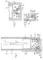
- Fig. 1 einen erfindungsgemäßen Kosmetikstifthalter im Längsschnitt, wobei in der linken Hälfte der Figur die Kosmetikstiftmechanik in einen Außenkappenteil eingesetzt gezeigt ist, und in der rechten Hälfte der Figur die Kosmetikstiftmechanik außerhalb des Außenkappenteils dargestellt ist,
- Fig. 2 eine zweite Ausführungsform eines erfindungsgemäßen Kosmetikstifthalters im Bereich des Fußteils im Teillängsschnitt, und
- Fig. 3 eine dritte Ausführungsform eines erfindungsgemäßen Kosmetikstifthalters im Teillängsschnitt.
- 1 shows a cosmetic pencil holder according to the invention in longitudinal section, the cosmetic pencil mechanism being shown inserted into an outer cap part in the left half of the figure, and the cosmetic pencil mechanism being shown outside the outer cap part in the right half of the figure,
- Fig. 2 shows a second embodiment of a cosmetic pencil holder according to the invention in the region of the foot part in the partial longitudinal section, and
- Fig. 3 shows a third embodiment of a cosmetic pencil holder according to the invention in partial longitudinal section.
Wie insbesondere aus Figur 1 der Zeichnung ersichtlich, ist ein becherförmiger Kolben 1, der den Kosmetikstift (nicht gezeigt) trägt, in einer Schlitzhülse 2 verschiebbar, die ihrerseits in einer Schraubhülse 5 drehbar aufgenommen ist. Die Schlitzhülse 2 weist zwei einander diametral gegenüberliegende Längsschlitze 4 auf. In der Innenwandung der Schraubhülse 5 sind zwei einander gegenüberliegende Gewindegänge 6 mit relativ großer Steigung ausgebildet. Der Kolben 1 weist an seiner Außenwandung zwei einander diametral gegenüberliegende, radial abstehende Zapfen 7 auf, die durch die Längsschlitze 4 der Schlitzhülse 2 bis in den jeweils zugeordneten Gewindegang 6 der Schraubhülse 5 ragen. Daher werden die Zapfen 7 bei Drehen der der Schraubhülse 5 um die Schlitzhülse 2 an dem dabei nachlaufenden Rand der Gewindegänge 6 in dem zugeordneten Längsschlitz 4 verschoben, wodurch der Kolben 1 in der Schlitzhülse 2 axial verlagert wird und daher der Kosmetikstift aus dem offenen Ende der Schlitzhülse 2 herausgefahren bzw. in die Schlitzhülse 2 bis in seine in Fig. 1 gezeigte Ausgangsstellung zurückgefahren wird.As can be seen in particular from FIG. 1 of the drawing, a cup-shaped piston 1, which carries the cosmetic stick (not shown), is displaceable in a slotted
In den in den Fig. 1 bis 3 gezeigten Ausführungsformen ragt die Schlitzhülse 2 mit einem becherförmigen Fußteil 3 mit einer Zentralöffnung 19 im Fußteilboden 17 über die Schraubhülse 5 hinaus, wodurch die Schlitzhülse relativ zur Schraubhülse 5 durch Angreifen an dieser und an dem Fußteil 3 gedreht werden kann. Der Außendurchmesser des Fußteils 3 entspricht dem der Schraubhülse 5. Die Kosmetikstiftmechanik ist mit dem Fußteil 3 der Schlitzhülse 2 und dem unteren Teil der Schraubhülse 5 in ein im Ausführungsbeispiel zylindertopfförmiges Außenkappenteil 8 (andere Formen desselben sind ebenfalls möglich) eingesetzt, in dem die Schraubhülse drehbar ist, das Fußteil 3 jedoch axial und gegen Drehung gehalten ist. Hierzu weist bei der Ausführungsform aus Fig. 1 das Außenkappenteil 8 an der Innenseite seines Kappenbodenteils 16 einen zentralen hohlzylindrischen Ansatz 35 auf, der durch eine Zentralöffnung 19 im Boden 17 des Fußteils 3 ragt und reibschlüssig am Begrenzungsrand der Zentralöffnung 19 gehalten ist.In the embodiments shown in FIGS. 1 to 3, the
Bei nicht in das Außenkappenteil 8 eingesetzter Kosmetikstiftmechanik ist bei allen dargestellten Ausführungsformen der Kolben 1 in seiner in Fig. 1 gezeigten Ausgangsstellung gegen ein Ausfahren des Kosmetikstiftes aus der Schlitzhülse 2 axial verriegelt, wodurch auch die Schraubhülse 5 und die Schlitzhülse 2 gegen eine Relativdrehung verriegelt sind. Diese Verriegelung wird jedoch durch das Einsetzen der Kosmetikstiftmechanik mit dem Fußteil 3 ihrer Schlitzhülse 2 in das Außenkappenteil 8 selbsttätig gelöst. Der Verriegelungszustand für den Kosmetikstifthalter nach Fig. 1 ist dort in der rechten Figurenhälfte gezeigt, in welcher das Außenkappenteil 8 fehlt. An der Unterseite des Kolbens 1 ist als erstes Verriegelungsglied eine hohlzylindrische Schürze 30 angeformt, die in der Ausgangsstellung des Kolbens 1 bis nahe zum Boden 17 des Fußteils 3 reicht und im Abstand über dem Fußteilboden 17 eine als axiales Langloch ausgebildete Verriegelungsöffnung 34 aufweist, deren dem Kolben 1 abgewandter Randteil eine dem Kolben zugewandte Verriegelungsschulter 38 bildet. Radial im Abstand von und innerhalb der Schürze 30 ist an der Innenseite des Bodens 17 des Fußteils 3 als zweites Verriegelungsglied eine federnde Lasche 31 angeformt, die schräg nach oben und radial nach außen zur Schürze 30 hin absteht und an ihrem freien Ende einen radial nach außen bis in die Verriegelungsöffnung 34 hinein verlaufenden Verriegelungsansatz 42 aufweist. Von der Unterseite des Verriegelungsansatzes 42 wird eine Gegenschulter 39 gebildet, von welcher die Verriegelungsschulter 38 verriegelnd untergriffen wird. Dadurch ist der Kolben 1 gegen eine Axialverschiebung in der Schlitzhülse 2 gesperrt, so daß über die Zapfen 7 des Kolbens auch die Schlitzhülse 2 und die Schraubhülse 5 gegen eine Relativdrehung gesperrt sind.When the cosmetic pen mechanism is not inserted into the
Zur Entriegelung des Kolbens 1 weist das Außenkappenteil 8 an der Innenseite seines Bodenteils 16 radial im Abstand von seiner Umfangswand einen Entriegelungsvorsprung 32 auf, der axial in das Außenkappenteil 8 hineinragt. Im Boden 17 des Fußteils 3 ist eine mit dem Entriegelungsvorsprung 32 korrespondierende Öffnung 41 unter der Verriegelungslasche 31 ausgebildet. Wenn die Kometikstiftmechanik mit ihrem Fußteil 3 in den Außenkappenteil 8 eingesetzt wird, greift der Entriegelungsvorsprung 32 durch die Öffnung 41 und unter die Verriegelungslasche 31, die dadurch elastisch verformt wird und mit ihrem Verriegelungsansatz 42 aus der Verriegelungsöffnung 34 herausgehoben wird. Dies ist in der linken Hälfte der Fig. 3 dargestellt. In dieser Weise ist der Kolben 1 für das Ausfahren des Kosmetikstiftes aus der Schlitzhülse 2 durch Drehen des Außenkappenteils 8 relativ zur Schraubhülse 5 freigegeben. Der exzentrisch zur Drehachse angeordnete Entriegelungsvorsprung bildet gleichzeitig einen Mitnehmer für das Fußteil 3.To unlock the piston 1, the
Bei der Ausführungsform aus Fig. 2 sind als Verriegelungsglieder an der Unterseite des Kolbens 1 zwei federnde Verriegelungslaschen 30 angeformt, die im unverformten Zustand axial nach unten von dem Kolben abstehen. Jede der Verriegelungslaschen 30 weist an ihrem unteren Ende einen radial nach außen abstehenden Ansatz auf, von dessen Oberseite die Verriegelungsschulter 38 gebildet wird, die im unverformten Zustand der Laschen 30 wenigstens annähernd in einer Radialebene des Fußteils 3 liegt. Das andere Verriegelungsglied an dem Fußteil 3 ist als zentraler hohlzylindrischer Verriegelungsvorsprung 33 ausgebildet, der vom Boden 17 des Fußteils 3 nach oben ragt und am oberen Ende einen radial nach innen ragenden Ringbund bildet, von dessen Unterseite die Gegenschulter 39 gebildet wird.In the embodiment from FIG. 2, two
Bei außerhalb des Außenkappenteils 8 befindlicher Kosmetikstiftmechanik greifen die Verriegelungslaschen 30 mit ihren Verriegelungsschultern 38 unter die Gegenschulter 39 des Ringbundes, so daß der Kolben 1 in seiner Ausgangsstellung verriegelt gehalten ist. Zur Entriegelung weist das Außenkappenteil 8 an seinem Bodenteil 16 einen Entriegelungsvorsprung 37 auf, der bei der Ausführungsform als hohlzylindrischer Stutzen ausgebildet ist, der jedoch auch beispielsweise aus einzelnen, ggf. federnd nachgiebigen Zylindersegmenten ausgebildet sein kann.When the cosmetic pen mechanism is located outside the
Beim Einsetzen der Kosmetikstiftmechanik in das Außenkappenteil 8 greift der Entriegelungsvorsprung 37 zwischen die abgeschrägten Seitenflächen der Verriegelungsansätze der Verriegelungslaschen 30 und die Innenseite des Verriegelungsvorsprungs 33 ein, wodurch die Verriegelungsansätze unter elastischer Verformung der Laschen 30 radial nach innen gedrückt werden und die Verriegelungsschultern 38 außer Eingriff mit der Gegenschulter 39 gelangen. In dieser Lage, die in Fig. 2 dargestellt ist, werden die Verriegelungsansätze der Laschen 30 in der Ausgangsstellung des Kolbens 1 an der Innenseite des Entriegelungsvorsprungs 37 gehalten. Der Entriegelungsvorsprung 37 paßt mit leichtem Reibschluß in den Verriegelungsvorsprung 33 und wirkt mit diesem zum Halten der Kosmetikstiftmechanik in dem Außenkappenteil 8 zusammen.When the cosmetic pen mechanism is inserted into the
Wenn der Kolben 1 bei der Ausführungsform nach Fig. 2 in der Schlitzhülse 8 durch Drehen des Außenkappenteils 8 relativ zur Schraubhülse nach oben verschoben wird, treten die Verriegelungslaschen 30 aus dem Innenraum des Entriegelungsvorsprungs 37 aus, wodurch ihre Verformung federnd rückgängig gemacht wird. Beim Zurückkehren des Kolbens 1 in dessen Ausgangsstellung treffen die Verriegelungslaschen 30 mit der Außenseite ihrer Verriegelungsansätze auf eine an der Oberseite des Ringbundes des Verriegelungsvorsprungs 33 ausgebildete, radial nach innen abfallende Schrägschulter 43 auf, wodurch sie wieder in den Innenraum des Entriegelungsvorsprungs 37 unter erneuter Verformung der Verriegelungslaschen 30 geführt werden.When the piston 1 in the embodiment according to FIG. 2 is displaced upwards in the
Bei der Ausführungsform aus Fig. 3 ist an der Unterseite des Kolbens 1 ebenfalls eine Verriegelungslasche 30 auf, deren Verriegelungsansatz jedoch nicht wie bei der Ausführungsform nach Fig. 2 radial nach außen, sondern radial nach innen weist und mit seiner Oberseite die Verriegelungsschulter 38 bildet. Das Fußteil 3 ist mit einem zentralen, hohlzylindrischen Verriegelungsvorsprung 33 versehen, der an seinem freien Ende einen radial nach außen abstehenden Ringbund aufweist, von dessen Unterseite die Gegenschulter 39 gebildet wird. Das Außenkappenteil 8 weist einen Entriegelungsvorsprung 32 auf, der aus einzelnen Hohlzylindersegmenten besteht und den hohlzylindrischen Verriegelungsvorsprung 33 des Fußteils 3 nach dem Einsetzen der Kosmetikstiftmechanik reibschlüssig umgibt. Beim Einsetzen der Kosmetikstiftmechanik in das Außenkappenteil 8 tritt der Entriegelungsvorsprung 32 durch entsprechende Öffnungen 41 in der Bodenwand 17 des Fußteils 3 hindurch und hebt die Verriegelungslasche 30 aus dem Eingriff ihrer Verriegelungsschulter 38 mit der Gegenschulter 39 in einer Weise aus, wie dies oben für die Ausführungsform aus Fig. 2 beschrieben ist.In the embodiment from FIG. 3 there is also a
Wenngleich bei den dargestellten Ausführungsformen von dem Vorhandensein zweier erfindungsgemäßer Verriegelungsvorrichtungen ausgegangen wird, kann auch nur eine Verriegelungsvorrichtung ausreichend sein oder mehr als zwei Verriegelungsvorrichtungen vorgesehen sein. Anstelle eines Steckverschlusses zwischen dem Fußteil 3 der Kosmetikstiftmechanik und dem Außenkappenteil 8 kann auch ein Schraubverschluß oder ein Drehverschluß vorgesehen sein. Beispielsweise ist es in Abwandlung der Ausführungsform aus Fig. 1 möglich, einen zylindersegmentförmigen Entriegelungsvorsprung 32 vorzusehen, der einen kreisbogenförmigen Schlitz 41 durchgreift und dessen Oberseite als Schrägrampe für das Ausheben der Verriegelungslasche 31 aus der Verriegelungsöffnung 34 durch Drehen des Außenkappenteils relativ zu dem Fußteil 3 bei dessen Einsetzen in das Außenkappenteil 3 ausgebildet ist. Der Entriegelungsvorsprung 32 kann hierbei mit einer axial nach unten weisenden Schulterfläche an seiner in Drehrichtung vorlaufenden Seite versehen sein, welche Schulterfläche mit einer nach oben weisenden Gegenfläche am Fußteil 3, beispielsweise mit der Oberseite des Fußteilbodens 17, am Ende des Schlitzes 41 zur axialen Verriegelung des Außenkappenteils 8 am Fußteil 3 in einer Stellung zusammenwirkt, in welcher er die Verriegelungslasche 31 aus der Verriegelungsöffnung 34 herausgehoben hat. Bei dieser Abwandlung ist daher eine Art Bajonettverschluß zwischen dem Außenkappenteil 8 und dem Fußteil 3 vorhanden. Durch Ausbildung beispielsweise einer Federlasche am Bodenteil 16 des Außenkappenteils 8 oder der Bodenwand 17 des Fußteils 3 können das Außenkappenteil 8 und das Fußteil 3 zur Sicherung des Bajonettverschlusses in der Schließlage federnd auseinandergedrückt gehalten sein. Bei entsprechender Gestaltung der federnden Verriegelungslasche 31 kann ggf. deren auf den Entriegelungsvorsprung 32 einwirkende Federkraft ausreichen, um das Außenkappenteil 8 und das Fußteil 3 etwas auseinandergedrückt zu halten.Although it is assumed in the illustrated embodiments that two locking devices according to the invention are present, only one locking device may be sufficient or more than two locking devices may be provided. Instead of a plug closure between the
Claims (4)
- Cosmetic stick holder with a piston (1) for carrying the cosmetic stick, which is displaceable in a slot sleeve (2), the slot sleeve (2) being rotatable in a screwing sleeve (5) and having a longitudinal slot (4), through which a pin (7) at the piston (1) extends up into a thread groove (6) in the screwing sleeve (5), wherein the slot sleeve (2) extends out of the screwing sleeve (5) with a foot part (3), which is easily detachable from and insertable into an outer cap part (8), which has a bottom part (16) and from which the screwing sleeve (5) projects in turn rotatably, in such a way , that the piston (1) is displaceable in the slot sleeve (2) by rotating the screwing sleeve (5) with respect to the outer cap part (8) in one rotating direction towards the end of the slot sleeve (5) opposite to the foot part (3), and in the other rotating direction back towards the foot part (3) up to a starting position, characterised in that the piston (1) and the foot part (3) are lockable to each other in the starting postion of the piston by two locking elements (30, 31; 30, 33), of which one locking element (30) extends downwardly from the piston (1) and has a locking shoulder (38) facing the piston, and of which the other locking element (31; 33) is formed at the foot part (3) and has a counter shoulder (39), which is assigned to the locking shoulder (38), and that the locking elements, of which at least one is elastically deflectable, are elastically held out of engangement with each other in the outer cap part (8) with the piston (1) being in the starting position by a unlocking projection (32; 37), which extends from the bottom part (16) of the outer cap member (8) and which engages into the foot part (3).
- Cosmetic stick holder according to claim 1, characterised in that at least one of the locking elements is formed as a tongue, which is elastically deflectable from the unlocking projection.
- Cosmetic stick holder according to claim 1 or 2, characterised in that the unlocking member (31), comprising the counter shoulder (39) is formed at an locking projection, which projects from the bottom (17) of the foot part (3) to the piston (1) and which is elastically deflected by the unlocking projection.
- Cosmetic stick holder according to any of claims 1 to 3, characterised in that the locking shoulder (38) or the counter shoulder is formed at the marginal part of a locking opening (34) opposite to the piston (1).
Applications Claiming Priority (2)
| Application Number | Priority Date | Filing Date | Title |
|---|---|---|---|
| DE9207284U DE9207284U1 (en) | 1992-05-29 | 1992-05-29 | COSMETIC PEN HOLDER |
| DE9207284U | 1992-05-29 |
Publications (2)
| Publication Number | Publication Date |
|---|---|
| EP0572013A1 EP0572013A1 (en) | 1993-12-01 |
| EP0572013B1 true EP0572013B1 (en) | 1997-02-12 |
Family
ID=6880018
Family Applications (1)
| Application Number | Title | Priority Date | Filing Date |
|---|---|---|---|
| EP93108598A Expired - Lifetime EP0572013B1 (en) | 1992-05-29 | 1993-05-27 | Apparatus for applying cosmetic preparations |
Country Status (2)
| Country | Link |
|---|---|
| EP (1) | EP0572013B1 (en) |
| DE (2) | DE9207284U1 (en) |
Families Citing this family (3)
| Publication number | Priority date | Publication date | Assignee | Title |
|---|---|---|---|---|
| DE19501213C2 (en) * | 1995-01-17 | 1997-06-12 | Henkel Kgaa | Device for receiving and dispensing a spreadable material |
| GB2513462A (en) * | 2013-03-13 | 2014-10-29 | Toly Man Ltd | Cosmetic container |
| US11882916B2 (en) * | 2020-09-24 | 2024-01-30 | Hcp Packaging Usa, Inc. | Refillable cosmetic dispenser |
Citations (1)
| Publication number | Priority date | Publication date | Assignee | Title |
|---|---|---|---|---|
| GB853306A (en) * | 1956-06-14 | 1960-11-02 | Artistic Containers Ltd | Improvements relating to containers for lipsticks and like cosmetics |
Family Cites Families (4)
| Publication number | Priority date | Publication date | Assignee | Title |
|---|---|---|---|---|
| NL100510C (en) * | 1953-03-23 | |||
| GB1163542A (en) * | 1965-08-31 | 1969-09-10 | Sebec | Lipstick containers |
| GB1280635A (en) * | 1968-11-08 | 1972-07-05 | Sebec | Lipstick and like containers |
| KR910014077A (en) * | 1990-01-19 | 1991-08-31 | 쉬지니 끌로드 | Rotary friction device between two rotating members arranged concentrically |
-
1992
- 1992-05-29 DE DE9207284U patent/DE9207284U1/en not_active Expired - Lifetime
-
1993
- 1993-05-27 EP EP93108598A patent/EP0572013B1/en not_active Expired - Lifetime
- 1993-05-27 DE DE59305431T patent/DE59305431D1/en not_active Expired - Fee Related
Patent Citations (1)
| Publication number | Priority date | Publication date | Assignee | Title |
|---|---|---|---|---|
| GB853306A (en) * | 1956-06-14 | 1960-11-02 | Artistic Containers Ltd | Improvements relating to containers for lipsticks and like cosmetics |
Also Published As
| Publication number | Publication date |
|---|---|
| DE59305431D1 (en) | 1997-03-27 |
| DE9207284U1 (en) | 1993-09-23 |
| EP0572013A1 (en) | 1993-12-01 |
Similar Documents
| Publication | Publication Date | Title |
|---|---|---|
| DE69607260T2 (en) | Fastening ring with double indexing device | |
| DE2734312C2 (en) | ||
| DE68902980T2 (en) | CONTAINER AND CAP WITH OR WITHOUT CHILD LOCK. | |
| DE10332297B4 (en) | casing | |
| DE2200044A1 (en) | Detachable fastening device | |
| DE3843095C2 (en) | Fastening device for cladding | |
| DE2016387C3 (en) | Protective and removal container for a pen made of pasty material | |
| DE3544630A1 (en) | ROTATING CONTAINER FOR LIP POMADE | |
| EP0021047A1 (en) | Stand for projection screens | |
| DE102019107890A1 (en) | Device for applying a removable material in the form of a pen | |
| DE1665786B1 (en) | Push button attachment for electrical push button switches | |
| EP0572013B1 (en) | Apparatus for applying cosmetic preparations | |
| EP0554497A1 (en) | Holder for cosmetic stick | |
| DE112010005613T5 (en) | Tubular housing | |
| EP3982787B1 (en) | Device for dispensing a compound | |
| EP0230259A2 (en) | Squared container for objects | |
| DE3735912A1 (en) | FLEXIBLE FIXED CHANGEABLE RESISTANCE | |
| EP0554496B1 (en) | Holder for cosmetic stick | |
| DE2248281C3 (en) | Holder for a pen made of a paste-like material | |
| DE3516093C2 (en) | ||
| DE3129851A1 (en) | Multi-part plastic furniture foot | |
| EP0185748B1 (en) | Container for cosmetic products in stick form, particularly for lipsticks | |
| DE4206299C2 (en) | Pen holder with exchangeable pen unit | |
| DE1586560B1 (en) | CONTAINER ESPECIALLY FOR A TAPE OR FILM REEL | |
| DE69502226T2 (en) | Marking device with a movable indexable insert for injection mold |
Legal Events
| Date | Code | Title | Description |
|---|---|---|---|
| PUAI | Public reference made under article 153(3) epc to a published international application that has entered the european phase |
Free format text: ORIGINAL CODE: 0009012 |
|
| AK | Designated contracting states |
Kind code of ref document: A1 Designated state(s): DE FR GB |
|
| 17P | Request for examination filed |
Effective date: 19940531 |
|
| RAP1 | Party data changed (applicant data changed or rights of an application transferred) |
Owner name: WILCO CONSULTANTS LIMITED |
|
| GRAG | Despatch of communication of intention to grant |
Free format text: ORIGINAL CODE: EPIDOS AGRA |
|
| GRAG | Despatch of communication of intention to grant |
Free format text: ORIGINAL CODE: EPIDOS AGRA |
|
| 17Q | First examination report despatched |
Effective date: 19960315 |
|
| GRAH | Despatch of communication of intention to grant a patent |
Free format text: ORIGINAL CODE: EPIDOS IGRA |
|
| GRAH | Despatch of communication of intention to grant a patent |
Free format text: ORIGINAL CODE: EPIDOS IGRA |
|
| GRAA | (expected) grant |
Free format text: ORIGINAL CODE: 0009210 |
|
| AK | Designated contracting states |
Kind code of ref document: B1 Designated state(s): DE FR GB |
|
| PG25 | Lapsed in a contracting state [announced via postgrant information from national office to epo] |
Ref country code: GB Effective date: 19970212 Ref country code: FR Effective date: 19970212 |
|
| REF | Corresponds to: |
Ref document number: 59305431 Country of ref document: DE Date of ref document: 19970327 |
|
| EN | Fr: translation not filed | ||
| GBV | Gb: ep patent (uk) treated as always having been void in accordance with gb section 77(7)/1977 [no translation filed] |
Effective date: 19970212 |
|
| PLBE | No opposition filed within time limit |
Free format text: ORIGINAL CODE: 0009261 |
|
| 26N | No opposition filed | ||
| PGFP | Annual fee paid to national office [announced via postgrant information from national office to epo] |
Ref country code: DE Payment date: 19980730 Year of fee payment: 6 |
|
| PG25 | Lapsed in a contracting state [announced via postgrant information from national office to epo] |
Ref country code: DE Free format text: LAPSE BECAUSE OF NON-PAYMENT OF DUE FEES Effective date: 20000301 |