EP0571294A1 - Gewindeklemmschelle - Google Patents
Gewindeklemmschelle Download PDFInfo
- Publication number
- EP0571294A1 EP0571294A1 EP93401311A EP93401311A EP0571294A1 EP 0571294 A1 EP0571294 A1 EP 0571294A1 EP 93401311 A EP93401311 A EP 93401311A EP 93401311 A EP93401311 A EP 93401311A EP 0571294 A1 EP0571294 A1 EP 0571294A1
- Authority
- EP
- European Patent Office
- Prior art keywords
- screw
- terminal
- blade
- tab
- collar
- Prior art date
- Legal status (The legal status is an assumption and is not a legal conclusion. Google has not performed a legal analysis and makes no representation as to the accuracy of the status listed.)
- Granted
Links
- 239000002184 metal Substances 0.000 claims abstract description 4
- 239000000463 material Substances 0.000 claims abstract description 3
- 230000000295 complement effect Effects 0.000 claims 1
- 230000004323 axial length Effects 0.000 description 2
- 238000006073 displacement reaction Methods 0.000 description 2
- 230000000694 effects Effects 0.000 description 2
- 229910000639 Spring steel Inorganic materials 0.000 description 1
- 238000000429 assembly Methods 0.000 description 1
- 230000003247 decreasing effect Effects 0.000 description 1
- 230000014759 maintenance of location Effects 0.000 description 1
- 238000004519 manufacturing process Methods 0.000 description 1
- 238000003466 welding Methods 0.000 description 1
Images
Classifications
-
- F—MECHANICAL ENGINEERING; LIGHTING; HEATING; WEAPONS; BLASTING
- F16—ENGINEERING ELEMENTS AND UNITS; GENERAL MEASURES FOR PRODUCING AND MAINTAINING EFFECTIVE FUNCTIONING OF MACHINES OR INSTALLATIONS; THERMAL INSULATION IN GENERAL
- F16L—PIPES; JOINTS OR FITTINGS FOR PIPES; SUPPORTS FOR PIPES, CABLES OR PROTECTIVE TUBING; MEANS FOR THERMAL INSULATION IN GENERAL
- F16L33/00—Arrangements for connecting hoses to rigid members; Rigid hose connectors, i.e. single members engaging both hoses
- F16L33/02—Hose-clips
- F16L33/08—Hose-clips in which a worm coacts with a part of the hose-encircling member that is toothed like a worm-wheel
-
- Y—GENERAL TAGGING OF NEW TECHNOLOGICAL DEVELOPMENTS; GENERAL TAGGING OF CROSS-SECTIONAL TECHNOLOGIES SPANNING OVER SEVERAL SECTIONS OF THE IPC; TECHNICAL SUBJECTS COVERED BY FORMER USPC CROSS-REFERENCE ART COLLECTIONS [XRACs] AND DIGESTS
- Y10—TECHNICAL SUBJECTS COVERED BY FORMER USPC
- Y10T—TECHNICAL SUBJECTS COVERED BY FORMER US CLASSIFICATION
- Y10T24/00—Buckles, buttons, clasps, etc.
- Y10T24/14—Bale and package ties, hose clamps
- Y10T24/1412—Bale and package ties, hose clamps with tighteners
- Y10T24/1427—Worm and tooth
-
- Y—GENERAL TAGGING OF NEW TECHNOLOGICAL DEVELOPMENTS; GENERAL TAGGING OF CROSS-SECTIONAL TECHNOLOGIES SPANNING OVER SEVERAL SECTIONS OF THE IPC; TECHNICAL SUBJECTS COVERED BY FORMER USPC CROSS-REFERENCE ART COLLECTIONS [XRACs] AND DIGESTS
- Y10—TECHNICAL SUBJECTS COVERED BY FORMER USPC
- Y10T—TECHNICAL SUBJECTS COVERED BY FORMER US CLASSIFICATION
- Y10T24/00—Buckles, buttons, clasps, etc.
- Y10T24/14—Bale and package ties, hose clamps
- Y10T24/1412—Bale and package ties, hose clamps with tighteners
- Y10T24/1441—Tangential screw
Definitions
- a clamp made of a strip of material flexible, usually metal, rolled up on itself.
- One end of the strip has, at least on its outer surface, a regular succession of reliefs and / or hollows forming a rack.
- a terminal or cover
- the latter is itself substantially parallel to the longitudinal direction of the strip, that is to say to a tangent to the collar when the strip is wound on itself.
- the longitudinal position of the screw relative to the terminal or cover is variable and determined by at least one stop, axially movable relative to the terminal, against the action of a spring.
- This stop is supported by an appropriate area of the tail of the screw.
- the retention of the screw in the terminal is obtained by an approximately cylindrical shape of the latter, in other cases, it can be provided two bearings receiving the threaded rod of the screw, respectively in the vicinity of its head and its tail.
- the terminal finally has a transverse slot through which penetrates the free end of the strip, the reliefs of which come into engagement with the threads of the screw, which allows the clamping of the collar by rotation of the screw using an appropriate tool.
- This type of screw collar is widely used in industry, especially if it is desired to automatically compensate for a possible reduction in the diameter of the tight object, but it generally has at least one serious drawback.
- the subject of the present invention is a screw collar of the type which has just been mentioned, the design of which makes it possible to avoid the drawback which has been highlighted.
- the spring consists of a curved blade, for example in the form of a semicircle, the concavity of which is directed towards the inside of the collar and the ends of which are laterally in contact with the sides of the terminal.
- a first end of said blade is axially fixed to the terminal and is provided with an opening in which the tail of the screw can slide while the second end of the blade at least partially surrounds the stem of the screw in the vicinity of its head and constitutes a stop for said head, this second end being slidably mounted relative to the sides of the terminal.
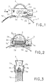
- Figures 1 to 3 show a screw collar constituted by a strip 1 generally metal, wound on itself and presenting, at least at its outer end 1a, troughs and reliefs forming a rack 1 b .
- a terminal 2 constituted by a simple U-shaped bracket, the bottom 2 a , located in the central zone of the terminal, is assembled to the strip by any suitable means, such as welding or riveting, or even by passing the strip through slots in said bottom.
- a curved blade 3 generally made of spring steel, for example profile semicircular, whose concavity is directed inwardly of the collar.
- the ends of the blade are in contact with the sides of the terminal and the blade is thus trapped therebetween.
- the blade 3 has two lateral extensions 3 b which penetrate into holes 2 c made on each side 2 b .
- the projections of the lateral extensions 3b are caulked on the outer face of the walls 2b or present a hook shape to ensure locking thereof on these sides.
- the blade 3 advantageously has two lateral extensions 3 d arranged in elongated slots 2 d of the lateral flanks 2 b of the terminal.
- the blade 3 is immobilized axially relative to the terminal 2 at its end 3 a , but is axially movable at its end 3 b , at least over the axial length of the slots 2 d forming a slide.
- the lower edge 2 e of the slots 2 d is advantageously inclined in the direction of the central zone of the terminal.
- a screw 4 is finally disposed between the lateral flanks 2 b of the terminal and its axis is substantially parallel to the bottom 2 a of the terminal, that is to say to the longitudinal direction of the strip in this region; it is held in its housing by the ends 3 a and 3 c , judiciously shaped, of the blade 3.
- the end 3 a has an at least partially circular opening 3 e , forming a bearing, in which the cylindrical end of the tail 4 a of the screw 4 is engaged .
- the end 3 c is similarly shaped and can also receive a cylindrical portion 4 b of the screw rod, located in the vicinity of its head 4 c .
- the cylindrical portion 4 a of the tail of the screw extends, below the end 3 a of the blade 3 , over a certain distance d when the head 4 c of the screw is in support, before tightening of the collar, on the movable end 3 c of the blade.
- the strip 1 being fixed to the terminal 2 as it has been described, its outer end 1 a is introduced, on the left of FIGS. 1 and 2, into the slot located between the bottom 2 a of the terminal and the threaded zone 4 d of the screw.
- a rotation of the screw 4 in the suitable direction advances the end 1a from left to right and reduces the diameter of the collar.
- the characteristics of the blade 3 which thus forms a spring, will be determined as a function of the clamping force which must be applied to the object to be clamped; similarly, the screwing torque exerted on the head of the screw 4 will take account of the desired tightening force, in particular if it is obtained by means of a motorized screwdriver. It is thus possible to limit the clamping force to any suitable value.
- the blade 3 would tend to return to its initial shape, thus ensuring that sufficient tightness is maintained.
- the terminal essentially has holes or the like intended to receive the lateral extensions of the ends of the blade to ensure the immobilization of one of these ends and allow the axial displacement of the other.
- the assembly of the bottom of the terminal and the band of the collar being made as well as that of the blade and the screw, these two sub-assemblies are secured to each other by a simple folding of the lateral flanks of the pod; this single operation constitutes the stirrup which traps the blade and the screw, the collar then being ready to be used.
Landscapes
- Engineering & Computer Science (AREA)
- General Engineering & Computer Science (AREA)
- Mechanical Engineering (AREA)
- Clamps And Clips (AREA)
- Gripping Jigs, Holding Jigs, And Positioning Jigs (AREA)
- Supports For Pipes And Cables (AREA)
- Dowels (AREA)
- Connections By Means Of Piercing Elements, Nuts, Or Screws (AREA)
- Aerials With Secondary Devices (AREA)
- Adhesives Or Adhesive Processes (AREA)
- Dental Preparations (AREA)
- Materials For Medical Uses (AREA)
Applications Claiming Priority (2)
| Application Number | Priority Date | Filing Date | Title |
|---|---|---|---|
| FR9206319 | 1992-05-22 | ||
| FR9206319 | 1992-05-22 |
Publications (2)
| Publication Number | Publication Date |
|---|---|
| EP0571294A1 true EP0571294A1 (de) | 1993-11-24 |
| EP0571294B1 EP0571294B1 (de) | 1997-01-08 |
Family
ID=9430106
Family Applications (1)
| Application Number | Title | Priority Date | Filing Date |
|---|---|---|---|
| EP93401311A Expired - Lifetime EP0571294B1 (de) | 1992-05-22 | 1993-05-21 | Gewindeklemmschelle |
Country Status (14)
| Country | Link |
|---|---|
| US (1) | US5327618A (de) |
| EP (1) | EP0571294B1 (de) |
| AT (1) | ATE147489T1 (de) |
| CA (1) | CA2096557C (de) |
| CZ (1) | CZ282228B6 (de) |
| DE (1) | DE69307184T2 (de) |
| DK (1) | DK0571294T3 (de) |
| ES (1) | ES2098691T3 (de) |
| GR (1) | GR3022587T3 (de) |
| HU (1) | HU216385B (de) |
| MX (1) | MX9303014A (de) |
| PL (1) | PL171496B1 (de) |
| RU (1) | RU2122661C1 (de) |
| SK (1) | SK279022B6 (de) |
Cited By (4)
| Publication number | Priority date | Publication date | Assignee | Title |
|---|---|---|---|---|
| FR2756356A1 (fr) * | 1996-11-25 | 1998-05-29 | Caillau Ets | Collier de serrage a boitier elastique |
| EP2017518A1 (de) * | 2007-07-16 | 2009-01-21 | Etablissements CAILLAU S.A.R.L. | Klemmvorrichtung mit Schlauchklemme und Positionierteil |
| CN108488159A (zh) * | 2017-04-14 | 2018-09-04 | Ms因泰克有限公司 | 开闭式架子固定夹 |
| CN110251367A (zh) * | 2019-06-24 | 2019-09-20 | 哈工大机器人(合肥)国际创新研究院 | 下肢康复机器人调节绑带、调节使用方法及松紧调节装置 |
Families Citing this family (10)
| Publication number | Priority date | Publication date | Assignee | Title |
|---|---|---|---|---|
| FR2728326B1 (fr) * | 1994-12-14 | 1997-05-23 | Calmettes Lionel | Collier de serrage d'une piece tubulaire |
| US5661876A (en) * | 1996-07-18 | 1997-09-02 | Goldenberg; Michael | Hose clamp |
| DE19653005B4 (de) * | 1996-12-19 | 2005-11-24 | Hans Oetiker Ag Maschinen- Und Apparatefabrik | Schlauchschelle |
| NL1006726C2 (nl) * | 1997-08-05 | 1999-02-08 | Walraven J Van Bv | Pijpbeugel. |
| US7055225B1 (en) * | 2003-07-09 | 2006-06-06 | Brant Jr John L | Hose clamp |
| KR100893038B1 (ko) | 2008-12-18 | 2009-04-15 | 윤성환 | 벨트식 클램프 |
| DE102011010655B3 (de) * | 2011-02-09 | 2012-07-26 | Norma Germany Gmbh | Spannschelle |
| KR101334852B1 (ko) * | 2011-07-25 | 2013-12-02 | 윤성환 | 벨트식 클램프 |
| KR101282795B1 (ko) | 2012-03-14 | 2013-07-05 | 이인재 | 원터치 잠금 버클식 스틸 밴드 클램프 |
| KR200473144Y1 (ko) | 2013-07-08 | 2014-06-17 | 프리론 주식회사 | 개선된 벨트타입 클램프 |
Citations (4)
| Publication number | Priority date | Publication date | Assignee | Title |
|---|---|---|---|---|
| US2504836A (en) * | 1945-06-08 | 1950-04-18 | Breese Corp Inc | Hose clamp |
| US2522494A (en) * | 1945-08-30 | 1950-09-19 | Baldo Louie | Hose clamp |
| WO1980001199A1 (en) * | 1978-12-07 | 1980-06-12 | B Andersson | Hose clamp |
| WO1987000602A1 (en) * | 1985-07-19 | 1987-01-29 | Research Corporation Limited | Hose clamp |
Family Cites Families (6)
| Publication number | Priority date | Publication date | Assignee | Title |
|---|---|---|---|---|
| US1986748A (en) * | 1933-02-23 | 1935-01-01 | Messrs Hunt & Turner Ltd | Clip for tubular hose and the like |
| US3195204A (en) * | 1964-04-23 | 1965-07-20 | Breeze Corp | Worm driven hose clamp |
| FR1484749A (fr) * | 1966-05-02 | 1967-06-16 | Caillau Ets | Collier de serrage |
| DE3130007A1 (de) * | 1981-07-30 | 1983-02-17 | Kurt 7238 Oberndorf Allert | Schlauchschelle |
| DE3941135C1 (en) * | 1989-12-13 | 1991-01-31 | Rasmussen Gmbh, 6457 Maintal, De | Hose clamp with fastening strap with overlapping ends - has clamping leaf spring, curved at less than 180 deg. in relieved state |
| US5063642A (en) * | 1990-04-19 | 1991-11-12 | Andras Toth | Quick release band clamp |
-
1993
- 1993-05-19 CA CA002096557A patent/CA2096557C/en not_active Expired - Fee Related
- 1993-05-19 US US08/064,757 patent/US5327618A/en not_active Expired - Lifetime
- 1993-05-20 PL PL93299014A patent/PL171496B1/pl unknown
- 1993-05-21 RU RU93005328/28A patent/RU2122661C1/ru not_active IP Right Cessation
- 1993-05-21 MX MX9303014A patent/MX9303014A/es not_active IP Right Cessation
- 1993-05-21 AT AT93401311T patent/ATE147489T1/de not_active IP Right Cessation
- 1993-05-21 HU HU9301503A patent/HU216385B/hu not_active IP Right Cessation
- 1993-05-21 SK SK521-93A patent/SK279022B6/sk unknown
- 1993-05-21 ES ES93401311T patent/ES2098691T3/es not_active Expired - Lifetime
- 1993-05-21 DE DE69307184T patent/DE69307184T2/de not_active Expired - Lifetime
- 1993-05-21 EP EP93401311A patent/EP0571294B1/de not_active Expired - Lifetime
- 1993-05-21 CZ CZ93975A patent/CZ282228B6/cs not_active IP Right Cessation
- 1993-05-21 DK DK93401311.1T patent/DK0571294T3/da active
-
1997
- 1997-02-19 GR GR970400272T patent/GR3022587T3/el unknown
Patent Citations (4)
| Publication number | Priority date | Publication date | Assignee | Title |
|---|---|---|---|---|
| US2504836A (en) * | 1945-06-08 | 1950-04-18 | Breese Corp Inc | Hose clamp |
| US2522494A (en) * | 1945-08-30 | 1950-09-19 | Baldo Louie | Hose clamp |
| WO1980001199A1 (en) * | 1978-12-07 | 1980-06-12 | B Andersson | Hose clamp |
| WO1987000602A1 (en) * | 1985-07-19 | 1987-01-29 | Research Corporation Limited | Hose clamp |
Cited By (9)
| Publication number | Priority date | Publication date | Assignee | Title |
|---|---|---|---|---|
| FR2756356A1 (fr) * | 1996-11-25 | 1998-05-29 | Caillau Ets | Collier de serrage a boitier elastique |
| WO1998023889A1 (fr) * | 1996-11-25 | 1998-06-04 | Etablissements Caillau | Collier de serrage a boitier elastique |
| EP2017518A1 (de) * | 2007-07-16 | 2009-01-21 | Etablissements CAILLAU S.A.R.L. | Klemmvorrichtung mit Schlauchklemme und Positionierteil |
| FR2919039A1 (fr) * | 2007-07-16 | 2009-01-23 | Caillau Ets | Dispositif de serrage avec collier de serrage et piece de positionnement |
| US7802821B2 (en) | 2007-07-16 | 2010-09-28 | Etablissements Caillau | Clamping device with a clamping collar and a positioning piece |
| RU2477209C2 (ru) * | 2007-07-16 | 2013-03-10 | Этаблиссман Кайо | Зажимное устройство с зажимным кольцом и установочной деталью |
| CN108488159A (zh) * | 2017-04-14 | 2018-09-04 | Ms因泰克有限公司 | 开闭式架子固定夹 |
| CN108488159B (zh) * | 2017-04-14 | 2021-10-08 | Ms因泰克有限公司 | 开闭式架子固定夹 |
| CN110251367A (zh) * | 2019-06-24 | 2019-09-20 | 哈工大机器人(合肥)国际创新研究院 | 下肢康复机器人调节绑带、调节使用方法及松紧调节装置 |
Also Published As
| Publication number | Publication date |
|---|---|
| PL299014A1 (en) | 1993-12-13 |
| CZ282228B6 (cs) | 1997-06-11 |
| CZ97593A3 (en) | 1994-05-18 |
| HUT68868A (en) | 1995-08-28 |
| EP0571294B1 (de) | 1997-01-08 |
| DE69307184D1 (de) | 1997-02-20 |
| GR3022587T3 (en) | 1997-05-31 |
| CA2096557C (en) | 1999-12-14 |
| RU2122661C1 (ru) | 1998-11-27 |
| DK0571294T3 (da) | 1997-07-07 |
| HU216385B (hu) | 1999-06-28 |
| ATE147489T1 (de) | 1997-01-15 |
| CA2096557A1 (en) | 1993-11-23 |
| ES2098691T3 (es) | 1997-05-01 |
| MX9303014A (es) | 1995-01-31 |
| SK279022B6 (sk) | 1998-05-06 |
| PL171496B1 (en) | 1997-05-30 |
| DE69307184T2 (de) | 1997-07-10 |
| HU9301503D0 (en) | 1993-09-28 |
| SK52193A3 (en) | 1993-12-08 |
| US5327618A (en) | 1994-07-12 |
Similar Documents
| Publication | Publication Date | Title |
|---|---|---|
| EP0113624B1 (de) | Schlauchschelle | |
| EP0571294B1 (de) | Gewindeklemmschelle | |
| EP0434825B1 (de) | Schnell montierbare mutter | |
| EP0336808A1 (de) | Einsteckbare Klammer mit innenliegendem Mechanismus | |
| EP0003192A1 (de) | Wiederbrauchbare Spannschelle | |
| FR2629030A1 (fr) | Porte-balais d'essuie-glace comportant un verrou | |
| FR2493428A1 (fr) | Collier de serrage forme d'une boucle de feuillard d'acier | |
| EP0493182A1 (de) | Rohrschelle | |
| CH625864A5 (de) | ||
| EP0724106A1 (de) | Rohrschelle | |
| CH382697A (fr) | Appareil de coupe destiné à couper transversalement une pièce allongée | |
| EP0286561B1 (de) | Schelle mit gelenkig gelagerter Spannschraube | |
| EP1540229A1 (de) | Klemmring | |
| EP0797718B1 (de) | Provisorischer türanschlag für ein kraftfahrzeugscharnier und vorrichtung um diesen anzubringen | |
| FR2505449A1 (fr) | Collier de serrage | |
| EP0798186B1 (de) | Wischerarm für eine Scheibenwischeranlage,insbesondere für Kraftfahrzeuge | |
| FR2817931A1 (fr) | Montage d'ecrou | |
| EP0326481A1 (de) | Zangenförmige Mutter und damit erfolgter Zusammenbau | |
| FR2593730A1 (fr) | Outil de rivetage pour le rivetage unilateral d'ecrous a river | |
| FR2752793A1 (fr) | Dispositif pour fixer une barre porte-charge sur le toit d'un vehicule automobile | |
| BE898532A (fr) | Ensemble d'un élément de friction équipé d'un ressort anti-bruit pour frein à disque. | |
| FR2695693A1 (fr) | Dispositif d'immobilisation d'une gaine de câble sur un support quelconque. | |
| EP0323338B1 (de) | Vorrichtung zur Verbindung von zwei zurückversetzten Flanschen bei der Montage von Abgasrohren | |
| FR2683869A1 (fr) | Collier de serrage. | |
| CH638874A5 (fr) | Appareil pour la pose d'un dispositif d'attache. |
Legal Events
| Date | Code | Title | Description |
|---|---|---|---|
| PUAI | Public reference made under article 153(3) epc to a published international application that has entered the european phase |
Free format text: ORIGINAL CODE: 0009012 |
|
| AK | Designated contracting states |
Kind code of ref document: A1 Designated state(s): AT BE CH DE DK ES FR GB GR IE IT LI LU MC NL PT SE |
|
| 17P | Request for examination filed |
Effective date: 19940413 |
|
| 17Q | First examination report despatched |
Effective date: 19950912 |
|
| GRAG | Despatch of communication of intention to grant |
Free format text: ORIGINAL CODE: EPIDOS AGRA |
|
| GRAH | Despatch of communication of intention to grant a patent |
Free format text: ORIGINAL CODE: EPIDOS IGRA |
|
| GRAH | Despatch of communication of intention to grant a patent |
Free format text: ORIGINAL CODE: EPIDOS IGRA |
|
| GRAA | (expected) grant |
Free format text: ORIGINAL CODE: 0009210 |
|
| AK | Designated contracting states |
Kind code of ref document: B1 Designated state(s): AT BE CH DE DK ES FR GB GR IE IT LI LU MC NL PT SE |
|
| REF | Corresponds to: |
Ref document number: 147489 Country of ref document: AT Date of ref document: 19970115 Kind code of ref document: T |
|
| REG | Reference to a national code |
Ref country code: CH Ref legal event code: EP |
|
| REG | Reference to a national code |
Ref country code: CH Ref legal event code: NV Representative=s name: BOVARD AG PATENTANWAELTE |
|
| GBT | Gb: translation of ep patent filed (gb section 77(6)(a)/1977) |
Effective date: 19970125 |
|
| REF | Corresponds to: |
Ref document number: 69307184 Country of ref document: DE Date of ref document: 19970220 |
|
| REG | Reference to a national code |
Ref country code: IE Ref legal event code: FG4D Free format text: 71423 |
|
| ITF | It: translation for a ep patent filed | ||
| REG | Reference to a national code |
Ref country code: GR Ref legal event code: FG4A Free format text: 3022587 |
|
| REG | Reference to a national code |
Ref country code: ES Ref legal event code: FG2A Ref document number: 2098691 Country of ref document: ES Kind code of ref document: T3 |
|
| REG | Reference to a national code |
Ref country code: PT Ref legal event code: SC4A Free format text: AVAILABILITY OF NATIONAL TRANSLATION Effective date: 19970321 |
|
| REG | Reference to a national code |
Ref country code: DK Ref legal event code: T3 |
|
| PLBE | No opposition filed within time limit |
Free format text: ORIGINAL CODE: 0009261 |
|
| STAA | Information on the status of an ep patent application or granted ep patent |
Free format text: STATUS: NO OPPOSITION FILED WITHIN TIME LIMIT |
|
| 26N | No opposition filed | ||
| REG | Reference to a national code |
Ref country code: GB Ref legal event code: IF02 |
|
| PGFP | Annual fee paid to national office [announced via postgrant information from national office to epo] |
Ref country code: AT Payment date: 20030415 Year of fee payment: 11 |
|
| PGFP | Annual fee paid to national office [announced via postgrant information from national office to epo] |
Ref country code: NL Payment date: 20030416 Year of fee payment: 11 Ref country code: MC Payment date: 20030416 Year of fee payment: 11 Ref country code: LU Payment date: 20030416 Year of fee payment: 11 |
|
| PGFP | Annual fee paid to national office [announced via postgrant information from national office to epo] |
Ref country code: GR Payment date: 20030422 Year of fee payment: 11 Ref country code: DK Payment date: 20030422 Year of fee payment: 11 |
|
| PGFP | Annual fee paid to national office [announced via postgrant information from national office to epo] |
Ref country code: IE Payment date: 20030423 Year of fee payment: 11 |
|
| PGFP | Annual fee paid to national office [announced via postgrant information from national office to epo] |
Ref country code: CH Payment date: 20030515 Year of fee payment: 11 |
|
| PGFP | Annual fee paid to national office [announced via postgrant information from national office to epo] |
Ref country code: PT Payment date: 20030527 Year of fee payment: 11 |
|
| PGFP | Annual fee paid to national office [announced via postgrant information from national office to epo] |
Ref country code: BE Payment date: 20030603 Year of fee payment: 11 |
|
| PG25 | Lapsed in a contracting state [announced via postgrant information from national office to epo] |
Ref country code: LU Free format text: LAPSE BECAUSE OF NON-PAYMENT OF DUE FEES Effective date: 20040521 Ref country code: IE Free format text: LAPSE BECAUSE OF NON-PAYMENT OF DUE FEES Effective date: 20040521 Ref country code: AT Free format text: LAPSE BECAUSE OF NON-PAYMENT OF DUE FEES Effective date: 20040521 |
|
| PG25 | Lapsed in a contracting state [announced via postgrant information from national office to epo] |
Ref country code: MC Free format text: LAPSE BECAUSE OF NON-PAYMENT OF DUE FEES Effective date: 20040531 Ref country code: LI Free format text: LAPSE BECAUSE OF NON-PAYMENT OF DUE FEES Effective date: 20040531 Ref country code: CH Free format text: LAPSE BECAUSE OF NON-PAYMENT OF DUE FEES Effective date: 20040531 Ref country code: BE Free format text: LAPSE BECAUSE OF NON-PAYMENT OF DUE FEES Effective date: 20040531 |
|
| PG25 | Lapsed in a contracting state [announced via postgrant information from national office to epo] |
Ref country code: DK Free format text: LAPSE BECAUSE OF NON-PAYMENT OF DUE FEES Effective date: 20040601 |
|
| PG25 | Lapsed in a contracting state [announced via postgrant information from national office to epo] |
Ref country code: PT Free format text: LAPSE BECAUSE OF NON-PAYMENT OF DUE FEES Effective date: 20041122 |
|
| BERE | Be: lapsed |
Owner name: ETS *CAILLAU Effective date: 20040531 |
|
| PG25 | Lapsed in a contracting state [announced via postgrant information from national office to epo] |
Ref country code: NL Free format text: LAPSE BECAUSE OF NON-PAYMENT OF DUE FEES Effective date: 20041201 |
|
| PG25 | Lapsed in a contracting state [announced via postgrant information from national office to epo] |
Ref country code: GR Free format text: LAPSE BECAUSE OF NON-PAYMENT OF DUE FEES Effective date: 20041203 |
|
| REG | Reference to a national code |
Ref country code: DK Ref legal event code: EBP |
|
| REG | Reference to a national code |
Ref country code: CH Ref legal event code: PL |
|
| REG | Reference to a national code |
Ref country code: PT Ref legal event code: MM4A Effective date: 20041122 |
|
| NLV4 | Nl: lapsed or anulled due to non-payment of the annual fee |
Effective date: 20041201 |
|
| REG | Reference to a national code |
Ref country code: IE Ref legal event code: MM4A |
|
| PGFP | Annual fee paid to national office [announced via postgrant information from national office to epo] |
Ref country code: GB Payment date: 20060505 Year of fee payment: 14 |
|
| GBPC | Gb: european patent ceased through non-payment of renewal fee |
Effective date: 20070521 |
|
| PG25 | Lapsed in a contracting state [announced via postgrant information from national office to epo] |
Ref country code: GB Free format text: LAPSE BECAUSE OF NON-PAYMENT OF DUE FEES Effective date: 20070521 |
|
| PGFP | Annual fee paid to national office [announced via postgrant information from national office to epo] |
Ref country code: ES Payment date: 20080522 Year of fee payment: 16 |
|
| PGFP | Annual fee paid to national office [announced via postgrant information from national office to epo] |
Ref country code: SE Payment date: 20080418 Year of fee payment: 16 |
|
| REG | Reference to a national code |
Ref country code: ES Ref legal event code: FD2A Effective date: 20090522 |
|
| PGFP | Annual fee paid to national office [announced via postgrant information from national office to epo] |
Ref country code: DE Payment date: 20100512 Year of fee payment: 18 |
|
| PG25 | Lapsed in a contracting state [announced via postgrant information from national office to epo] |
Ref country code: ES Free format text: LAPSE BECAUSE OF NON-PAYMENT OF DUE FEES Effective date: 20090522 |
|
| PG25 | Lapsed in a contracting state [announced via postgrant information from national office to epo] |
Ref country code: SE Free format text: LAPSE BECAUSE OF NON-PAYMENT OF DUE FEES Effective date: 20090522 |
|
| REG | Reference to a national code |
Ref country code: DE Ref legal event code: R119 Ref document number: 69307184 Country of ref document: DE |
|
| REG | Reference to a national code |
Ref country code: DE Ref legal event code: R119 Ref document number: 69307184 Country of ref document: DE |
|
| PGFP | Annual fee paid to national office [announced via postgrant information from national office to epo] |
Ref country code: FR Payment date: 20120625 Year of fee payment: 20 |
|
| PGFP | Annual fee paid to national office [announced via postgrant information from national office to epo] |
Ref country code: IT Payment date: 20120522 Year of fee payment: 20 |
|
| PG25 | Lapsed in a contracting state [announced via postgrant information from national office to epo] |
Ref country code: DE Free format text: LAPSE BECAUSE OF NON-PAYMENT OF DUE FEES Effective date: 20111130 |