EP0567099B1 - Bewegungspuffer für eine Personenbeförderungsvorrichtung - Google Patents
Bewegungspuffer für eine Personenbeförderungsvorrichtung Download PDFInfo
- Publication number
- EP0567099B1 EP0567099B1 EP93106495A EP93106495A EP0567099B1 EP 0567099 B1 EP0567099 B1 EP 0567099B1 EP 93106495 A EP93106495 A EP 93106495A EP 93106495 A EP93106495 A EP 93106495A EP 0567099 B1 EP0567099 B1 EP 0567099B1
- Authority
- EP
- European Patent Office
- Prior art keywords
- car
- wedge
- guide rail
- buffer
- leaf springs
- Prior art date
- Legal status (The legal status is an assumption and is not a legal conclusion. Google has not performed a legal analysis and makes no representation as to the accuracy of the status listed.)
- Expired - Lifetime
Links
Images
Classifications
-
- B—PERFORMING OPERATIONS; TRANSPORTING
- B66—HOISTING; LIFTING; HAULING
- B66B—ELEVATORS; ESCALATORS OR MOVING WALKWAYS
- B66B5/00—Applications of checking, fault-correcting, or safety devices in elevators
- B66B5/28—Buffer-stops for cars, cages, or skips
-
- B—PERFORMING OPERATIONS; TRANSPORTING
- B66—HOISTING; LIFTING; HAULING
- B66B—ELEVATORS; ESCALATORS OR MOVING WALKWAYS
- B66B7/00—Other common features of elevators
- B66B7/02—Guideways; Guides
- B66B7/023—Mounting means therefor
- B66B7/027—Mounting means therefor for mounting auxiliary devices
-
- B—PERFORMING OPERATIONS; TRANSPORTING
- B66—HOISTING; LIFTING; HAULING
- B66B—ELEVATORS; ESCALATORS OR MOVING WALKWAYS
- B66B5/00—Applications of checking, fault-correcting, or safety devices in elevators
- B66B5/02—Applications of checking, fault-correcting, or safety devices in elevators responsive to abnormal operating conditions
- B66B5/16—Braking or catch devices operating between cars, cages, or skips and fixed guide elements or surfaces in hoistway or well
- B66B5/18—Braking or catch devices operating between cars, cages, or skips and fixed guide elements or surfaces in hoistway or well and applying frictional retarding forces
- B66B5/22—Braking or catch devices operating between cars, cages, or skips and fixed guide elements or surfaces in hoistway or well and applying frictional retarding forces by means of linearly-movable wedges
-
- B—PERFORMING OPERATIONS; TRANSPORTING
- B66—HOISTING; LIFTING; HAULING
- B66B—ELEVATORS; ESCALATORS OR MOVING WALKWAYS
- B66B5/00—Applications of checking, fault-correcting, or safety devices in elevators
- B66B5/28—Buffer-stops for cars, cages, or skips
- B66B5/282—Structure thereof
-
- B—PERFORMING OPERATIONS; TRANSPORTING
- B66—HOISTING; LIFTING; HAULING
- B66B—ELEVATORS; ESCALATORS OR MOVING WALKWAYS
- B66B7/00—Other common features of elevators
- B66B7/02—Guideways; Guides
- B66B7/04—Riding means, e.g. Shoes, Rollers, between car and guiding means, e.g. rails, ropes
- B66B7/047—Shoes, sliders
Definitions
- This invention relates to a buffer and a method for stopping a car traveling along a guide rail.
- a buffer having the features of the pre-characterizing part of claim 1 is known from DE-A-928 367.
- a first speed limiting device is typically an electromechanical device which reduces or eliminates the power to the drive. If the first speed limiting device fails, as it would if the ropes suspending the car were to fail, then a second speed limiting device is implemented.
- the second speed limiting device is typically a centrifugally actuated mechanical device.
- a centrifugally operated brake grips a governor rope in an overspeed condition.
- the governor rope actuates a pair of safeties attached to the car.
- the safeties frictionally grip the guide rails of the elevator, thereby causing the elevator car to stop.
- a motion buffer is positioned in the bottom, or "pit", of the hoistway.
- the first category may be described as coil spring buffers. These buffers are basically large, stiff coil springs which dampen and dissipate the motion of the elevator. The problem with this type of buffer is that the elevator may rebound a number of times before the spring totally dissipates the energy of the car. The bouncing motion of the elevator represents a safety hazard.
- the second category of buffers may be described as hydraulic buffers.
- Hydraulic buffers generally comprise a hydraulic cylinder having a fluid. Under force, fluid in the cap end of the cylinder passes through orifices to the rod end of the cylinder. The energy of the car striking the cylinder rod is dissipated as the fluid passes between the two compartments.
- the disadvantages of this type buffer is that the cylinder requires a relatively long stroke to stop the car, especially in high-rise applications.
- the third category of buffers may be described as frangible buffers.
- Frangible buffers typically comprise a cylinder and a truncated cone. When the car travels far enough, the cylinder is forced on the cone, causing the cylinder to deform into a plurality of sections. The deformation of the cylinder dissipates the energy of the car.
- the disadvantage of this type of buffer is that once a buffer has been used, the cylinder must be replaced.
- DE-A-928 367 discloses a buffer in which the ends of each guide rail are split into halves forming an acute angle with respect to the longitudinal axis of the guide rail, a wedge being provided between said halves so as to vary said angle.
- the means mounted on the car and encountering said halves of the guide rail ends are shoe members used for positioning the car in relation to the guide rails. Once the buffer has been used, said wedge must be displaced so as to decrease said angle between the split end portions of the guide rails and releave the car from its clamped condition.
- Such buffer is provided by the present invention according to claim 1.
- an object of the present invention to provide a buffer which may be used more than one time.
- a motion buffer for stopping a car traveling along a guide rail having a wedge and a biasing means for biasing against the wedge. If the car travels far enough along the guide rail to encounter the wedge, the biasing means becomes biased against the wedge, thereby stopping the car.
- the biasing means comprises a pair, of leaf springs, mounted on the car.
- the biasing means encounters the wedge, the leaf springs are laterally deflected, thereby stopping the car.
- a method for stopping an elevator car traveling along the guide rail is provided.
- One advantage of the present invention is that the present invention may be used more than one time. As a result, the buffer may be used for testing or actual situations without having to be replaced.
- a further advantage of the present invention is that the present invention absorbs all the energy of the car, thereby preventing the car from rebounding and possibly causing injury to passengers within the car.
- a still further advantage of the present invention is that the present invention mounts on the car and the guide rails, thereby minimizing the necessary hoistway space.
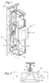
- Fig. 1 is a diagrammatic view of an elevator.
- Fig. 2 is a bottom view of the biasing means attached to the elevator car of FIG. 1 (guide rail not shown).
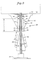
- Fig. 3 is a diagrammatic view of the biasing means and wedge of FIG. 1.
- an elevator 10 having a car 12 and a counterweight 14 attached to each other by a plurality of ropes 16.
- the ropes 16 extend upwardly from the car 12 to a plurality of sheaves 18 located at the top 20 of the hoistway 22. After passing over the sheaves 18, the ropes 16 extend back downwardly to a counterweight 14.
- the car 12 and the counterweight 14 are constrained to vertical motion within the hoistway 22 by a pair of first 24 and second 26 guide rails, respectively.
- a buffer 28, having a wedge 30 and a biasing means 32 is provided on each side of the car 12 (see FIG. 1) to stop the car 12 at the bottom 34 of the hoistway 22 if necessary.
- Each wedge 30 has a first surface 36 and a second surface 38 oriented at an acute angle 40 from the centerline of the wedge 30.
- Each biasing means 32 comprises a pair of guide shoes 42 and a pair of leaf springs 44, having a first 46 and second end 48.
- a bracket 50 for mounting the biasing means 32 has a first face 52 (see FIG.2) and a second face 54.
- the second face 54 includes a plurality of slots 56 and holes 58.
- the guide shoes 42 are fixed to the leaf springs 44 by conventional means such as a threaded fastener (not shown).
- a conventional attachment means such as a hardened bolt 60, fixes the first end 46 of each leaf spring 44 to the first face 52 of each bracket 50, thereby making each leaf spring 44 a cantilever.
- E v kinetic energy
- E h potential energy
- each buffer 28 can be determined for a particular application.
- a wedge 30 is fixed to each first guide rail 24 at the bottom 34 of the hoistway 22.
- the wedge 30 is positioned so that the point of the wedge 30 points upwardly.
- the biasing means 32 is mounted on the bottom of each side of the car 12 adjacent the first guide rails 24.
- the wedge 30 and biasing means 32 may be positioned at a position other than the bottom of the hoistway and car, respectively.
- the wedge 30 and biasing means 32 could be positioned along side the car 12 when the car 12 is at, or near, the bottom 34 of the hoistway 22.
- the biasing means 32 on each side of the car 12 is attached to the first face 52 of the bracket 50.
- the second face 54 of each bracket 50 is fixed to the car 12.
- the plurality of slots 56 in the second face 54 enable the bracket 50, and therefore the biasing means 32, to be adjustably positioned in close proximity to the first guide rails 24.
- each buffer 28 the leaf springs 44 of each buffer 28 are positioned on opposite sides of each first guide rail 24, such that the attached guide shoes 42 face the guide rail 24.
- the first end 46 of each leaf spring 44 is fixed to the bracket 50 by a pair of hardened bolts 60.
- the cantilever leaf springs 44 may be attached by a variety of fasteners and ⁇ or mounting brackets.
- the biasing means 32 may be used without guide shoes 42.
- the present invention provides a number of advantages over the existing buffer art: First, the buffer 28 may be used more than once; Second, the wedge 30 and biasing means 32 arrangement prevents the car 12 from rebounding; and Third, the wedge 30 and biasing means 32 arrangement may be positioned at the bottom 34 of the hoistway 22 or along side the car 22 when the car 12 is at the bottom 34 of the hoistway 22. In any case, the space requirements of the buffer 28 and the hoistway 22 are minimized.
Landscapes
- Engineering & Computer Science (AREA)
- Mechanical Engineering (AREA)
- Lift-Guide Devices, And Elevator Ropes And Cables (AREA)
- Maintenance And Inspection Apparatuses For Elevators (AREA)
- Platform Screen Doors And Railroad Systems (AREA)
Claims (2)
- Stoßabsorber (28) zum Anhalten einer Kabine (12), die entlang einer Führungsschiene (24) fährt, aufweisend:ein Keilelement (30), das an der Führungsschiene (24) angebracht ist; undeine Einrichtung (32) mit Führungsschuhen (42), die an der Kabine (12) in enger Nähe zu der Führungsschiene (24) angebracht ist;wobei, wenn die Kabine (12) entlang der Führungsschiene (24) weit genug fährt, um auf das Keilelement (30) zu treffen, die Einrichtung (32) mit den Führungsschuhen (42) auf das Keilelement trifft und zum Anhalten der Kabine gegen das Keilelement (30) gespannt wird,dadurch gekennzeichnet,
daß die Einrichtung (32), die auf das Keilelement (30) trifft, eine Spanneinrichtung (32) ist und aufweist:ein Paar von Blattfedern (44) mit einer Länge (l), die von einem ersten Ende (46) und einem zweiten Ende (48) definiert ist;eine Befestigungseinrichtung (60), die das erste Ende (46) einer jeden Blattfeder (44) an der Kabine (12) in enger Nähe zu der Führungsschiene (24) befestigt, undein Paar der Führungsschuhe (42), die an dem zweiten Ende (48) der Blattfedern (44) auf die Führungsschiene (24) gerichtet angebracht sind;wobei, wenn die Kabine (12) entlang der Führungsschiene (24) weit genug fährt, um auf das Keilelement (30) zu treffen, die Blattfedern (44) die Führungsschuhe (42) gegen das Keilelement (30) spannen und so die Kabine (12) anhalten. - Stoßabsorber nach Anspruch 1, ferner aufweisend:einen Halter (30) zum Anbringen der Blattfedern (44) an der Kabine (12), der eine Einrichtung (56) zum einstellbar Positionieren der Blattfedern (44) relativ zu der Führungsschiene (24) besitzt.
Applications Claiming Priority (2)
| Application Number | Priority Date | Filing Date | Title |
|---|---|---|---|
| JP25742/92 | 1992-04-22 | ||
| JP1992025742U JP2528437Y2 (ja) | 1992-04-22 | 1992-04-22 | エレベーターの緩衝器 |
Publications (3)
| Publication Number | Publication Date |
|---|---|
| EP0567099A2 EP0567099A2 (de) | 1993-10-27 |
| EP0567099A3 EP0567099A3 (de) | 1993-11-18 |
| EP0567099B1 true EP0567099B1 (de) | 1997-07-09 |
Family
ID=12174280
Family Applications (1)
| Application Number | Title | Priority Date | Filing Date |
|---|---|---|---|
| EP93106495A Expired - Lifetime EP0567099B1 (de) | 1992-04-22 | 1993-04-21 | Bewegungspuffer für eine Personenbeförderungsvorrichtung |
Country Status (6)
| Country | Link |
|---|---|
| US (1) | US5370207A (de) |
| EP (1) | EP0567099B1 (de) |
| JP (1) | JP2528437Y2 (de) |
| KR (1) | KR930021529A (de) |
| DE (1) | DE69311954T2 (de) |
| ES (1) | ES2104993T3 (de) |
Families Citing this family (10)
| Publication number | Priority date | Publication date | Assignee | Title |
|---|---|---|---|---|
| JP4301837B2 (ja) * | 2002-05-21 | 2009-07-22 | 三菱電機株式会社 | エレベータの緩衝装置 |
| US20060225967A1 (en) * | 2002-07-16 | 2006-10-12 | Shusaku Shibasaki | Conical spring buffer for an elevator |
| ZA200503290B (en) * | 2004-05-19 | 2007-03-28 | Inventioag | Shaft pit equipment for a lift |
| EP1598301B1 (de) * | 2004-05-19 | 2012-07-18 | Inventio AG | Schachtgrubenausrüstung für einen Aufzug |
| EP1928776B1 (de) * | 2005-09-29 | 2012-08-22 | Otis Elevator Company | Zerbrechbarer puffer für ein aufzugssystem mit mehreren kabinen in einem schacht |
| JP4917798B2 (ja) * | 2005-12-09 | 2012-04-18 | 日本オーチス・エレベータ株式会社 | エレベータの緩衝器 |
| CN101397100B (zh) * | 2007-09-29 | 2010-09-08 | 宝山钢铁股份有限公司 | 一种卸卷小车的托辊刹车装置 |
| CN102092619A (zh) * | 2011-01-17 | 2011-06-15 | 王后忠 | 一种导轨式升降平台 |
| CN103538994B (zh) * | 2013-09-29 | 2015-03-04 | 中国矿业大学 | 一种大型双层罐笼可调式中间盘体及其调移方法 |
| EP3257800B1 (de) * | 2016-06-15 | 2019-02-27 | KONE Corporation | Aufzug |
Family Cites Families (13)
| Publication number | Priority date | Publication date | Assignee | Title |
|---|---|---|---|---|
| US568345A (en) * | 1896-09-29 | Safety-cushion for elevators | ||
| US947477A (en) * | 1909-11-11 | 1910-01-25 | Ernest C Wilcox | Shock-absorber. |
| FR795965A (fr) * | 1935-10-04 | 1936-03-26 | Perfectionnements aux ressorts à lames | |
| FR812816A (fr) * | 1935-11-04 | 1937-05-19 | Limiteur de course pour cages de mine | |
| DE928367C (de) * | 1951-02-23 | 1955-05-31 | Wilhelm Gerk | Einrichtung zum Verhindern des UEbertreibens der Foerderkoerbe von Bergwerksfoerderanlagen |
| DE942412C (de) * | 1952-01-29 | 1956-05-03 | Wilhelm Jaeger | Einrichtung zum Verhindern des UEbertreibens der Foerderkoerbe von Bergwerksfoerderanlagen u. dgl. |
| US3327811A (en) * | 1966-10-28 | 1967-06-27 | Otis Elevator Co | Governor |
| GB1226439A (de) * | 1968-12-09 | 1971-03-31 | ||
| AT343856B (de) * | 1976-04-05 | 1978-06-26 | Inventio Ag | Federpuffer fur aufzugsanlagen |
| DE2814114A1 (de) * | 1978-04-01 | 1979-10-04 | Guenter Grigoleit | Einrichtung zum abbremsen der aufzugsfahrkoerbe o.dgl. zur vermeidung des harten aufsetzens auf die unteren fahrbegrenzungen |
| EP0021698B1 (de) * | 1979-06-08 | 1983-11-02 | Oleo International Holdings Limited | Stossdämpfervorrichtungen |
| PL139894B1 (en) * | 1983-08-17 | 1987-03-31 | Akad Gorniczo Hutnicza | Apparatus for emergency braking gin tubs in shafts on free pass paths sections |
| SU1331785A1 (ru) * | 1986-01-07 | 1987-08-23 | Центральное Проектно-Конструкторское Бюро По Лифтам Всесоюзного Промышленного Объединения "Союзлифтмаш" | Ловитель лифта |
-
1992
- 1992-04-22 JP JP1992025742U patent/JP2528437Y2/ja not_active Expired - Lifetime
-
1993
- 1993-04-14 US US08/047,218 patent/US5370207A/en not_active Expired - Fee Related
- 1993-04-21 EP EP93106495A patent/EP0567099B1/de not_active Expired - Lifetime
- 1993-04-21 KR KR1019930006724A patent/KR930021529A/ko not_active Application Discontinuation
- 1993-04-21 DE DE69311954T patent/DE69311954T2/de not_active Expired - Fee Related
- 1993-04-21 ES ES93106495T patent/ES2104993T3/es not_active Expired - Lifetime
Also Published As
| Publication number | Publication date |
|---|---|
| EP0567099A3 (de) | 1993-11-18 |
| US5370207A (en) | 1994-12-06 |
| ES2104993T3 (es) | 1997-10-16 |
| JP2528437Y2 (ja) | 1997-03-12 |
| KR930021529A (ko) | 1993-11-22 |
| DE69311954D1 (de) | 1997-08-14 |
| EP0567099A2 (de) | 1993-10-27 |
| DE69311954T2 (de) | 1998-02-19 |
| JPH0585778U (ja) | 1993-11-19 |
Similar Documents
| Publication | Publication Date | Title |
|---|---|---|
| US5526901A (en) | Two car elevator system | |
| JP5315458B2 (ja) | 圧延管表面ドラッグによる運動摩擦力と圧延力を用いた車両衝撃を吸収する方法、及びこれを用いた車両衝撃吸収装置 | |
| US5301773A (en) | Positive terminal overspeed protection by rail grabbing | |
| EP0567099B1 (de) | Bewegungspuffer für eine Personenbeförderungsvorrichtung | |
| US5495919A (en) | Safety brake apparatus for an elevator car or counterweight | |
| ES2331052T3 (es) | Dispositivo y procedimiento para desbloquear un sistema paracaidas. | |
| FI98295C (fi) | Tarraaja | |
| ES2043130T3 (es) | Dispositivo que impide las aceleraciones o movimintos incontrolados deuna cabina o portacargas. . | |
| US5195616A (en) | One to two stroke roped elevator pit buffers | |
| EP0372574A1 (de) | Stützstruktur einer Führungsschiene für Aufzugsysteme | |
| DE59406874D1 (de) | Fang- und Blockiereinrichtung für einen auf Laufschienen geführten Laufwagen eines Schräg- oder Senkrechtaufzugs | |
| EP1928776B1 (de) | Zerbrechbarer puffer für ein aufzugssystem mit mehreren kabinen in einem schacht | |
| CN111392542B (zh) | 一种双向安全钳 | |
| US20020134618A1 (en) | Device for progressively braking the fall of a load, and life saving line equipped with said device | |
| JPH06211465A (ja) | エレベーター用張り車装置 | |
| US5238088A (en) | Pit buffer assembly for high speed elevators | |
| JP2635249B2 (ja) | ロープレスリニアモータエレベーターの安全装置 | |
| WO2003072479A1 (en) | Elevator governor rope tensioning | |
| US6981575B2 (en) | Concrete rail safety device for an elevator car | |
| CN212500241U (zh) | 碰撞消能装置以及汽车 | |
| KR950031859A (ko) | 엘리베이터의 안전정지장치 | |
| JPH05155554A (ja) | エレベータの緩衝装置 | |
| JPH072466A (ja) | 主索なしエレベーター装置 | |
| WO1992013791A1 (en) | Decelerating device | |
| SU808355A1 (ru) | Лифт |
Legal Events
| Date | Code | Title | Description |
|---|---|---|---|
| PUAI | Public reference made under article 153(3) epc to a published international application that has entered the european phase |
Free format text: ORIGINAL CODE: 0009012 |
|
| PUAL | Search report despatched |
Free format text: ORIGINAL CODE: 0009013 |
|
| AK | Designated contracting states |
Kind code of ref document: A2 Designated state(s): CH DE ES IT LI |
|
| AK | Designated contracting states |
Kind code of ref document: A3 Designated state(s): CH DE ES IT LI |
|
| 17P | Request for examination filed |
Effective date: 19940322 |
|
| 17Q | First examination report despatched |
Effective date: 19950609 |
|
| GRAG | Despatch of communication of intention to grant |
Free format text: ORIGINAL CODE: EPIDOS AGRA |
|
| GRAH | Despatch of communication of intention to grant a patent |
Free format text: ORIGINAL CODE: EPIDOS IGRA |
|
| ITF | It: translation for a ep patent filed |
Owner name: BARZANO' E ZANARDO ROMA S.P.A. |
|
| GRAH | Despatch of communication of intention to grant a patent |
Free format text: ORIGINAL CODE: EPIDOS IGRA |
|
| GRAA | (expected) grant |
Free format text: ORIGINAL CODE: 0009210 |
|
| AK | Designated contracting states |
Kind code of ref document: B1 Designated state(s): CH DE ES IT LI |
|
| REG | Reference to a national code |
Ref country code: CH Ref legal event code: EP |
|
| REF | Corresponds to: |
Ref document number: 69311954 Country of ref document: DE Date of ref document: 19970814 |
|
| REG | Reference to a national code |
Ref country code: ES Ref legal event code: FG2A Ref document number: 2104993 Country of ref document: ES Kind code of ref document: T3 |
|
| REG | Reference to a national code |
Ref country code: CH Ref legal event code: NV Representative=s name: E. BLUM & CO. PATENTANWAELTE |
|
| PGFP | Annual fee paid to national office [announced via postgrant information from national office to epo] |
Ref country code: DE Payment date: 19980325 Year of fee payment: 6 |
|
| PGFP | Annual fee paid to national office [announced via postgrant information from national office to epo] |
Ref country code: CH Payment date: 19980403 Year of fee payment: 6 |
|
| PGFP | Annual fee paid to national office [announced via postgrant information from national office to epo] |
Ref country code: ES Payment date: 19980415 Year of fee payment: 6 |
|
| PLBE | No opposition filed within time limit |
Free format text: ORIGINAL CODE: 0009261 |
|
| STAA | Information on the status of an ep patent application or granted ep patent |
Free format text: STATUS: NO OPPOSITION FILED WITHIN TIME LIMIT |
|
| 26N | No opposition filed | ||
| PG25 | Lapsed in a contracting state [announced via postgrant information from national office to epo] |
Ref country code: ES Free format text: LAPSE BECAUSE OF NON-PAYMENT OF DUE FEES Effective date: 19990422 |
|
| PG25 | Lapsed in a contracting state [announced via postgrant information from national office to epo] |
Ref country code: LI Free format text: LAPSE BECAUSE OF NON-PAYMENT OF DUE FEES Effective date: 19990430 Ref country code: CH Free format text: LAPSE BECAUSE OF NON-PAYMENT OF DUE FEES Effective date: 19990430 |
|
| REG | Reference to a national code |
Ref country code: CH Ref legal event code: PL |
|
| PG25 | Lapsed in a contracting state [announced via postgrant information from national office to epo] |
Ref country code: DE Free format text: LAPSE BECAUSE OF NON-PAYMENT OF DUE FEES Effective date: 20000201 |
|
| REG | Reference to a national code |
Ref country code: ES Ref legal event code: FD2A Effective date: 20010503 |
|
| PG25 | Lapsed in a contracting state [announced via postgrant information from national office to epo] |
Ref country code: IT Free format text: LAPSE BECAUSE OF NON-PAYMENT OF DUE FEES;WARNING: LAPSES OF ITALIAN PATENTS WITH EFFECTIVE DATE BEFORE 2007 MAY HAVE OCCURRED AT ANY TIME BEFORE 2007. THE CORRECT EFFECTIVE DATE MAY BE DIFFERENT FROM THE ONE RECORDED. Effective date: 20050421 |