EP0564971A2 - Device and method for making a stack of articles - Google Patents
Device and method for making a stack of articles Download PDFInfo
- Publication number
- EP0564971A2 EP0564971A2 EP93105325A EP93105325A EP0564971A2 EP 0564971 A2 EP0564971 A2 EP 0564971A2 EP 93105325 A EP93105325 A EP 93105325A EP 93105325 A EP93105325 A EP 93105325A EP 0564971 A2 EP0564971 A2 EP 0564971A2
- Authority
- EP
- European Patent Office
- Prior art keywords
- stack
- hood
- spreading
- rollers
- goods
- Prior art date
- Legal status (The legal status is an assumption and is not a legal conclusion. Google has not performed a legal analysis and makes no representation as to the accuracy of the status listed.)
- Granted
Links
Images

Classifications
-
- B—PERFORMING OPERATIONS; TRANSPORTING
- B65—CONVEYING; PACKING; STORING; HANDLING THIN OR FILAMENTARY MATERIAL
- B65B—MACHINES, APPARATUS OR DEVICES FOR, OR METHODS OF, PACKAGING ARTICLES OR MATERIALS; UNPACKING
- B65B9/00—Enclosing successive articles, or quantities of material, e.g. liquids or semiliquids, in flat, folded, or tubular webs of flexible sheet material; Subdividing filled flexible tubes to form packages
- B65B9/10—Enclosing successive articles, or quantities of material, in preformed tubular webs, or in webs formed into tubes around filling nozzles, e.g. extruded tubular webs
- B65B9/13—Enclosing successive articles, or quantities of material, in preformed tubular webs, or in webs formed into tubes around filling nozzles, e.g. extruded tubular webs the preformed tubular webs being supplied in a flattened state
- B65B9/135—Enclosing successive articles, or quantities of material, in preformed tubular webs, or in webs formed into tubes around filling nozzles, e.g. extruded tubular webs the preformed tubular webs being supplied in a flattened state for palletised loads
Definitions
- the invention relates to a device for forming a stack of goods by connecting and wrapping a stack formed on a base, in particular from a plurality of objects, by means of stretch film with a stretch film hose pull-off device, a spreading device downstream of this for spreading the free hose end, a separating and welding device for severing a hose section and forming a stretch hood and with a hood covering device which has at least four spreading fingers which can be moved in the horizontal and vertical directions and which receive the hood folded together in the four corner regions in a bellows-like manner, with each spreading finger being assigned on the outside a drive roller which is adjustable relative to the respective spreading finger, by means of which the hood is brought into the bellows-like position and is stretched when pulled over by relative movement in the vertical pulling direction, the respective spreading finger and di e assigned drive roller are arranged on a common vertically movable carriage.
- the invention also relates to a method with a generic device.
- the known device does not yet function properly when the hood edges are folded up like a bellows before being pulled over, and in particular when pulled apart during pulling and when stretching at the same time in the vertical direction.
- the side edges are folded like a bellows, uncontrolled overlaps of the hood side edges in the area of the outer surfaces of the spreading fingers can occur, which when the cover is pulled or pulled apart, and in particular also when the hood is pulled vertically over the stack of goods, leads to the hood tears especially in the corner areas, so that no perfect packaging can be formed. This is due both to different stretching forces in the hood and to the overlapping of the folded edge areas.
- a disadvantage of the known device is that it can be adapted to different good stack base sizes is only possible with great effort, since this requires a manual setting of the corresponding elements.
- the object of the invention is to provide a solution with which a perfect wrapping of the stack of goods with a stretch film hood is made possible, in addition to which a simple adaptation to different stack sizes of the stack should also be possible.
- each spreading finger is provided with a recess in which two rollers arranged one above the other are rotatably mounted, the rollers projecting in regions on the side facing the hood and the drive wheel opposite the spreading finger surface and the drive wheel is in contact with the rollers in the inwardly moved position with the interposition of the film hood.
- the design of the spreading fingers ensures that the drive wheels when the bellows are folded together like the side edges of the hood and also when the hood is stretched vertically while being pulled over by applying a corresponding relative movement in the vertical direction by the drive wheels, there is a flat contact between the drive wheel and the respective hood surface, so that uneven stretching and in particular an overlap of the folded edges is reliably avoided.
- the hood is inevitably guided by the formation of the rollers on the spreading fingers so that a corresponding flat contact with the respective drive roller is guaranteed.
- the rollers are arranged symmetrically to a horizontal plane containing the axis of rotation of the drive wheel. This configuration additionally ensures that when the drive wheel is moved radially inward in the direction of the respective spreading finger, the drive wheel is appropriately centered, ie this is automatically arranged symmetrically with respect to the two rollers of the spreading finger in question, so that a perfect contact and thus a flat contact of the film tube edge is guaranteed.
- the invention also advantageously provides that at least two rollers are arranged side by side in the recess. This makes it possible to provide a correspondingly larger contact surface for the film hood.
- the spreading finger surface is bent inwards at the lower edge of the recess.
- a support element is arranged on the respective vertically movable slide, which carries the drive wheel and the spreading finger and which can be displaced at right angles to the radial deflection direction of the spreading finger.
- the support element is additionally displaceable along the carriage. This is an even better adaptation to different stack sizes possible without increasing the space requirement of the device.
- the invention also provides a method for forming a stack of goods according to the preamble of claim 6 with the aforementioned device, which is characterized in that the hood in the lower region of the stack and when subjected to the stack of goods with occasional trapping is pulled between the drive wheels and spreading fingers with increased pulling speed.
- This method makes it possible to achieve perfect, firm packaging with a stretch film hood, since the film is also fixed correctly on the lower edge of the stack of goods. Precise control of the pulling-over speed ensures that the hood at the lower corner edge area cannot pull away again from the lower edge to the side edges.
- the inward speed is greater than the pulling speed in the lower region of the stack. This procedure ensures an even better packaging.
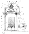
- FIG. 1 The device is initially shown in general form in FIG. 1, to which reference is first made.
- a stack of goods 3 conveyed by the latter is arranged on a carriageway 2 within a device frame 1.
- a roller 4 is mounted on which a plastic tube 5 made of stretchable material is wound with gussets.
- Stretchable material is understood to mean one that returns to the state it was in before stretching.
- the hose 5 located on the roll 4 with folded-in side edges is fed via deflection rollers 6 and drive rollers 7 to a threading device which consists of the area of the folded hose edges of vertically movably arranged guide elements 8, below which a separating device 9 and a welding device 10 are arranged.
- two roof-shaped double conveyor belts 11 are arranged on both sides of the frame, the upper receiving ends being located directly below the guide elements 8 in their lowered position.
- a pivot lever 18 is assigned to each double conveyor belt 11.
- Each swivel lever 18 lies somewhat inward of the associated double conveyor belt 11, seen in plan view.
- each spreading finger 13 is adjustable in the longitudinal and transverse directions to adapt to different dimensions of the stack of goods 3, a corresponding drive device is shown generally in FIG. 1 and denoted by 15.
- a drive roller 16 is assigned on the outside, which in FIG. 1 can be moved in a manner not shown in the direction of the spreading finger 13 into the active position shown in FIGS. 2, 9 and 11 and from this in FIGS. 1, 7 , 8 and 11 reproduced ineffective position can be moved radially outwards.
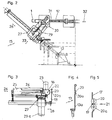
- Each spreading finger 13 is provided in its vertical web 13a, on which the tubular film is guided, with a recess 19 in which two rollers 20, 20a arranged one above the other are rotatably mounted.
- the rollers 20, 20a protrude in regions on the side facing the tubular film hood and the drive wheel 16, opposite the vertical surface 13a of the spreading finger 13.
- the rollers 20, 20a are arranged one above the other in such a way that there is a small distance between them, which is denoted by 21, such that the rollers 20, 20a are not in contact with one another.
- rollers 20 and 20a are arranged side by side in the recess 19, or a correspondingly wider roller can also be used in each case.
- the spreading finger surface 13a is advantageously bent inwards at the lower edge of the recess 19 (FIG. 5).
- the arrangement of the rollers 20, 20a is preferably such that the rollers are arranged symmetrically to a horizontal plane containing the axis of rotation 22 of the drive wheel 16. This has the advantage that when the drive wheel 16 is moved radially inward, the drive wheel is centered by the rollers 20, 20a and evenly comes into contact with the rollers 20, 20a or touches the area between the stretch film tube.
- the inventive design of the adjustability of the spreading fingers 13 and drive wheels 16 is shown in FIGS. 2 and 3.
- the drive wheel 16, which is provided with a drive motor 23, is arranged on a support arm 24 which, via a piston / cylinder unit 25, enables radial movement in the direction of the arrow 26, ie radially to the associated spreading finger 13 or away from it.
- the support arm 24 with the piston / cylinder unit 25 is arranged on a support element 27 on which the relevant one Spreading finger 13 is arranged, which is movable relative to the support member 27 in the radial direction (arrow 28).
- a spindle drive 29a is arranged on the support element 27, which enables the spreading finger 13 to be extended in the radial direction.
- a piston / cylinder unit 29 is arranged on the support element 27 itself, which in turn is fastened to a fastening element 30 which is connected to a piston / cylinder unit 31 which is fixed to the slide 12 at the other end.
- This configuration enables the following movements: First, the carriage 12 can be moved vertically in the frame 1 in the vertical direction, furthermore a displacement in the direction of the arrow 32 of the fastening element 30 is possible, and accordingly also the spreading finger 13 and the drive wheel 16 .
- the process sequence with a device according to the invention is as follows:
- the flat-lying stretch film tube 5 is threaded through the drive rollers 7 via the guide elements 8, which are in the lowered position when the machine is started.
- each folded edge of the hose is passed between a double conveyor belt 11, which causes the hose to be opened (FIG. 6).
- the drive of the drive rollers 7 and the double conveyor belts 11 are stopped and the spreading fingers 13 are inserted into the lower end of the hose. After retraction, the spreading fingers 13 are stopped, so that the tube wraps around the spreading fingers 13 at its four corners.
- the drive rollers 16 are moved up to the spreading fingers 13 and put into operation, namely together with the drive rollers 7 and the double conveyor belts 11, until the length of the stack 3 corresponding to the height of the stack 3 has been placed in bellows-like fashion in waves like bellows.
- proper folding is achieved in that the drive wheels 16 lie flat against the tubular film 5 by the rollers 20, 20a on the spreading fingers 13.
- the drive rollers 7, the double conveyor belts 11 and the drive rollers 16 are then stopped again (FIG. 7).
- the separating and welding devices 9 and 10 are actuated.
- the double conveyor belts 11 are actuated again and, at the same time, the pivoting levers 18 are pivoted downward, whereby the folded hose wheels are pushed out of the receiving ends of the double conveyor belts.
- the spreading fingers 13 are moved into the stretching position shown in FIG. 1 and the drive rollers 16 are moved radially outward.
- the stack of goods 3 is raised beyond the carriageway 2 and the chains, not shown, are driven in such a way that the carriage 12 with the spreading fingers 13 coupled therewith and on this in Stretching position of the hose 5 of the hood 17 located in waves can be moved downwards along the stack.
- the upper closed end of the hood 17 formed by the welding lies on the surface of the stack 3, so that upon further covering of the corrugated hood 17 wave after wave pulls up and rests on the side surface of the stack 3 according to its release from the stretching position (see Fig. 8). This ensures that the rollers 20, 20a pull it up correctly on the spreading fingers 13.
- the drive wheels 16 can be moved up to the spreading fingers 13 and put into operation during the pulling-over, in such a way that the film hood is stretched in the vertical direction by a corresponding relative movement.
- the drive rollers 16 In the lower region of the stack, the drive rollers 16 then remain in their contact position, being driven or stopped in order to bring about a certain clamping of the hood 17 between the drive rollers 16 and spreading fingers 13.
- the downward speed of the carriages 12 is then increased in the lower region of the stack of goods, in particular when the carriages 12 are in the region of the lower corner edges of the stack of goods (FIG. 9).
- the spreading fingers 13 are possibly moved radially inward with the drive rollers 16, and indeed at a greater speed than the downward speed of the slides 12 in the lower region of the stack of goods. Then the drive rollers 16 and the spreader rods 13 are moved radially outward, so that the hood 17 is also released in its open edge area located below the stack 3. Due to the restoring force of the stretch film hood 17, this is kicked around the lower edge surface of the base of the stack 3 in such a way that a good connection of the base of the stack 3 with the objects stacked on it is ensured.
- the increased speed of the downward movement of the carriage 12 in the lower stack area and the even greater Inward movement of the spreading fingers 13 underneath the stack ensures that the hood 17 remains below the stack of goods 2 and does not slip beyond the lower corner edges into the side area.
- the coated stack of goods 3 can then be moved out of the frame 1 after being lowered onto the carriageway 2 and a new stack of goods can be inserted, whereupon the process sequence begins again.
Landscapes
- Engineering & Computer Science (AREA)
- Mechanical Engineering (AREA)
- Pile Receivers (AREA)
- Basic Packing Technique (AREA)
- Containers And Plastic Fillers For Packaging (AREA)
- Stacking Of Articles And Auxiliary Devices (AREA)
- Making Paper Articles (AREA)
- Folding Of Thin Sheet-Like Materials, Special Discharging Devices, And Others (AREA)
Abstract
Description
Die Erfindung betrifft eine Vorrichtung zur Bildung eines Gutstapels durch Verbinden und Umhüllen eines auf einer Unterlage insbesondere aus einer Mehrzahl von Gegenständen gebildeten Stapels mittels Stretchfolie mit einer Stretchfolienschlauchabzugseinrichtung, einer dieser nachgeordneten Aufspreizeinrichtung zum Aufspreizen des freien Schlauchendes, einer Trenn- und Schweißeinrichtung zum Abrennen eines Schlauchabschnittes und Bilden einer Stretchaube und mit einer Haubenüberzieheinrichtung, welche wenigtens vier in Horizontal- und Vertikalrichtung bewegbare Spreizfinger aufweist, die die Haube in den vier Eckbereichen faltenbalgartig zusammengelegt aufnehmen, wobei jedem Spreizfinger an der Außenseite eine gegenüber dem jeweiligen Spreizfinger verstellbare Antriebsrolle zugeordnet ist, mittels derer die Haube in die faltenbalgartige Position gebracht und beim Überziehen durch Relativbewegung in vertikaler Überziehrichtung gereckt wird, wobei der jeweilige Spreizfinger und die zugeordnete Antriebsrolle an einem gemeinsamen vertikal beweglichen Schlitten angeordnet sind. Die Erfindung betrifft darüber hinaus ein Verfahren mit einer gattungsgemäßen Vorrichtung.The invention relates to a device for forming a stack of goods by connecting and wrapping a stack formed on a base, in particular from a plurality of objects, by means of stretch film with a stretch film hose pull-off device, a spreading device downstream of this for spreading the free hose end, a separating and welding device for severing a hose section and forming a stretch hood and with a hood covering device which has at least four spreading fingers which can be moved in the horizontal and vertical directions and which receive the hood folded together in the four corner regions in a bellows-like manner, with each spreading finger being assigned on the outside a drive roller which is adjustable relative to the respective spreading finger, by means of which the hood is brought into the bellows-like position and is stretched when pulled over by relative movement in the vertical pulling direction, the respective spreading finger and di e assigned drive roller are arranged on a common vertically movable carriage. The invention also relates to a method with a generic device.
Eine solche Vorrichtung und ein solches Verfahren wird von der Anmelderin benutzt und ist darüber hinaus in der nicht vorveröffentlichten DE-P 41 18 642 beschrieben. Eine solche Vorrichtung weist zwar gegenüber ähnlichen Vorrichtungen (z.B. EP 0 344 815 A1) bereits Vorteile auf, da diese Vorrichtung aufgrund der Ausbildung ihrer Spreizfinger und der zugeordneten Antriebsrollen besonders kompakt ausgebildet ist und außerdem auf relativ einfache Weise an unterschiedliche Gutstapelgrößen angepaßt werden kann.Such a device and such a method is used by the applicant and is also described in the unpublished DE-P 41 18 642. Such Although the device already has advantages over similar devices (for example EP 0 344 815 A1), since this device is of particularly compact design due to the design of its spreading fingers and the associated drive rollers and can also be adapted in a relatively simple manner to different stack sizes.
Es hat sich jedoch herausgestellt, daß die bekannte Vorrichtung beim faltenbalgartigen Zusammenlegen der Haubenränder vor dem Überziehen und insbesondere beim Auseinanderziehen während des Überziehens und beim gleichzeitigen Stretchen in Vertikalrichtung noch nicht einwandfrei arbeitet. Beim faltenbalgartigen Zusammenlegen der Seitenränder kann es nämlich zu unkontrollierten Überlappungen der Haubenseitenränder im Bereich der äußeren Flächen der Spreizfinger kommen, was beim Überziehen bzw. dadurch verursachten Auseinanderziehen und insbesondere auch beim zusätzlichen Vertikalstretchen während des Überziehens der Haube über den Gutstapel dazu führt, daß die Haube insbesondere in den Eckbereichen reißt, so daß keine einwandfreie Verpackung gebildet werden kann. Dies ist sowohl auf unterschiedliche Streckkräfte in der Haube als auch auf die Überlappung der zusammengefalteten Randbereiche zurückzuführen.It has been found, however, that the known device does not yet function properly when the hood edges are folded up like a bellows before being pulled over, and in particular when pulled apart during pulling and when stretching at the same time in the vertical direction. When the side edges are folded like a bellows, uncontrolled overlaps of the hood side edges in the area of the outer surfaces of the spreading fingers can occur, which when the cover is pulled or pulled apart, and in particular also when the hood is pulled vertically over the stack of goods, leads to the hood tears especially in the corner areas, so that no perfect packaging can be formed. This is due both to different stretching forces in the hood and to the overlapping of the folded edge areas.
Darüber hinaus ist bei der bekannten Vorrichtung von Nachteil, daß eine Anpassung an unterschiedliche Gutstapelgrundflächengrößen nur aufwendig möglich ist, da dazu eine manuelle Einstellung der entsprechenden Elemente notwendig ist.In addition, a disadvantage of the known device is that it can be adapted to different good stack base sizes is only possible with great effort, since this requires a manual setting of the corresponding elements.
Aufgabe der Erfindung ist die Schaffung einer Lösung, mit der eine einwandfreie Umhüllung des Gutstapels mit einer Stretchfolienhaube ermöglicht wird, wobei in Ausgestaltung zusätzlich auch eine einfache Anpassung an unterschiedliche Gutstapelgrundflächengrößen möglich sein soll.The object of the invention is to provide a solution with which a perfect wrapping of the stack of goods with a stretch film hood is made possible, in addition to which a simple adaptation to different stack sizes of the stack should also be possible.
Diese Aufgabe wird mit einer Vorrichtung der eingangs bezeichneten Art erfindungsgemäß dadurch gelöst, daß jeder Spreizfinger mit einer Aussparung versehen ist, in der zwei übereinander angeordnete Rollen drehbar gelagert sind wobei die Rollen bereichsweise auf der der Haube und dem Antriebsrad zugewandten Seite gegenüber der Spreizfingerfläche hervorstehen und das Antriebsrad in nach innen verfahrener Position mit den Rollen unter Zwischenschaltung der Folienhaube in Kontakt steht.This object is achieved according to the invention with a device of the type mentioned in the introduction in that each spreading finger is provided with a recess in which two rollers arranged one above the other are rotatably mounted, the rollers projecting in regions on the side facing the hood and the drive wheel opposite the spreading finger surface and the drive wheel is in contact with the rollers in the inwardly moved position with the interposition of the film hood.
Mit dieser Vorrichtung ist es möglich, einen Gutstapel einwandfrei mit einer Stretchfolienhaube zu verpacken, ohne daß es beim Verpackungsvorgang zu Beschädigungen der Folienhaube kommt. Durch die Ausgestaltung der Spreizfinger ist nämlich gewährleistet, daß die Antriebsräder beim faltenbalgartigen Zusammenlegen der Seitenränder der Haube und auch beim vertikalen Stretchen der Haube während des Überziehens durch Aufbringung einer entsprechenden Relativbewegung in vertikaler Richtung durch die Antriebsräder ein flächiger Kontakt zwischen dem Antriebsrad und der jeweiligen Haubenfläche erfolgt, so daß eine ungleichmäßige Stretchung und insbesondere auch eine Überlappung der in Falten gelegten Ränder zuverlässig vermieden wird. Die Haube wird nämlich durch die Ausbildung der Rollen an den Spreizfingern zwangsläufig so geführt, daß ein entsprechender flächiger Kontakt mit der jeweiligen Antriebsrolle gewährleistet ist. Es kann dadurch zuverlässig auch eine Überstretchung von Folienhaubenbereichen vermieden werden, so daß eine einwandfreie gleichmäßige Stretchung gewährleistet ist. Darüber hinaus ist zudem beim Abziehen der Haubenseitenränder von den Spreizfingern ein einwandfreies ungehindertes Abgleiten möglich, wenn die jeweiligen Antriebsräder außer Eingriff mit den Spreizfingern sind.With this device it is possible to properly pack a stack of goods with a stretch film hood without causing damage to the film hood during the packaging process. The design of the spreading fingers ensures that the drive wheels when the bellows are folded together like the side edges of the hood and also when the hood is stretched vertically while being pulled over by applying a corresponding relative movement in the vertical direction by the drive wheels, there is a flat contact between the drive wheel and the respective hood surface, so that uneven stretching and in particular an overlap of the folded edges is reliably avoided. The hood is inevitably guided by the formation of the rollers on the spreading fingers so that a corresponding flat contact with the respective drive roller is guaranteed. As a result, it is also possible to reliably avoid overstretching of film hood areas, so that perfect, uniform stretching is ensured. In addition, when pulling off the hood side edges from the spreading fingers, it is possible to slide freely without hindrance if the respective drive wheels are out of engagement with the spreading fingers.
In vorteilhafter Ausgestaltung der Erfindung ist vorgesehen, daß die Rollen symmetrisch zu einer die Drehachse des Antriebsrades enthaltenden Horizontalebene angeordnet sind. Bei dieser Ausgestaltung ist zusätzlich gewährleistet, daß beim radialen Nachinnenverfahren des Antriebsrades in Richtung zum jeweiligen Spreizfinger automatisch eine entsprechende Zentrierung des Antriebsrades erfolgt, d.h. dieses wird automatisch entsprechend symmetrisch zu den beiden Rollen des betreffenden Spreizfingers angeordnet, so daß ein einwandfreier Kontakt und damit eine flächige Anlage des Folienschlauchrandes gewährleistet ist.In an advantageous embodiment of the invention it is provided that the rollers are arranged symmetrically to a horizontal plane containing the axis of rotation of the drive wheel. This configuration additionally ensures that when the drive wheel is moved radially inward in the direction of the respective spreading finger, the drive wheel is appropriately centered, ie this is automatically arranged symmetrically with respect to the two rollers of the spreading finger in question, so that a perfect contact and thus a flat contact of the film tube edge is guaranteed.
Vorteilhaft sieht die Erfindung auch vor, daß jeweils wenigstens zwei Rollen nebeneinander in die Aussparung angeordnet sind. Es ist dadurch möglich, eine entsprechend noch größere Anlagefläche für die Folienhaube zur Verfügung zu stellen.The invention also advantageously provides that at least two rollers are arranged side by side in the recess. This makes it possible to provide a correspondingly larger contact surface for the film hood.
Um eine Einklemmung des Folienschlauches zu verhindern, ist vorteilhaft vorgesehen, daß am unteren Rand der Aussparung die Spreizfingerfläche nach innen abgekantet ist.In order to prevent the film tube from being pinched, it is advantageously provided that the spreading finger surface is bent inwards at the lower edge of the recess.
In besonders vorteilhafter Ausgestaltung der Erfindung ist vorgesehen, daß am jeweiligen vertikal beweglichen Schlitten ein Tragelement angeordnet ist, das das Antriebsrad und den Spreizfinger trägt und das rechtwinklig zur radialen Auslenkrichtung der Spreizfinger verschiebbar ist. Durch diese zusätzliche Ausgestaltung ist es möglich, die Vorrichtung auf einfachste Weise auch an unterschiedliche Gutstapelgrundflächengrößen anzupassen, wobei die entsprechende Verstellung dann automatisch durch die Steuerung der Vorrichtung erfolgt.In a particularly advantageous embodiment of the invention it is provided that a support element is arranged on the respective vertically movable slide, which carries the drive wheel and the spreading finger and which can be displaced at right angles to the radial deflection direction of the spreading finger. This additional configuration makes it possible to adapt the device in a very simple manner to different good stack base sizes, the corresponding adjustment then being carried out automatically by the control of the device.
Vorteilhaft ist auch vorgesehen, daß das Tragelement zusätzlich entlang des Schlittens verschiebbar ist. Dadurch ist eine noch bessere Anpassung an unterschiedliche Gutstapelgrößen möglich, ohne den Raumbedarf der Vorrichtung zu vergrößern.It is also advantageously provided that the support element is additionally displaceable along the carriage. This is an even better adaptation to different stack sizes possible without increasing the space requirement of the device.
Zur Lösung der eingangs gestellten Aufgabe sieht die Erfindung auch ein Verfahren zur Bildung eines Gutstapels nach dem Oberbegriff des Patentanspruches 6 mit einer vorgenannten Vorrichtung vor, das sich dadurch auszeichnet, daß die Haube im unteren Bereich des Stapels und beim Unterziehen unter den Gutstapel bei zeitweiser Einklemmung zwischen den Antriebsrädern und Spreizfingern mit erhöhter Überziehgeschwindigkeit gezogen wird.To achieve the object set forth in the invention, the invention also provides a method for forming a stack of goods according to the preamble of
Durch dieses Verfahren ist es möglich, eine einwandfreie feste Verpackung mit einer Stretchfolienhaube zu erzielen, da eine einwandfreie Festlegung der Folie auch an der Unterkante des Gutstapels gewährleistet ist. Durch die exakte Steuerung der Überziehgeschwindigkeit ist nämlich sichergestellt, daß die Haube sich am unteren Eckkantenbereich nicht wieder von der Unterkante hinaus zu den Seitenrändern wegziehen kann.This method makes it possible to achieve perfect, firm packaging with a stretch film hood, since the film is also fixed correctly on the lower edge of the stack of goods. Precise control of the pulling-over speed ensures that the hood at the lower corner edge area cannot pull away again from the lower edge to the side edges.
Dabei ist es vorteilhaft vorgesehen, daß beim Unterziehen der Haube unter den Gutstapel die einwärts gerichtete Geschwindigkeit größer ist als die Überziehgeschwindigkeit im unteren Bereich des Stapels. Durch diese Verfahrensführung wird eine noch verbesserte Verpackung gewährleistet.It is advantageously provided that when the hood is pulled under the stack of goods, the inward speed is greater than the pulling speed in the lower region of the stack. This procedure ensures an even better packaging.
Die Erfindung ist nachstehend anhand der Zeichnung beispielsweise näher erläutert. Diese zeigt in
- Fig. 1
- in vereinfachter Seitenansicht eine erfindungsgemäße Vorrichtung,
- Fig. 2
- in Draufsicht einen Eckbereich einer Vorrichtung mit Spreizfinger und Antriebsrad,
- Fig. 3
- eine Seitenansicht der Fig. 2 in Richtung des Pfeiles 33,
- Fig. 4
- einen Schnitt durch einen Spreizfinger nach Fig. 3,
- Fig. 5
- ein vergrößertes Detail des Spreizfingers nach Fig. 4 und in den
- Fig. 6 bis 11
- jeweils in vereinfachter Seitenansicht eine Vorrichtung nach Fig. 1 in verschiedenen Verfahrensstadien.
- Fig. 1
- a device according to the invention in a simplified side view,
- Fig. 2
- a top view of a corner area of a device with a spreading finger and drive wheel,
- Fig. 3
- 2 in the direction of arrow 33,
- Fig. 4
- 4 shows a section through an expanding finger according to FIG. 3,
- Fig. 5
- an enlarged detail of the spreading finger according to FIG. 4 and in the
- 6 to 11
- each in a simplified side view of a device according to FIG. 1 in different stages of the process.
In den Figuren sind durchgängig dieselben Bezugszeichen für gleiche Teile verwandt. Die Vorrichtung ist zunächst in allgemeiner Form in Fig. 1 dargestellt, auf die zunächst Bezug genommen wird.Throughout the figures, the same reference numerals are used for the same parts. The device is initially shown in general form in FIG. 1, to which reference is first made.
Innerhalb eines Vorrichtungsgestells 1 ist auf einer Fahrbahn 2 ein von dieser angeförderter Gutstapel 3 angeordnet.A stack of
Im Gestell 1 ist eine Rolle 4 gelagert, auf der ein Kunststoff-Schlauch 5 aus stretchfähigem Material mit Seitenfalten aufgewickelt ist. Unter stretchfähigem Material wird ein solches verstanden, das nach Reckung in seinen vor der Reckung eingenommenen Zustand zurückkehrt. Der mit eingefalteten Seitenrändern auf der Rolle 4 befindliche Schlauch 5 wird über Umlenkrollen 6 und Antriebsrollen 7 einer Einfädeleinrichtung zugeführt, die aus dem Bereich der gefalteten Schlauchränder vertikal beweglich angeordneten Leitelementen 8 besteht, unterhalb welcher eine Trenneinrichtung 9 sowie eine Schweißeinrichtung 10 angeordnet sind.In the
Unterhalb der Leitelemente 8 sind auf beiden Seiten des Gestells zwei dachförmige angeordnete Doppelförderbänder 11 angeordnet, wobei die oberen Aufnahmeenden unmittelbar unterhalb der Leitelemente 8 in deren abgesenkter Stellung befindlich sind.Below the
Jedem Doppelförderband 11 ist ein Schwenkhebel 18 zugeordnet. Jeder Schwenkhebel 18 liegt dabei in Draufsicht gesehen etwas einwärts des zugeordneten Doppelförderbandes 11.A
Im Gestell 1 sind in der Nähe der vier Ecken desselben endlos umlaufende Ketten gelagert, in der Zeichnung nicht dargestellt, an denen parallel zur Fahrbahnrichtung je ein Schlitten 12 jeweils mit zwei vertikalen Spreizfingern 13 mit Kopf 14 befestigt ist, wobei diese Befestigung im einzelnen noch näher beschrieben wird. Jeder Spreizfinger 13 ist in Längs- und Querrichtung zur Anpassung an verschiedene Abmessungen des Gutstapels 3 verstellbar, eine entsprechende Antriebseinrichtung ist in Fig. 1 allgemein dargestellt und mit 15 bezeichnet. Am oberen Ende jedes Spreizfingers 13 ist außen eine Antriebsrolle 16 zugeordnet, die in Fig. 1 in nicht näher dargestellter Weise in Richtung zum Spreizfinger 13 in die in den Figuren 2, 9 und 11 wiedergegebene Wirkstellung beweglich und aus dieser in den Figuren 1, 7, 8 und 11 wiedergegebene unwirksame Stellung radial nach außen bewegbar ist.In
Die erfindungsgemäße Ausgestaltung der Spreizfinger geht am besten aus den Figuren 4 und 5 hervor. Jeder Spreizfinger 13 ist in seinem vertikalen Steg 13a, an dem die Schlauchfolie geführt ist, mit einer Aussparung 19 versehen, in der zwei übereinander angeordnete Rollen 20,20a drehbar gelagert sind. Dabei stehen die Rollen 20,20a bereichsweise auf der der Schlauchfolienhaube und dem Antriebsrad 16 zugewandten Seite gegenüber der vertikalen Fläche 13a des Spreizfingers 13 hervor. Die Rollen 20,20a sind derart übereinander angeordnet, daß zwischen ihnen ein geringer Abstand besteht, der mit 21 bezeichnet ist, derart, daß die Rollen 20,20a nicht miteinander in Kontakt stehen. Es kann dabei vorgesehen sein, daß jeweils wenigstens zwei Rollen 20 bzw. 20a nebeneinander in der Aussparung 19 angeordnet sind oder es kann auch jeweils eine entsprechend breitere Rolle eingesetzt werden. Um eine Einklemmung der Folie zu vermeiden, ist am unteren Rand der Aussparung 19 vorteilhaft die Spreizfingerfläche 13a bereichsweise nach innen abgekantet (Fig. 5).The configuration of the spreading fingers according to the invention can best be seen from FIGS. 4 and 5. Each spreading
Die Anordnung der Rollen 20,20a ist, wie am besten aus Fig. 3 hervorgeht, bevorzugt so getroffen, daß die Rollen symmetrisch zu einer die Drehachse 22 des Antriebsrades 16 enthaltenden Horizontalebene angeordnet sind. Dies hat den Vorteil, daß beim radialen Nachinnenverfahren des Antriebsrades 16 das Antriebsrad von den Rollen 20,20a zentriert wird und gleichmäßig mit den Rollen 20,20a in Kontakt kommt bzw. den dazwischenbefindlichen Stretchfolienschlauch flächig berührt.3, the arrangement of the
Die erfindungsgemäße Ausbildung der Verstellbarkeit der Spreizfinger 13 und Antriebsräder 16 ist in den Fig. 2 und 3 dargestellt. Das Antriebsrad 16, das mit einem Antriebsmotor 23 versehen ist, ist an einem Tragarm 24 angeordnet, der über eine Kolben-/Zylindereinheit 25 eine radiale Bewegung in Richtung des Pfeiles 26 ermöglicht, d.h. radial zum zugeordneten Spreizfinger 13 bzw. von diesem weg. Dabei ist der Tragarm 24 mit der Kolben-/Zylindereinheit 25 an einem Tragelement 27 angeordnet, an dem auch der betreffende Spreizfinger 13 angeordnet ist, welcher gegenüber dem Tragelement 27 in radialer Richtung (Pfeil 28) beweglich ist. Dazu ist ein Spindelantrieb 29a am Tragelement 27 angeordnet, der ein Ausfahren des Spreizfingers 13 in radialer Richtung ermöglicht.The inventive design of the adjustability of the spreading
Am Tragelement 27 selbst ist eine Kolben-/Zylindereinheit 29 angeordnet, die ihrerseits an einem Befestigungselement 30 befestigt ist, welches mit einer Kolben-/Zylindereinheit 31 verbunden ist, die am anderen Ende am Schlitten 12 festgelegt ist. Durch diese Ausgestaltung sind folgende Bewegungen möglich: Zunächst läßt sich der Schlitten 12 im Gestell 1 in vertikaler Richtung in der Höhe verfahren, darüber hinaus ist eine Verschiebung in Richtung des Pfeiles 32 des Befestigungselementes 30 möglich und damit entsprechend auch des Spreizfingers 13 und des Antriebsrades 16.A piston /
Mit der Kolben-/Zylindereinheit 29 ist eine Verschiebung des Tragelementes 27 und damit des Spreizfingers 13 rechtwinklig zur radialen Auslenkrichtung 26 des Spreizfingers möglich (Pfeil 33). Aufgrund dieser Verschiebbarkeit ist es möglich, die Vorrichtung auch für Gutstapel einzusetzen, die unterschiedliche Grundflächen aufweisen.With the piston /
Der Verfahrensablauf mit einer erfindungsgemäßen Vorrichtung ist der folgende:
Der flachliegende Stretchfolienschlauch 5 wird durch die Antriebsrollen 7 über die Leitelemente 8 eingefädelt, die sich beim Anfahren der Maschine in abgesenkter Stellung befinden. Am unteren Ende der Leitelemente wird jeder eingefaltete Rand des Schlauches zwischen ein Doppelförderband 11 geleitet, wodurch das Öffnen des Schlauches besorgt wird (Fig. 6). Nachdem das untere Ende des Schlauches ein Stück aus den Doppelförderbändern 11 herausgelaufen ist, werden der Antrieb der Antriebsrollen 7 sowie die Doppelförderbänder 11 gestoppt und die Spreizfinger 13 werden in das untere Schlauchende eingefahren. Nach dem Einfahren werden die Spreizfinger 13 angehalten, so daß sich der Schlauch an seinen vier Ecken um die Spreizfinger 13 legt. Daraufhin werden die Antriebsrollen 16 an die Spreizfinger 13 herangefahren und in Betrieb gesetzt, und zwar zusammen mit den Antriebsrollen 7 und den Doppelförderbändern 11, bis die der Höhe des Stapels 3 entsprechende Länge Schlauch um die Spreizfinger 13 faltenbalgartig in Wellen gelegt worden sind. Dabei wird eine einwandfreie Faltenlegung dadurch bewirkt, daß die Antriebsräder 16 durch die Rollen 20,20a an den Spreizfingern 13 flächig an der Schlauchfolie 5 anliegen. Anschließend werden die Antriebsrollen 7, die Doppelförderbänder 11 und die Antriebsrollen 16 wieder gestoppt (Fig. 7). Die Trenn- und Schweißeinrichtungen 9 und 10 werden betätigt. Nach der Beendigung des Trenn- und Schweißvorganges werden die Doppelförderbänder 11 wieder betätigt und gleichzeitig die Schwenkhebel 18 abwärts geschwenkt, wodurch die gefalteten Schlauchräder aus den Aufnahmeenden der Doppelförderbänder herausgedrückt bzw. gezogen werden.The process sequence with a device according to the invention is as follows:
The flat-lying
Sobald der Schlauch von den Doppelförderbändern 11 freigegeben ist, werden die Spreizfinger 13 in die in Fig. 1 wiedergegebene Reckstellung bewegt und die Antriebsrollen 16 radial nach außen bewegt. Unmittelbar nach Einnahme der in Fig. 1 wiedergegebenen Reckstellung mit 17 bezeichneter Stretchfolienhaube wird der Gutstapel 3 über die Fahrbahn 2 hinaus angehoben und die nicht dargestellten Ketten werden angetrieben, derart, daß die Schlitten 12 sich mit den damit gekoppelten Spreizfingern 13 und dem auf diesen in Reckstellung in Wellen befindlichen Schlauch 5 der Haube 17 längs des Stapels abwärts bewegt werden. Dabei legt sich das obere verschlossene Ende der durch das Verschweißen gebildeten Haube 17 auf die Oberfläche des Stapels 3 auf, so daß beim weiteren Überziehen der gewellten Haube 17 sich Welle nach Welle aufzieht und entsprechend ihrer Freigabe aus der Reckstellung an die Seitenfläche des Stapels 3 anliegt (siehe Fig. 8). Dabei wird ein einwandfreies Aufziehen durch die Rollen 20,20a an den Spreizfingern 13 gewährleistet.As soon as the hose is released from the
Zur Vertikalstretchung der Folienhaube können während des Überziehens die Antriebsräder 16 an die Spreizfinger 13 herangefahren und in Betrieb gesetzt werden, derart, daß die Folienhaube in vertikaler Richtung durch eine entsprechende Relativbewegung gestretcht werden.For vertical stretching of the film hood, the
Im unteren Bereich des Stapels verbleiben dann die Antriebsrollen 16 in ihrer Kontaktposition, wobei sie angetrieben bzw. angehalten werden, um eine gewisse Einklemmung der Haube 17 zwischen Antriebsrollen 16 und Spreizfingern 13 zu bewirken. Dabei wird dann im unteren Bereich des Gutstapels die Abwärtsgeschwindigkeit der Schlitten 12 erhöht, insbesondere dann, wenn sich die Schlitten 12 im Bereich der unteren Eckkanten des Gutstapels befinden (Fig. 9).In the lower region of the stack, the
Ist der gesamte Gutstapel mit der Haube 17 überzogen (Fig. 10) werden die Spreizfinger 13 ggf. mit den Antriebsrollen 16 radial nach innen verfahren, und zwar mit einer größeren Geschwindigkeit als die Abwärtsgeschwindigkeit der Schlitten 12 im unteren Bereich des Gutstapels. Anschließend werden die Antriebsrollen 16 und die Spreizstangen 13 radial nach außen bewegt, so daß die Haube 17 auch in ihrem offenen, sich unterhalb des Stapels 3 befindlichen Randbereich freigegeben wird. Aufgrund der Rückstellkraft der Stretchfolienhaube 17 wird diese um die untere Randfläche der Unterlage des Stapels 3 herumgestretcht, derart, daß eine gute Verbindung der Unterlage des Stapels 3 mit den auf dieser gestapelten Gegenständen gewährleistet ist. Dabei wird durch die vergrößerte Geschwindigkeit der Abwärtsbewegung der Schlitten 12 im unteren Stapelbereich und die noch größere Einwärtsbewegung der Spreizfinger 13 unter den Stapel sicher gewährleistet, daß die Haube 17 unterhalb des Gutstapels 2 verbleibt und nicht über die unteren Eckkanten hinaus in den Seitenbereich hinausrutscht.If the entire stack of goods is covered with the hood 17 (FIG. 10), the spreading
Der übergezogene Gutstapel 3 kann anschließend nach Absenken auf die Fahrbahn 2 aus dem Gestell 1 herausgefahren und ein neuer Gutstapel eingefahren werden, worauf der Verfahrensablauf von neuem beginnt.The coated stack of
Natürlich sind die beschriebenen Ausführungsbeispiele noch in vielfacher Weise abzuändern, ohne den Grundgedanken der Erfindung zu verlassen. So sind insbesondere die einzelnen Verstellmechanismen nicht auf Kolben-/Zylindereinheiten beschränkt, hier können auch andere bekannte Verstellmechanismen Einsatz finden und dgl. mehr.Of course, the exemplary embodiments described can be modified in many ways without departing from the basic idea of the invention. In particular, the individual adjustment mechanisms are not limited to piston / cylinder units; other known adjustment mechanisms can also be used here and the like. More.
Claims (8)
dadurch gekennzeichnet,
daß jeder Spreizfinger (13) mit einer Aussparung (19) versehen ist, in der zwei übereinander angeordnete Rollen (20,20a) drehbar gelagert sind, wobei die Rollen (20,20a) bereichsweise auf der der Haube (17) und dem Antriebsrad (16) zugewandten Seite gegenüber der Spreizfingerfläche (13a) hervorstehen und das Antriebsrad (16) in nach innen verfahrener Position mit den Rollen (20,20a) unter Zwischenschaltung der Folienhaube (17) in Kontakt steht.Device for forming a stack of goods by connecting and wrapping a stack formed on a base, in particular from a plurality of objects, by means of stretch film with a stretch film hose pull-off device, a spreading device downstream of this for spreading the free hose end, a separating and welding device for separating a hose section and forming a stretch hood and with a hood covering device which has at least four spreading fingers which can be moved in the horizontal and vertical directions and which accommodate the hood in the four corner regions in a bellows-like manner, wherein each spreading finger is assigned on the outside a drive roller which is adjustable relative to the respective spreading finger and by means of which the hood is inserted into the brought bellows-like position and stretched when pulling by relative movement in the vertical pulling direction, the respective spreading finger and the associated drive roller le are arranged on a common vertically movable slide,
characterized,
that each spreading finger (13) is provided with a recess (19) in which two rollers (20, 20a) arranged one above the other are rotatably mounted, the rollers (20, 20a) protrude in areas on the side facing the hood (17) and the drive wheel (16) opposite the spreading finger surface (13a) and the drive wheel (16) in an inwardly moved position with the rollers (20, 20a) with the interposition of the film hood (17) in Contact is there.
dadurch gekennzeichnet,
daß die Rollen (20,20a) symmetrisch zu einer die Drehachse (22) des Antriebsrades (16) enthaltenden Horizontalebene angeordnet sind.Device according to claim 1,
characterized,
that the rollers (20, 20a) are arranged symmetrically to a horizontal plane containing the axis of rotation (22) of the drive wheel (16).
dadurch gekennzeichnet,
daß jeweils wenigstens zwei Rollen (20,20a) nebeneinander in der Aussparung (19) angeordnet sind.Device according to claim 1 or 2,
characterized,
that at least two rollers (20, 20a) are arranged side by side in the recess (19).
dadurch gekennzeichnet,
daß am unteren Rand der Aussparung (19) die Spreizfingerfläche (13a) nach innen abgekantet ist.Device according to claim 1 or one of the following,
characterized,
that at the lower edge of the recess (19) the spreading finger surface (13a) is folded inwards.
dadurch gekennzeichnet,
daß am jeweiligen vertikal beweglichen Schlitten (12) ein Tragelement (27) angeordnet ist, das das Antriebsrad (16) und den Spreizfinger (13) trägt und das rechtwinklig (Pfeil 33) zur radialen Auslenkrichtung (Pfeil 26) der Spreizfinger (13) verschiebbar ist.Device according to claim 1 or one of the following,
characterized,
that on the respective vertically movable carriage (12) a support element (27) is arranged, which carries the drive wheel (16) and the spreading finger (13) and the right angle (arrow 33) for the radial deflection direction (arrow 26) of the spreading fingers (13) is displaceable.
dadurch gekennzeichnet,
daß das Tragelement (27) zusätzlich entlang des Schlittens (12) verschiebbar ist.Device according to claim 1 or one of the following,
characterized,
that the support element (27) is additionally displaceable along the carriage (12).
dadurch gekennzeichnet,
daß die Haube im unteren Bereich des Stapels und beim Unterziehen unter den Gutstapel bei zeitweiser Einklemmung zwischen den Antriebsrädern und Spreizfingern mit erhöhter Überziehgeschwindigkeit gezogen wird.Method of forming a stack of goods by connecting and wrapping a stack formed on a base, in particular from a plurality of objects, by means of stretch film, a stretch film tube being pulled off a roll above the stack, opened and cut off and closed at the upper end in accordance with the height of the stack to be wrapped closed a hood, the hood folded like a bellows and then stretched horizontally on a larger plan than that of the stack and then pulled initially from the upper edges of the stack over this and released from its stretched position to rest against the stack, the stretch film hood when pulling over the stack is additionally stretched in the vertical pulling direction with a device according to claim 1 or one of the following,
characterized,
that the hood in the lower area of the stack and when pulling under the stack of goods with occasional jamming is pulled between the drive wheels and spreading fingers with increased pulling speed.
dadurch gekennzeichnet,
daß beim Unterziehen der Haube unter den Gutstapel die einwärts gerichtete Geschwindigkeit größer ist als die Überziehgeschwindigkeit im unteren Bereich des Stapels.Method according to claim 7,
characterized,
that when the hood is pulled under the stack of goods, the inward speed is greater than the pulling speed in the lower region of the stack.
Applications Claiming Priority (2)
| Application Number | Priority Date | Filing Date | Title |
|---|---|---|---|
| DE4211297 | 1992-04-03 | ||
| DE4211297A DE4211297A1 (en) | 1992-04-03 | 1992-04-03 | Device and method for forming a stack of goods |
Publications (3)
| Publication Number | Publication Date |
|---|---|
| EP0564971A2 true EP0564971A2 (en) | 1993-10-13 |
| EP0564971A3 EP0564971A3 (en) | 1993-12-08 |
| EP0564971B1 EP0564971B1 (en) | 1997-05-07 |
Family
ID=6456044
Family Applications (1)
| Application Number | Title | Priority Date | Filing Date |
|---|---|---|---|
| EP93105325A Expired - Lifetime EP0564971B1 (en) | 1992-04-03 | 1993-03-31 | Device and method for making a stack of articles |
Country Status (3)
| Country | Link |
|---|---|
| EP (1) | EP0564971B1 (en) |
| AT (1) | ATE152682T1 (en) |
| DE (2) | DE4211297A1 (en) |
Cited By (6)
| Publication number | Priority date | Publication date | Assignee | Title |
|---|---|---|---|---|
| EP1184281A1 (en) * | 2000-08-09 | 2002-03-06 | Kl- Lachenmeier A/S | Method an apparatus for packaging objects |
| EP1275582A1 (en) * | 2001-07-11 | 2003-01-15 | Maschinenfabrik Möllers GmbH | Apparatus for wrapping a stack of products in a stretchable foil cover |
| US6865865B2 (en) * | 2001-01-25 | 2005-03-15 | Msk-Verpackungs-Systeme Gesellschaft Mit Beschrankter Haftung | Apparatus for wrapping a stack of objects |
| EP2623422A1 (en) * | 2012-02-01 | 2013-08-07 | Samsung Electronics Co., Ltd | Shrink packing system |
| NL2017863B1 (en) * | 2016-11-24 | 2018-06-01 | F3 Design B V | Packaging machine for applying a foil to an object to be packaged |
| US11827392B2 (en) | 2020-05-14 | 2023-11-28 | Signode Industrial Group Llc | Stretch-hood machine |
Families Citing this family (2)
| Publication number | Priority date | Publication date | Assignee | Title |
|---|---|---|---|---|
| DE20109692U1 (en) * | 2001-06-13 | 2002-10-24 | Beumer Maschf Gmbh & Co Kg | Device for wrapping general cargo by means of a stretch film hood |
| EP1266828B1 (en) | 2001-06-13 | 2005-05-04 | Beumer Maschinenfabrik GmbH & Co. KG | Method and apparatus for wrapping stacks of articles in a stretchable foil cover or sleeve |
Citations (5)
| Publication number | Priority date | Publication date | Assignee | Title |
|---|---|---|---|---|
| FR2230549A1 (en) * | 1973-05-23 | 1974-12-20 | Applic Thermiques | Machine for packing an object in a plastic sleeve - compresses sleeve into bellows form before passing object through |
| DE9001321U1 (en) * | 1990-02-06 | 1990-04-12 | Develog, Reiner Hannen & Cie, Corgemont, Ch | |
| DE9104072U1 (en) * | 1991-04-04 | 1991-06-20 | Develog, Reiner Hannen & Cie, Courtelary, Ch | |
| DE4103384A1 (en) * | 1990-02-06 | 1991-08-08 | Hannen Reiner Develog | Machine for wrapping goods in elastic film - has stretching frame which maintains tension of film as goods are wrapped |
| EP0461667A1 (en) * | 1990-06-15 | 1991-12-18 | Bernhard Beumer Maschinenfabrik KG | Method and apparatus for wrapping products in stretchable film |
Family Cites Families (2)
| Publication number | Priority date | Publication date | Assignee | Title |
|---|---|---|---|---|
| DE58900904D1 (en) * | 1988-06-03 | 1992-04-09 | Beumer Maschf Bernhard | METHOD AND DEVICE FOR COVERING PIECES OF GOODS, IN PARTICULAR STACKS OF GOODS, WITH A STRETCH FILM HOOD. |
| DE4037105C1 (en) * | 1990-11-22 | 1992-03-05 | Brega Verpackungsmaschinen-Anwendungstechnik Gmbh, 5884 Halver, De | Stretch film packaging machine - incorporates rollers running at different speeds for stretching effect |
-
1992
- 1992-04-03 DE DE4211297A patent/DE4211297A1/en not_active Withdrawn
-
1993
- 1993-03-31 AT AT93105325T patent/ATE152682T1/en active
- 1993-03-31 EP EP93105325A patent/EP0564971B1/en not_active Expired - Lifetime
- 1993-03-31 DE DE59306365T patent/DE59306365D1/en not_active Expired - Fee Related
Patent Citations (5)
| Publication number | Priority date | Publication date | Assignee | Title |
|---|---|---|---|---|
| FR2230549A1 (en) * | 1973-05-23 | 1974-12-20 | Applic Thermiques | Machine for packing an object in a plastic sleeve - compresses sleeve into bellows form before passing object through |
| DE9001321U1 (en) * | 1990-02-06 | 1990-04-12 | Develog, Reiner Hannen & Cie, Corgemont, Ch | |
| DE4103384A1 (en) * | 1990-02-06 | 1991-08-08 | Hannen Reiner Develog | Machine for wrapping goods in elastic film - has stretching frame which maintains tension of film as goods are wrapped |
| EP0461667A1 (en) * | 1990-06-15 | 1991-12-18 | Bernhard Beumer Maschinenfabrik KG | Method and apparatus for wrapping products in stretchable film |
| DE9104072U1 (en) * | 1991-04-04 | 1991-06-20 | Develog, Reiner Hannen & Cie, Courtelary, Ch |
Cited By (10)
| Publication number | Priority date | Publication date | Assignee | Title |
|---|---|---|---|---|
| EP1184281A1 (en) * | 2000-08-09 | 2002-03-06 | Kl- Lachenmeier A/S | Method an apparatus for packaging objects |
| US7040076B2 (en) | 2000-08-09 | 2006-05-09 | Lachenmeier A/S | Method for packaging objects |
| US6865865B2 (en) * | 2001-01-25 | 2005-03-15 | Msk-Verpackungs-Systeme Gesellschaft Mit Beschrankter Haftung | Apparatus for wrapping a stack of objects |
| CZ299954B6 (en) * | 2001-01-25 | 2009-01-07 | MSK-Verpackungs-Systeme Gesellschaft mit beschränkter Haftung | Device for wrapping a stack of goods |
| EP1275582A1 (en) * | 2001-07-11 | 2003-01-15 | Maschinenfabrik Möllers GmbH | Apparatus for wrapping a stack of products in a stretchable foil cover |
| EP2623422A1 (en) * | 2012-02-01 | 2013-08-07 | Samsung Electronics Co., Ltd | Shrink packing system |
| CN103241400A (en) * | 2012-02-01 | 2013-08-14 | 三星电子株式会社 | Shrink packing system |
| CN103241400B (en) * | 2012-02-01 | 2016-09-14 | 三星电子株式会社 | Shrink wrapping system |
| NL2017863B1 (en) * | 2016-11-24 | 2018-06-01 | F3 Design B V | Packaging machine for applying a foil to an object to be packaged |
| US11827392B2 (en) | 2020-05-14 | 2023-11-28 | Signode Industrial Group Llc | Stretch-hood machine |
Also Published As
| Publication number | Publication date |
|---|---|
| DE4211297A1 (en) | 1993-10-14 |
| DE59306365D1 (en) | 1997-06-12 |
| EP0564971A3 (en) | 1993-12-08 |
| EP0564971B1 (en) | 1997-05-07 |
| ATE152682T1 (en) | 1997-05-15 |
Similar Documents
| Publication | Publication Date | Title |
|---|---|---|
| DE19732298C1 (en) | Machine for covering stacked articles with film packaging | |
| EP1184281B1 (en) | Method an apparatus for packaging objects | |
| DE3148186A1 (en) | METHOD AND DEVICE FOR OPENING AND LOADING A FLEXIBLE CONTAINER | |
| EP1013549B1 (en) | Method and device for enveloping a stack of goods | |
| EP0564971B1 (en) | Device and method for making a stack of articles | |
| DE4015643A1 (en) | METHOD AND DEVICE FOR PACKING PRESS BALES | |
| DE4235409C1 (en) | Four-finger stack-stretch-wrapping machine - moves fingers in pairs horizontally and successively inwards and outwards and for different distances | |
| DE3707877C2 (en) | ||
| EP1515894B1 (en) | System for packaging a flexible web that is layered in zigzag loops, in particular a textile web | |
| DE2339903A1 (en) | WRAPPING MACHINE | |
| EP0043517B1 (en) | Apparatus for drawing a shrinkable film hood over a stack of goods | |
| DE19622620C2 (en) | Foil wrapping machine for wrapping loaded pallets | |
| DE19819488A1 (en) | Stretch foil wrapping assembly | |
| DE3442943A1 (en) | DEVICE FOR FOLDING THE OPENING OF FILLED BAGS | |
| DE2219401A1 (en) | Method and device for applying a pre-gummed tape to a box | |
| DE19955478B4 (en) | Stretch winders | |
| DE4327450C1 (en) | Method and apparatus for drawing a stretch-film cover over a product stack | |
| EP0460681A1 (en) | Device for folding in a concertina-fashion and/or stretching a tubular stretchable packaging film | |
| EP0006249B1 (en) | Device for pulling a tube of heat-shrinkable plastic over a stack of goods | |
| DE3238184C1 (en) | Strapping machine for the strapping of packages | |
| EP1275582A1 (en) | Apparatus for wrapping a stack of products in a stretchable foil cover | |
| EP0681957A1 (en) | Method and device for wrapping cubolds, especially bales of insulating material with wrapping material | |
| DE3600589C1 (en) | Apparatus for drawing a side-folding tube of heat-shrinkable plastic over a product stack | |
| DE1511802C (en) | Device for unfolding and fastening the folding tabs of rectangular packs to their end walls | |
| DE2422935C3 (en) | Device for covering a tube made of heat-shrinkable plastic over a stack of goods |
Legal Events
| Date | Code | Title | Description |
|---|---|---|---|
| PUAI | Public reference made under article 153(3) epc to a published international application that has entered the european phase |
Free format text: ORIGINAL CODE: 0009012 |
|
| AK | Designated contracting states |
Kind code of ref document: A2 Designated state(s): AT BE DE ES FR GB IT NL |
|
| PUAL | Search report despatched |
Free format text: ORIGINAL CODE: 0009013 |
|
| AK | Designated contracting states |
Kind code of ref document: A3 Designated state(s): AT BE DE ES FR GB IT NL |
|
| 17P | Request for examination filed |
Effective date: 19940511 |
|
| 17Q | First examination report despatched |
Effective date: 19951201 |
|
| GRAG | Despatch of communication of intention to grant |
Free format text: ORIGINAL CODE: EPIDOS AGRA |
|
| GRAH | Despatch of communication of intention to grant a patent |
Free format text: ORIGINAL CODE: EPIDOS IGRA |
|
| GRAH | Despatch of communication of intention to grant a patent |
Free format text: ORIGINAL CODE: EPIDOS IGRA |
|
| GRAA | (expected) grant |
Free format text: ORIGINAL CODE: 0009210 |
|
| AK | Designated contracting states |
Kind code of ref document: B1 Designated state(s): AT BE DE ES FR GB IT NL |
|
| PG25 | Lapsed in a contracting state [announced via postgrant information from national office to epo] |
Ref country code: NL Free format text: LAPSE BECAUSE OF FAILURE TO SUBMIT A TRANSLATION OF THE DESCRIPTION OR TO PAY THE FEE WITHIN THE PRESCRIBED TIME-LIMIT Effective date: 19970507 Ref country code: IT Free format text: LAPSE BECAUSE OF FAILURE TO SUBMIT A TRANSLATION OF THE DESCRIPTION OR TO PAY THE FEE WITHIN THE PRE;WARNING: LAPSES OF ITALIAN PATENTS WITH EFFECTIVE DATE BEFORE 2007 MAY HAVE OCCURRED AT ANY TIME BEFORE 2007. THE CORRECT EFFECTIVE DATE MAY BE DIFFERENT FROM THE ONE RECORDED.SCRIBED TIME-LIMIT Effective date: 19970507 Ref country code: GB Effective date: 19970507 Ref country code: FR Effective date: 19970507 Ref country code: ES Free format text: THE PATENT HAS BEEN ANNULLED BY A DECISION OF A NATIONAL AUTHORITY Effective date: 19970507 |
|
| REF | Corresponds to: |
Ref document number: 152682 Country of ref document: AT Date of ref document: 19970515 Kind code of ref document: T |
|
| REF | Corresponds to: |
Ref document number: 59306365 Country of ref document: DE Date of ref document: 19970612 |
|
| NLV1 | Nl: lapsed or annulled due to failure to fulfill the requirements of art. 29p and 29m of the patents act | ||
| EN | Fr: translation not filed | ||
| GBV | Gb: ep patent (uk) treated as always having been void in accordance with gb section 77(7)/1977 [no translation filed] |
Effective date: 19970507 |
|
| PLAV | Examination of admissibility of opposition |
Free format text: ORIGINAL CODE: EPIDOS OPEX |
|
| PLBQ | Unpublished change to opponent data |
Free format text: ORIGINAL CODE: EPIDOS OPPO |
|
| PLBI | Opposition filed |
Free format text: ORIGINAL CODE: 0009260 |
|
| PLAV | Examination of admissibility of opposition |
Free format text: ORIGINAL CODE: EPIDOS OPEX |
|
| PLBF | Reply of patent proprietor to notice(s) of opposition |
Free format text: ORIGINAL CODE: EPIDOS OBSO |
|
| PG25 | Lapsed in a contracting state [announced via postgrant information from national office to epo] |
Ref country code: BE Free format text: LAPSE BECAUSE OF NON-PAYMENT OF DUE FEES Effective date: 19980331 Ref country code: AT Free format text: LAPSE BECAUSE OF NON-PAYMENT OF DUE FEES Effective date: 19980331 |
|
| 26 | Opposition filed |
Opponent name: BERNHARD BEUMER MASCHINENFABRIK KG Effective date: 19980209 |
|
| PLBF | Reply of patent proprietor to notice(s) of opposition |
Free format text: ORIGINAL CODE: EPIDOS OBSO |
|
| BERE | Be: lapsed |
Owner name: MASCHINENFABRIK MOLLERS G.M.B.H. U. CO. Effective date: 19980331 |
|
| PLBF | Reply of patent proprietor to notice(s) of opposition |
Free format text: ORIGINAL CODE: EPIDOS OBSO |
|
| PLBO | Opposition rejected |
Free format text: ORIGINAL CODE: EPIDOS REJO |
|
| APAC | Appeal dossier modified |
Free format text: ORIGINAL CODE: EPIDOS NOAPO |
|
| APAE | Appeal reference modified |
Free format text: ORIGINAL CODE: EPIDOS REFNO |
|
| APAC | Appeal dossier modified |
Free format text: ORIGINAL CODE: EPIDOS NOAPO |
|
| APAE | Appeal reference modified |
Free format text: ORIGINAL CODE: EPIDOS REFNO |
|
| APBU | Appeal procedure closed |
Free format text: ORIGINAL CODE: EPIDOSNNOA9O |
|
| PLBN | Opposition rejected |
Free format text: ORIGINAL CODE: 0009273 |
|
| STAA | Information on the status of an ep patent application or granted ep patent |
Free format text: STATUS: OPPOSITION REJECTED |
|
| 27O | Opposition rejected |
Effective date: 20030911 |
|
| PLAZ | Examination of admissibility of opposition: despatch of communication + time limit |
Free format text: ORIGINAL CODE: EPIDOSNOPE2 |
|
| APAH | Appeal reference modified |
Free format text: ORIGINAL CODE: EPIDOSCREFNO |
|
| PGFP | Annual fee paid to national office [announced via postgrant information from national office to epo] |
Ref country code: DE Payment date: 20070427 Year of fee payment: 15 |
|
| PG25 | Lapsed in a contracting state [announced via postgrant information from national office to epo] |
Ref country code: DE Free format text: LAPSE BECAUSE OF NON-PAYMENT OF DUE FEES Effective date: 20081001 |