EP0564797A2 - Infusionsnadel - Google Patents
Infusionsnadel Download PDFInfo
- Publication number
- EP0564797A2 EP0564797A2 EP93102936A EP93102936A EP0564797A2 EP 0564797 A2 EP0564797 A2 EP 0564797A2 EP 93102936 A EP93102936 A EP 93102936A EP 93102936 A EP93102936 A EP 93102936A EP 0564797 A2 EP0564797 A2 EP 0564797A2
- Authority
- EP
- European Patent Office
- Prior art keywords
- cannula
- needle
- infusion
- receiving opening
- infusion needle
- Prior art date
- Legal status (The legal status is an assumption and is not a legal conclusion. Google has not performed a legal analysis and makes no representation as to the accuracy of the status listed.)
- Granted
Links
- 238000001802 infusion Methods 0.000 title claims abstract description 40
- 239000002184 metal Substances 0.000 claims abstract description 33
- 229920003023 plastic Polymers 0.000 claims abstract description 27
- 238000002560 therapeutic procedure Methods 0.000 claims abstract description 12
- 230000007704 transition Effects 0.000 claims abstract description 8
- 239000006260 foam Substances 0.000 claims description 5
- 230000006978 adaptation Effects 0.000 abstract description 2
- 238000002347 injection Methods 0.000 description 13
- 239000007924 injection Substances 0.000 description 13
- 239000003814 drug Substances 0.000 description 10
- 210000003491 skin Anatomy 0.000 description 9
- 238000007920 subcutaneous administration Methods 0.000 description 8
- 238000010254 subcutaneous injection Methods 0.000 description 6
- 239000007929 subcutaneous injection Substances 0.000 description 6
- 229940079593 drug Drugs 0.000 description 5
- 238000000034 method Methods 0.000 description 4
- 206010061218 Inflammation Diseases 0.000 description 2
- 238000005452 bending Methods 0.000 description 2
- 239000003795 chemical substances by application Substances 0.000 description 2
- 238000005516 engineering process Methods 0.000 description 2
- 230000004054 inflammatory process Effects 0.000 description 2
- 238000003780 insertion Methods 0.000 description 2
- 230000037431 insertion Effects 0.000 description 2
- 238000001990 intravenous administration Methods 0.000 description 2
- 230000017074 necrotic cell death Effects 0.000 description 2
- 230000001225 therapeutic effect Effects 0.000 description 2
- 210000001519 tissue Anatomy 0.000 description 2
- 238000002255 vaccination Methods 0.000 description 2
- 208000003322 Coinfection Diseases 0.000 description 1
- 201000000297 Erysipelas Diseases 0.000 description 1
- 241001465754 Metazoa Species 0.000 description 1
- 206010040047 Sepsis Diseases 0.000 description 1
- 208000024780 Urticaria Diseases 0.000 description 1
- 238000010521 absorption reaction Methods 0.000 description 1
- 210000000577 adipose tissue Anatomy 0.000 description 1
- 239000008280 blood Substances 0.000 description 1
- 210000004369 blood Anatomy 0.000 description 1
- 230000017531 blood circulation Effects 0.000 description 1
- 230000003247 decreasing effect Effects 0.000 description 1
- 206010012601 diabetes mellitus Diseases 0.000 description 1
- 210000002615 epidermis Anatomy 0.000 description 1
- 229920002457 flexible plastic Polymers 0.000 description 1
- 230000035876 healing Effects 0.000 description 1
- 208000015181 infectious disease Diseases 0.000 description 1
- 238000007918 intramuscular administration Methods 0.000 description 1
- 206010033675 panniculitis Diseases 0.000 description 1
- 238000007911 parenteral administration Methods 0.000 description 1
- 230000035515 penetration Effects 0.000 description 1
- 201000008827 tuberculosis Diseases 0.000 description 1
- 210000000689 upper leg Anatomy 0.000 description 1
- 230000036642 wellbeing Effects 0.000 description 1
Images
Classifications
-
- A—HUMAN NECESSITIES
- A61—MEDICAL OR VETERINARY SCIENCE; HYGIENE
- A61M—DEVICES FOR INTRODUCING MEDIA INTO, OR ONTO, THE BODY; DEVICES FOR TRANSDUCING BODY MEDIA OR FOR TAKING MEDIA FROM THE BODY; DEVICES FOR PRODUCING OR ENDING SLEEP OR STUPOR
- A61M25/00—Catheters; Hollow probes
- A61M25/01—Introducing, guiding, advancing, emplacing or holding catheters
- A61M25/06—Body-piercing guide needles or the like
- A61M25/0606—"Over-the-needle" catheter assemblies, e.g. I.V. catheters
-
- A—HUMAN NECESSITIES
- A61—MEDICAL OR VETERINARY SCIENCE; HYGIENE
- A61M—DEVICES FOR INTRODUCING MEDIA INTO, OR ONTO, THE BODY; DEVICES FOR TRANSDUCING BODY MEDIA OR FOR TAKING MEDIA FROM THE BODY; DEVICES FOR PRODUCING OR ENDING SLEEP OR STUPOR
- A61M5/00—Devices for bringing media into the body in a subcutaneous, intra-vascular or intramuscular way; Accessories therefor, e.g. filling or cleaning devices, arm-rests
- A61M5/14—Infusion devices, e.g. infusing by gravity; Blood infusion; Accessories therefor
- A61M5/158—Needles for infusions; Accessories therefor, e.g. for inserting infusion needles, or for holding them on the body
- A61M2005/1581—Right-angle needle-type devices
Definitions
- the present invention relates to an infusion needle, in particular for general infusion therapy, with a needle receiving body having a metal cannula and a cylindrical receiving opening connected therewith for receiving applicators, the metal cannula being designed as a puncture cannula and of a somewhat shorter, conically ending and close-fitting and plastic cannula connected to the receiving opening is surrounded.
- parenteral administration of pharmaceuticals is one of the foundations of today's therapy. Even if in modern medicine intravenous infusion therapy and Arterial injection technology The injection therapy of the three classic forms of injection, i.e. the subcutaneous, intramuscular and intravenous administration of medication, has partially replaced subcutaneous and intracutaneous administration - especially in the area of pain therapy and the treatment of diabetes - still represents a large area of Infusion therapy. Its development was in many small steps and over a long period of time. Methods for bloodletting and for the purpose of administering medication have been known for a long time.
- Subcutaneous injection is still an important area in pain therapy, although the frequency of therapeutic, subcutaneous Injections have decreased significantly compared to earlier. On the one hand, this decrease is due to the fact that the absorption times are difficult to determine and that they strongly depend on the condition of the respective patient. On the other hand, more different agents are injected today which - when administered subcutaneously - are incompatible. However, subcutaneous technology and especially subcutaneous infusions in children continue to play an important role.
- the medication In the case of subcutaneous injection or infusion, the medication must be injected or given under the skin into the subcutaneous fatty tissue, while in the case of intracutaneous injection a medicament depot is located directly in the skin (cutis). Most subcutaneous injections are in the upper arm, the Thigh or chest administered. In contrast to the other injection methods, there is no significant difference in the use of this therapy between men, women, children and infants with the subcutaneous injection technique.
- an infusion needle remains at the application site over a longer period of time - possibly up to a few days. It can quickly be seen that this is uncomfortable for the patient and hinders his freedom of movement. Inevitable movements can cause more or less severe pain.
- CH-PS 400 463 discloses a cannula for infusions, in particular for continuous drip infusions, with a needle receiving body having a metal cannula and a cylindrical receiving opening connected therewith.
- the metal cannula is designed as a puncture cannula and is surrounded by a somewhat shorter, conically ending and tightly fitting plastic cannula connected to the receiving opening.
- This known infusion needle has a metal cannula which comes to lie in the subcutaneous or intracutaneous tissue at a flat angle to the skin surface. Even if the known infusion needle is easy to attach to the skin, however, due to the angle, it is relatively bulky and consequently causes rubbing, for example on the patient's clothing, which in turn can be painful for the patient.
- the present invention is therefore based on the object of designing and developing the known and previously described infusion needle in such a way that the best possible adaptation to movements of the patient is achieved without having to forego the secure hold of the infusion needle at the application site.
- the needle receiving body is angled in the transition region between the receiving opening and the plastic cannula, and that the metal cannula is designed to be pullable out of the plastic cannula surrounding it and the needle receiving body.
- an infusion needle is created in which the metal cannula is only required for the actual injection.
- the metal cannula After the infusion needle has been injected and attached to the application site, the metal cannula, the so-called stylet - is removed from the plastic cannula surrounding it, as is the case with a Braunüle (registered trademark of B. Braun Melsungen AG). Relative movements of the subcutis to the epidermis are now almost painless for the patient, since the flexible plastic cannula can adapt to such relative movements without essentially changing their position. Due to the bending of the infusion needle according to the invention it is achieved that the receiving opening of the needle receiving body runs almost parallel to the skin surface. This angle should be between 15 and 25 o . An angle of 20 o has proven to be particularly advantageous.
- the transition area between the cylindrical receiving opening and the plastic cannula is conical. In this way, it is achieved that the stylet cannot damage the plastic needle when it is being inserted into the plastic cannula, and it also enables a uniform bending of the stylet in the angled transition area between the receiving opening and the plastic cannula.
- the needle receiving body has a flat widening in the region of the bend, which is provided with an elastic support on the side having the plastic cannula.
- An endless foam strip running along the edges of the widening has proven to be particularly expedient.
- Such an elastic support is already known per se from the so-called “gripper” needles, as are used in fully implantable catheter systems.
- the metal cannula has a receiving element with an integrally formed handle plate at its end facing away from the cannula tip. This ensures safe handling of the infusion needle according to the invention when injecting.
- a further teaching of the invention provides that the needle receiving body in the area of the receiving opening and / or the receiving element of the metal sleeve has means which prevent the inserted metal cannula from rotating axially. In this way - depending on the type of puncture - the desired fixed assignment of the obliquely ground metal cannula tip guaranteed to the needle holder body.
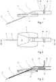
- FIG. 1 and FIG. 2 show an infusion needle according to the invention with a needle receiving body 1, which initially has a metal cannula 2 and a cylindrical receiving opening 3 connected to it.
- the metal cannula 2 is designed as a puncture inner cannula and is surrounded by a somewhat shorter, conically ending plastic cannula 4, which is close to it and connected to the receiving opening 3.
- FIG 3 shows the infusion needle according to the invention of Figure 1 in longitudinal section.
- the configuration of the receiving opening 3 clearly emerges from it.
- the infusion needle according to the invention is characterized in that the metal cannula 2 as a puncture cannula is formed and is surrounded by a somewhat shorter, conical ending and close to it and connected to the receiving opening 3 plastic cannula, that the needle receiving body 1 is designed angled in the transition region between the receiving opening 3 and the plastic cannula 4, and that the metal cannula 2 from which it surrounds Plastic cannula 4 and the needle holder body 1 is designed to be extractable.
- the angle is between 15 and 25 o . In the illustrated and preferred embodiment, an angle of 20 o is provided.
- transition region between the cylindrical receiving opening 3 and the plastic cannula 4 is conical. In this way, on the one hand, the insertion of the metal cannula 2 and the plastic cannula 4 is facilitated, and on the other hand, the metal cannula 2 is given sufficient space for the bend required by the bend.
- the needle holder body 1 has a widened area 5 in the region of the bend. As can be seen in particular from FIGS. 1 and 3, this widening 5 is provided on the underside of the needle receiving body 1 having the plastic cannula 4 with an elastic support, which is preferably provided as an endless foam strip 6 running along the edges of the widening 5.
- the figures also show that the metal cannula 2 has a receiving element 7 with a molded grip plate 8 at its end facing away from the cannula tip.
- the needle receiving body 1 in the area of the receiving opening 3 and the receiving element 7 of the metal cannula 2 have means which prevent the inserted metal cannula 2 from rotating axially.
- the needle receiving body 1 has lateral projections 9 and the receiving element 7 has a web 10 in the form of a ring segment.
- the metal cannula 2 is bevelled in the area of its tip at a flat angle in order to ensure easier penetration into the skin.
Landscapes
- Health & Medical Sciences (AREA)
- Life Sciences & Earth Sciences (AREA)
- Biophysics (AREA)
- Pulmonology (AREA)
- Engineering & Computer Science (AREA)
- Anesthesiology (AREA)
- Biomedical Technology (AREA)
- Heart & Thoracic Surgery (AREA)
- Hematology (AREA)
- Animal Behavior & Ethology (AREA)
- General Health & Medical Sciences (AREA)
- Public Health (AREA)
- Veterinary Medicine (AREA)
- Infusion, Injection, And Reservoir Apparatuses (AREA)
Abstract
Description
- Vorliegende Erfindung betrifft eine Infusionsnadel, insbesondere für die allgemeine Infusionstherapie, mit einem eine Metallkanüle und eine damit in Verbindung stehende zylinderförmige Aufnahmeöffnung zur Aufnahme von Applikatoren aufweisenden Nadelaufnahmekörper, wobei die Metallkanüle als Punktionskanüle ausgebildet ist und von einer etwas kürzeren, konisch endenden und dicht anliegenden sowie mit der Aufnahmeöffnung verbundenen Kunststoffkanüle umgeben ist.
- Neben der oralen und rektalen Applikation von Medikamenten ist die parenterale Verabreichung von Pharmaka eine der Grundlagen der heutigen Therapie. Auch wenn in der modernen Medizin die intravenöse Infusionstherapie und arterielle Injektionstechnik die Injektionstherapie der drei klassischen Injektionsformen, also die subkutane, die intramuskuläre und die intravenöse Applikation von Medikamenten teilweise verdrängt hat, stellt die subkutane und intrakutane Applikation - insbesondere im Bereich der Schmerztherapie und der Behandlung von Diabetes - nach wie vor einen großen Bereich der Infusionstherapie dar. Ihre Entwicklung verlief in vielen kleinen Schritten und über einen langen Zeitraum. Methoden zum Aderlaß und zu Zwecken der Zuführung von Medikamenten sind schon lange Zeit bekannt.
- Mit der Entdeckung des Blutkreislaufes zu Anfang des 17. Jahrhunderts war die anatomisch-physiologische Basis bezüglich der Infusion und Transfusion geschaffen worden. Schon bald begannen erste Infusionsversuche, erst bei Tieren und später auch am Menschen, die jedoch zunächst weder einen therapeutischen Effekt noch einen Fortschritt der Erkenntnis zu erzielen vermochten. Da der Grund für die anfänglichen Mißerfolge wohl in erster Linie auf die septischen Verhältnisse zurückzuführen war, ermöglichte erst die Erfindung der Injektionsspritze im 19. Jahrhundert den Weg zur modernen Injektions- und Infusionstherapie. Jedoch begann ein neues Kapitel in der Transfusionslehre erst nach der Blutgruppenentdeckung zu Anfang dieses Jahrhunderts. Erst damit konnten die entscheidenden Grundlagen und Techniken entwickelt werden, die - angeregt durch die beiden Weltkriege und die Entwicklung der inneren Medizin und der Anästhesiologie - größtenteils bis zum heutigen Tage noch Gültigkeit haben.
- Die subkutane Injektion stellt im Bereich der Schmerztherapie immer noch einen wichtigen Bereich dar, obwohl die Häufigkeit therapeutischer, subkutaner Injektionen im Gegensatz zu früher deutlich zurückgegangen ist. Dieser Rückgang liegt zum einen daran, daß die Resorptionszeiten schlecht bestimmbar sind und daß sie stark von dem Zustand des jeweiligen Patienten abhängen. Zum anderen werden heute mehr differente Mittel injiziert, die - subkutan appliziert - unverträglich sind. Doch spielt die subkutane Technik und insbesondere die subkutanen Infusionen bei Kindern nach wie vor eine wesentliche Rolle.
- Bei der subkutanen Infusion ist es sehr wichtig, daß die Injektionen lege artis durchgeführt werden, weil eine Injektion in die Kutis nicht nur starke Schmerzen verursacht, sondern zu heftigen Entzündungen bis hin zu Nekrosen der Haut führen kann. Ebenfalls bekannt sind die ödimatösen Quaddeln nach subkutaner Injektion, die mit mehr oder minder starker Entzündung einhergehen, so daß die Kranken of recht empfindlich in ihrem Wohlbefinden beeinträchtigt sind. Jedoch sind diese Komplikationen meist harmlos und verschwinden in wenigen Tagen. In seltenen Fällen können sie aber auch zur Nekrose der Haut und durch Sekundärinfektion zu einem Erysipel und bei ungünstiger Ausgangslage des Patienten zu einer Sepsis führen. Die intrakutane Injektion spielt auch heute noch bei der BCG-Schutzimpfung (Bacille-Calmette- Guerin; Schutzimpfung gegen Tuberkulose) eine große Rolle. Sie wird vielfach in der Heiltherapie angewendet.
- Bei der subkutanen Injektion bzw. Infusion muß das Medikament unter die Haut in das subkutane Fettgewebe gespritzt bzw. gegeben werden, während bei der intrakutanen Injektion ein Arzneimitteldepot direkt in der Haut (Kutis) zu liegen kommt. Die meisten subkutanen Injektionen werden im Bereich des Oberarms, des Oberschenkels oder der Brust verabreicht. Im Gegensatz zu den anderen Injektionsmethoden gibt es bei der subkutanen Injektionstechnik keinen wesentlichen Unterschied bei der Anwendung dieser Therapie zwischen Männern, Frauen, Kindern und Säuglingen.
- Wärend bei der Injektion die Injektionsnadel nach dem Setzen eines Arzneimitteldepots durch Herausziehen wieder aus dem subkutanen oder intrakutanen Gewebe entfernt wird, verbleibt eine Infusionsnadel über einen längeren Zeitraum - gegebenenfalls bis zu einigen Tagen - am Applikationsort. Es ist schnell ersichtlich, daß dies für den Patienten unangenehm ist und ihn in seiner Bewegungsfreiheit behindert. Unumgängliche Bewegungen können mehr oder minder starke Schmerzen verursachen.
- Aus der CH-PS 400 463 ist eine Kanüle für Infusionen, insbesondere für Dauertropfinfusionen mit einem eine Metallkanüle und eine damit in Verbindung stehende zylinderförmige Aufnahmeöffnung aufweisenden Nadelaufnahmekörper bekannt. Bei dieser bekannten Kanüle ist die Metallkanüle als Punktionskanüle ausgebildet und von einer etwas kürzeren, konisch endenden und dicht anliegenden sowie mit der Aufnahmeöffnung verbundenen Kunststoffkanüle umgeben. Diese bekannte Infusionsnadel weist eine Metallkanüle auf, welche in einem flachen Winkel zur Hautoberfläche im subkutanen oder intrakutanen Gewebe zu liegen kommt. Auch wenn die bekannte Infusionsnadel einfach auf der Haut zu befestigen ist, trägt sie jedoch - bedingt durch die Abwinklung - relativ hoch auf und hat demzufolge ein Scheuern z.B. auf der Kleidung des Patienten zur Folge, was wiederum mit Schmerzen für den Patienten verbunden sein kann.
- Der vorliegenden Erfindung liegt daher die Aufgabe zugrunde, die bekannte und zuvor näher beschriebene Infusionsnadel so auszugestalten und weiterzubilden, daß eine bestmögliche Anpassung an Bewegungen des Patienten erreicht wird, ohne auf den sicheren Halt der Infusionsnadel am Applikationsort verzichten zu müssen.
- Diese Aufgabe wird erfindungsgemäß dadurch gelöst, daß der Nadelaufnahmekörper im Übergangsbereich zwischen Aufnahmeöffnung und Kunststoffkanüle abgewinkelt ausgeführt ist, und daß die Metallkanüle aus der sie umschließenden Kunststoffkanüle und dem Nadelaufnahmekörper herausziehbar ausgebildet ist.
- Erfindungsgemäß wird eine Infusionsnadel geschaffen, bei der die Metallkanüle nur noch für die eigentliche Injektion benötigt wird. Nach der Injektion der Infusionsnadel und deren Befestigung am Applikationsort wird die Metallkanüle, der sogenannte Mandrin - wie bei einer Braunüle (eingetragenes Warenzeichen der Firma B. Braun Melsungen AG) - aus der sie umschließenden Kunststoffkanüle entfernt. Relative Bewegungen der Subkutis zur Epidermis sind für den Patienten nunmehr nahezu schmerzfrei, da sich die flexible Kunststoffkanüle solchen Relativbewegungen anpassen kann, ohne ihre Position im wesentlichen zu verändern. Bedingt durch die Abwinklung der erfindungsgemäßen Infusionsnadel wird erreicht, daß die Aufnahmeöffnung des Nadelaufnahme - körpers nahezu parallel zur Hautoberfläche verläuft. Diese Abwinklung sollte zwischen 15 und 25o betragen. Als besonders vorteilhaft hat sich ein Winkel von 20o erwiesen.
- Nach einer weiteren Lehre der Erfindung ist der Übergangsbereich zwischen der zylinderförmigen Aufnahmeöffnung und der Kunststoffkanüle konisch ausgebildet. Auf diese Weise wird erreicht, daß der Mandrin bei der Herstellung der Infusionsnadel beim Einführen in die Kunststoffkanüle diese nicht beschädigen kann und es wird darüber hinaus eine gleichmäßige Biegung des Mandrins im abgewinkelten Übergangsbereich zwischen Aufnahmeöffnung und Kunststoffkanüle ermöglicht.
- In weiterer Ausgestaltung der Erfindung weist der Nadelaufnahmekörper im Bereich der Abwinklung eine flächige Verbreiterung auf, welche auf der die Kunststoffkanüle aufweisenden Seite mit einer elastischen Auflage versehen ist. Als besonders zweckmäßig hat sich als elastische Auflage ein entlang den Rändern der Verbreiterung verlaufender endloser Schaumstoffstreifen erwiesen. Eine solche elastische Auflage ist für sich bereits von den sog. "Gripper"-Nadeln, wie sie bei voll implantierbaren Kathetersystemen eingesetzt werden, bekannt.
- Besonders zweckmäßig ist es, wenn die Metallkanüle an ihrem der Kanülenspitze abgewandten Ende ein Aufnahmeelement mit angeformter Griffplatte aufweist. Dadurch wird eine sichere Handhabung der erfindungsgemäßen Infusionsnadel beim Injizieren erreicht.
- Eine weitere Lehre der Erfindung sieht vor, daß der Nadelaufnahmekörper im Bereich der Aufnahmeöffnung und/oder das Aufnahmeelement der Metallhülse Mittel aufweist, welche ein axiales Verdrehen der eingeführten Metallkanüle verhindern. Auf diese Weise wird - je nach Punktionsart - die gewünschte feste Zuordnung der schräg angeschliffenen Metallkanülenspitze zum Nadelaufnahmekörper gewährleistet.
- Es gibt nun verschiedene Möglichkeiten, die Lehre der Erfindung auszugestalten und weiterzubilden, wozu einerseits auch die Unteransprüche und andererseits auch die nachfolgende Erläuterung eines bevorzugten Ausführungsbeispiels der erfindungsgemäßen Infusionsnadel anhand der Zeichnung verwiesen wird. In der Zeichnung zeigen
- Fig. 1
- eine Seitenansicht der erfindungsgemäßen Infusionsnadel,
- Fig. 2
- eine Draufsicht auf die erfindungsgemäße Injektionsnadel und
- Fig. 3
- einen Längsschnitt durch die erfindungsgemäße Injektionsnadel entlang der Linie III-III aus Figur 2.
- In Figur 1 und Figur 2 ist eine erfindungsgemäße Infusionsnadel mit einem Nadelaufnahmekörper 1 dargestellt, welcher zunächst eine Metallkanüle 2 und eine damit in Verbindung stehende zylinderförmige Aufnahmeöffnung 3 aufweist. Dabei ist die Metallkanüle 2 als Punktionsinnenkanüle ausgebildet und von einer etwas kürzeren, konisch endenden und dicht an ihr anliegenden sowie mit der Aufnahmeöffnung 3 verbundenen Kunststoffkanüle 4 umgeben.
- Figur 3 zeigt die erfindungsgemäße Infusionsnadel nach Figur 1 im Längsschnitt. Aus ihr geht deutlich die Ausgestaltung der Aufnahmeöffnung 3 hervor. Die erfindungsgemäße Infusionsnadel zeichnet sich dadurch aus, daß die Metallkanüle 2 als Punktionskanüle ausgebildet ist und von einer etwas kürzeren, konisch endenden und dicht an ihr anliegenden sowie mit der Aufnahmeöffnung 3 verbundenen Kunststoffkanüle umgeben ist, daß der Nadelaufnahmekörper 1 im Übergangsbereich zwischen Aufnahmeöffnung 3 und Kunststoffkanüle 4 abgewinkelt ausgeführt ist, und daß die Metallkanüle 2 aus der sie umschließenden Kunststoffkanüle 4 und dem Nadelaufnahmekörper 1 herausziehbar ausgebildet ist. Wie bereits erwähnt, ist es vorteilhaft, wenn die Abwinklung zwischen 15 und 25o beträgt. Im dargestellten und insoweit bevorzugten Ausführungsbeispiel ist ein Winkel von 20o vorgesehen.
- Aus Figur 3 ist ferner zu entnehmen, daß der Übergangsbereich zwischen der zylinderförmigen Aufnahmeöffnung 3 und der Kunststoffkanüle 4 konisch ausgebildet ist. Hierdurch wird zum einen das Einführen der Metallkanüle 2 und die Kunststoffkanüle 4 erleichtert und zum anderen erhält die Metallkanüle 2 einen ausreichenden Freiraum für ihre durch die Abwinklung erforderliche Biegung.
- Zur Befestigung der erfindungsgemäßen Infusionsnadel am Applikationsort weist der Nadelaufnahmekörper 1 im Bereich der Abwinklung eine flächige Verbreiterung 5 auf. Wie insbesondere aus den Figuren 1 und 3 hervorgeht, ist diese Verbreiterung 5 auf der die Kunststoffkanüle 4 aufweisenden Unterseite des Nadelaufnahmekörpers 1 mit einer elastischen Auflage versehen, welche vorzugsweise als ein entlang den Rändern der Verbreiterung 5 verlaufender endloser Schaumstoffstreifen 6 vorgesehen ist.
- Die Figuren zeigen ferner, daß die Metallkanüle 2 an ihrem der Kanülenspitze abgewandten Ende ein Aufnahmeelement 7 mit angeformter Griffplatte 8 aufweist.
- Auf diese Weise ist es möglich, auch durch die gesetzte Metallkanüle 2 bereits ein Medikament zu injizieren.
- Zur besseren Handhabung ist schließlich vorgesehen, daß der Nadelaufnahmekörper 1 im Bereich der Aufnahmeöffnung 3 und das Aufnahmeelement 7 der Metallkanüle 2 Mittel aufweisen, die ein axiales Verdrehen der eingeführten Metallkanüle 2 verhindern. Hierzu weist der Nadelaufnahmekörper 1, wie aus Figur 1 hervorgeht, seitliche Vorsprünge 9 und das Aufnahmeelement 7 einen ringsegmentartigen Steg 10 auf. Dies ist für eine sichere Handhabung unumgänglich, da die Metallkanüle 2 im Bereich ihrer Spitze unter einem flachen Winkel angeschrägt ausgeführt ist, um ein leichteres Eindringen in die Haut zu gewährleisten. Nach dem Setzen der erfindungsgemäßen Infusionsnadel ruht der Nadelaufnahmekörper 1 mit seiner mit der elastischen Auflage 6 versehenen Verbreiterung 5 auf der Oberfläche der Haut des Patienten. Nachdem dort eine entsprechende Fixierung stattgefunden hat, läßt sich der Mandrin 2 aus der Kunststoffkanüle 4 herausziehen und ein entsprechender Applikator kann mit Aufnahmeöffnung 3 des Nadelaufnahmekörpers 1 verbunden werden.
- Aus den Figuren geht deutlich hervor, daß nach herausgezogenem Mandrin 2 einschließlich Aufnahmeelement 7 und Griffplatte 8 der gesamte Nadelaufnahmekörper 1 nur noch sehr gering aufträgt, nämlich im wesentlichen nur noch um die Höhe der Außenabmessung des Nadelaufnahme körpers 1 im Bereich der Aufnahmeöffnung 3, da der Schaumstoffstreifen 6 durch seine Fixierung am Applikationsort noch zusammengedrückt wird.
-
- 1
- Nadelkörper
- 2
- Metallkanüle
- 3
- Aufnahmeöffnung
- 4
- Kunststoffkanüle
- 5
- Verbreiterung
- 6
- Schaumstoffstreifen
- 7
- Aufnahmeelement
- 8
- Griffplatte
- 9
- Vorsprung
- 10
- Steg
Claims (7)
- Infusionsnadel, insbesondere für die allgemeine Infusionstherapie, mit einem eine Metallkanüle und eine damit in Verbindung stehende zylinderförmige Aufnahmeöffnung aufweisenden Nadelaufnahmekörper, wobei die Metallkanüle als Punktionskanüle ausgebildet ist und von einer etwas kürzeren, konisch endenden und dicht anliegenden sowie mit der Aufnahmeöffnung verbundenen Kunststoffkanüle umgeben ist, dadurch gekennzeichnet, daß der Nadelaufnahmekörper (1) im Übergangsbereich zwischen Aufnahmeöffnung (3) und Kunststoffkanüle (4) abgewinkelt ausgeführt ist, und daß die Metallkanüle (2) aus der sie umschließenden Kunststoffkanüle (4) und dem Nadelaufnahmekörper (1) herausziehbar ausgebildet ist.
- Infusionsnadel nach Anspruch 1. dadurch gekennzeichnet, daß die Abwinklung zwischen 15 und 25o, vorzugsweise 20o beträgt.
- Infusionsnadel nach Anspruch 1 oder 2, dadurch gekennzeichnet, daß der Übergangsbereich zwischen der zylinderförmigen Aufnahmeöffnung (3) und der Kunststoffkanüle (4) konisch ausgebildet ist.
- Infusionsnadel nach einem der Ansprüche 1 bis 3, dadurch gekennzeichnet, daß der Nadelaufnahmekörper (1) im Bereich der Abwinklung eine flächige Verbreiterung (5) aufweist und daß die Verbreiterung (5) auf der die Kunststoffkanüle (4) aufweisenden Seite mit einer elastischen Auflage versehen ist.
- Infusionsnadel nach Anspruch 4, dadurch gekennzeichnet, daß als elastische Auflage ein entlang den Rändern der Verbreiterung (5) verlaufender endloser Schaumstoffstreifen (6) vorgesehen ist.
- Infusionsnadel nach einem der Ansprüche 1 bis 5, dadurch gekennzeichnet, daß die Metallkanüle (2) an ihrem der Kanülenspitze abgewandten Ende ein Aufnahmeelement (7) mit angeformter Griffplatte (8) aufweist.
- Infusionsnadel nach Anspruche 6, dadurch gekennzeichnet, daß der Nadelaufnahmekörper (1) im Bereich der Aufnahmeöffnung (3) und/oder das Aufnahmeelement (7) der Metallkanüle (2) Mittel (9,10) aufweisen bzw. aufweist, welche ein axiales Verdrehen der eingeführten Metallkanüle (2) verhindern.
Applications Claiming Priority (2)
| Application Number | Priority Date | Filing Date | Title |
|---|---|---|---|
| DE4211932A DE4211932C1 (de) | 1992-04-09 | 1992-04-09 | |
| DE4211932 | 1992-04-09 |
Publications (3)
| Publication Number | Publication Date |
|---|---|
| EP0564797A2 true EP0564797A2 (de) | 1993-10-13 |
| EP0564797A3 EP0564797A3 (de) | 1994-03-16 |
| EP0564797B1 EP0564797B1 (de) | 1998-09-02 |
Family
ID=6456464
Family Applications (1)
| Application Number | Title | Priority Date | Filing Date |
|---|---|---|---|
| EP93102936A Expired - Lifetime EP0564797B1 (de) | 1992-04-09 | 1993-02-25 | Infusionsnadel |
Country Status (7)
| Country | Link |
|---|---|
| US (1) | US5356389A (de) |
| EP (1) | EP0564797B1 (de) |
| JP (1) | JPH067441A (de) |
| AT (1) | ATE170405T1 (de) |
| CA (1) | CA2088700A1 (de) |
| DE (2) | DE4211932C1 (de) |
| ES (1) | ES2121882T3 (de) |
Cited By (1)
| Publication number | Priority date | Publication date | Assignee | Title |
|---|---|---|---|---|
| EP2133109A4 (de) * | 2007-03-30 | 2014-10-15 | Terumo Corp | Verweilnadelanordnung |
Families Citing this family (17)
| Publication number | Priority date | Publication date | Assignee | Title |
|---|---|---|---|---|
| FR2708858B1 (fr) * | 1993-08-09 | 1995-09-08 | Zambon France Sa | Dispositif de perfusion à ailettes de protection. |
| DE19546809A1 (de) * | 1995-12-14 | 1997-07-03 | Willing Erika | Venenverweilkanüle |
| US5919160A (en) * | 1996-10-10 | 1999-07-06 | Sanfilippo, Ii; Dominic Joseph | Vascular access device and method of installing same |
| US5906594A (en) | 1997-01-08 | 1999-05-25 | Symbiosis Corporation | Endoscopic infusion needle having dual distal stops |
| US6056718A (en) | 1998-03-04 | 2000-05-02 | Minimed Inc. | Medication infusion set |
| US6135984A (en) * | 1999-01-06 | 2000-10-24 | Dishler; Jon G. | Cannula for use in corrective laser eye surgery |
| DE10109742B4 (de) * | 2001-02-28 | 2005-12-22 | Tecpharma Licensing Ag | Kanülenträger mit flexibler Kanüle |
| DE10117286A1 (de) * | 2001-04-06 | 2002-10-17 | Disetronic Licensing Ag | Weiche Kanüle |
| US7153316B1 (en) | 2001-11-09 | 2006-12-26 | Mcdonald Marguerite B | Surgical instruments and method for corneal reformation |
| US7083598B2 (en) * | 2002-08-27 | 2006-08-01 | Jan Liska | Transcutan catheter assembly |
| US20070135769A1 (en) * | 2005-12-09 | 2007-06-14 | Tollini Dennis R | Device and method for supporting a medical device |
| DE102007049446A1 (de) | 2007-10-16 | 2009-04-23 | Cequr Aps | Katheter-Einführeinrichtung |
| CN102284100A (zh) * | 2011-06-24 | 2011-12-21 | 孔祥红 | 输液进针器 |
| US10080839B2 (en) * | 2013-03-14 | 2018-09-25 | Becton, Dickinson And Company | Angled inserter for drug infusion |
| US9427079B2 (en) * | 2014-02-28 | 2016-08-30 | Young Microbrush, Llc | Dental dispensing tip and method of manufacturing |
| USD785797S1 (en) | 2014-02-28 | 2017-05-02 | Young Microbrush, Llc | Dental dispensing tip |
| DE102016107131B4 (de) | 2016-04-18 | 2020-02-13 | Gerresheimer Regensburg Gmbh | Werkzeug zum Herstellen einer Injektionsvorrichtung und Verfahren zum Herstellen einer Injektionsvorrichtung |
Family Cites Families (15)
| Publication number | Priority date | Publication date | Assignee | Title |
|---|---|---|---|---|
| US2008340A (en) * | 1934-05-15 | 1935-07-16 | Salvati Alberto Tomas | Surgical injection needle and the like |
| US2402306A (en) * | 1943-10-07 | 1946-06-18 | Turkel Henry | Retaining guard guide for needles |
| NL281166A (de) * | 1961-07-29 | |||
| CH400436A (de) * | 1961-09-01 | 1965-10-15 | Regnas Adolf | Rotationsmaschine |
| FR2245383A1 (en) * | 1973-05-11 | 1975-04-25 | Inst Nat Sante Rech Med | Continuous sampling catheter equipment - has nozzle with main and lateral branches and nylon tube |
| US3900026A (en) * | 1973-11-19 | 1975-08-19 | William H Wagner | Device for holding and protecting intravenous injection needles |
| US4292970A (en) * | 1980-01-24 | 1981-10-06 | Hession Jr William M | Apparatus for intravenous catheter starter |
| US4392853A (en) * | 1981-03-16 | 1983-07-12 | Rudolph Muto | Sterile assembly for protecting and fastening an indwelling device |
| DE3327585A1 (de) * | 1982-08-06 | 1984-02-09 | John Martin Oxford Evans | Chirurgisches instrument fuer die epidurale und spinale anaesthesie |
| US4690675A (en) * | 1984-11-19 | 1987-09-01 | William Katz | Intravenous needle assembly |
| DE3539243A1 (de) * | 1985-11-05 | 1987-05-21 | Manfred Rycyk | Punktionskanuele |
| US4834708A (en) * | 1987-03-31 | 1989-05-30 | George Pillari | Puncture needle assembly |
| US4846805A (en) * | 1987-12-04 | 1989-07-11 | Icu Medical, Inc. | Catheter insert device |
| US5084033A (en) * | 1990-03-12 | 1992-01-28 | Minnesota Mining And Manufacturing Company | Arterial cannula tip and method of manufacture |
| US5163913A (en) * | 1990-04-25 | 1992-11-17 | Becton, Dickinson And Company | Apparatus and method for connecting a catheter and a winged inserter body in fluid tight relation |
-
1992
- 1992-04-09 DE DE4211932A patent/DE4211932C1/de not_active Expired - Fee Related
-
1993
- 1993-02-25 DE DE59308938T patent/DE59308938D1/de not_active Expired - Fee Related
- 1993-02-25 ES ES93102936T patent/ES2121882T3/es not_active Expired - Lifetime
- 1993-02-25 EP EP93102936A patent/EP0564797B1/de not_active Expired - Lifetime
- 1993-02-25 AT AT93102936T patent/ATE170405T1/de not_active IP Right Cessation
- 1993-03-30 CA CA002088700A patent/CA2088700A1/en not_active Abandoned
- 1993-04-05 US US08/042,807 patent/US5356389A/en not_active Expired - Fee Related
- 1993-04-05 JP JP5077957A patent/JPH067441A/ja active Pending
Cited By (1)
| Publication number | Priority date | Publication date | Assignee | Title |
|---|---|---|---|---|
| EP2133109A4 (de) * | 2007-03-30 | 2014-10-15 | Terumo Corp | Verweilnadelanordnung |
Also Published As
| Publication number | Publication date |
|---|---|
| DE4211932C1 (de) | 1993-04-29 |
| EP0564797B1 (de) | 1998-09-02 |
| CA2088700A1 (en) | 1993-10-10 |
| DE59308938D1 (de) | 1998-10-08 |
| JPH067441A (ja) | 1994-01-18 |
| ES2121882T3 (es) | 1998-12-16 |
| ATE170405T1 (de) | 1998-09-15 |
| US5356389A (en) | 1994-10-18 |
| EP0564797A3 (de) | 1994-03-16 |
Similar Documents
| Publication | Publication Date | Title |
|---|---|---|
| EP0564797B1 (de) | Infusionsnadel | |
| DE2238722C3 (de) | Katheter | |
| DE69123817T2 (de) | Gerät zum Abdichten von Punkturwunden | |
| DE69402343T2 (de) | Katheter- und Nadeleinrichtung zum Verabreichen therapeutischer Lösungen | |
| DE69215958T2 (de) | Untergetunneltes Epiduralkatheter | |
| DE69925022T2 (de) | Blutdichtung mit einem federbelasteten septum | |
| DE69835603T2 (de) | Führungsdrahtgeeignete Einspritzportanordnung | |
| DE102015117923A1 (de) | Punktionssystem | |
| DE3013384A1 (de) | Kanuele | |
| WO1981000210A1 (fr) | Dispositif pour seringues a injection | |
| DE2121699B2 (de) | Injektionsnadel aus Metall mit Kupplungsteil | |
| DE10113984A1 (de) | Vorrichtung und Verfahren zum Führen von Nadeln für subkutane Injektionsspritzen und Begrenzen ihres Zuganges zu einem Septum einer in einen Menschen implantierbaren Vorrichtung zur medizinischen Behandlung | |
| EP0102498B1 (de) | Katheterset | |
| DE1566588B1 (de) | Vorrichtung zum Einfuehren eines Katheters | |
| DE69318821T2 (de) | Katheter zur Versorgung des Penis mit Medikamenten | |
| DE69016997T2 (de) | Vorrichtung mit einer hohlen Nadel und einem Reservoir. | |
| WO1992018193A1 (de) | Venen-verweil-kanüle | |
| DE2240694A1 (de) | Spritze fuer intravenoese oder intramuskulaere injektion | |
| EP0261598B1 (de) | Injektionseinrichtung | |
| DE9204937U1 (de) | Infusionsnadel | |
| DE9413128U1 (de) | Infusionsnadel | |
| DE102010019614A1 (de) | Punktionsnadelabdeckung mit einem Mikronadelarray | |
| DE1809364A1 (de) | Organpunktionskatheter,vorzugsweise fuer medizinische Anwendungen | |
| DE3851543T2 (de) | Markkatheter. | |
| DE69318983T2 (de) | Vorrichtung zur verabreichung einer flüssigkeit |
Legal Events
| Date | Code | Title | Description |
|---|---|---|---|
| PUAI | Public reference made under article 153(3) epc to a published international application that has entered the european phase |
Free format text: ORIGINAL CODE: 0009012 |
|
| AK | Designated contracting states |
Kind code of ref document: A2 Designated state(s): AT CH DE ES FR GB IT LI NL SE |
|
| PUAL | Search report despatched |
Free format text: ORIGINAL CODE: 0009013 |
|
| AK | Designated contracting states |
Kind code of ref document: A3 Designated state(s): AT CH DE ES FR GB IT LI NL SE |
|
| 17P | Request for examination filed |
Effective date: 19940906 |
|
| 17Q | First examination report despatched |
Effective date: 19960404 |
|
| GRAG | Despatch of communication of intention to grant |
Free format text: ORIGINAL CODE: EPIDOS AGRA |
|
| GRAG | Despatch of communication of intention to grant |
Free format text: ORIGINAL CODE: EPIDOS AGRA |
|
| GRAH | Despatch of communication of intention to grant a patent |
Free format text: ORIGINAL CODE: EPIDOS IGRA |
|
| GRAH | Despatch of communication of intention to grant a patent |
Free format text: ORIGINAL CODE: EPIDOS IGRA |
|
| GRAH | Despatch of communication of intention to grant a patent |
Free format text: ORIGINAL CODE: EPIDOS IGRA |
|
| GRAH | Despatch of communication of intention to grant a patent |
Free format text: ORIGINAL CODE: EPIDOS IGRA |
|
| GRAA | (expected) grant |
Free format text: ORIGINAL CODE: 0009210 |
|
| AK | Designated contracting states |
Kind code of ref document: B1 Designated state(s): AT CH DE ES FR GB IT LI NL SE |
|
| REF | Corresponds to: |
Ref document number: 170405 Country of ref document: AT Date of ref document: 19980915 Kind code of ref document: T |
|
| REG | Reference to a national code |
Ref country code: CH Ref legal event code: NV Representative=s name: TROESCH SCHEIDEGGER WERNER AG Ref country code: CH Ref legal event code: EP |
|
| GBT | Gb: translation of ep patent filed (gb section 77(6)(a)/1977) |
Effective date: 19980903 |
|
| REF | Corresponds to: |
Ref document number: 59308938 Country of ref document: DE Date of ref document: 19981008 |
|
| REG | Reference to a national code |
Ref country code: ES Ref legal event code: FG2A Ref document number: 2121882 Country of ref document: ES Kind code of ref document: T3 |
|
| ET | Fr: translation filed | ||
| PG25 | Lapsed in a contracting state [announced via postgrant information from national office to epo] |
Ref country code: AT Free format text: LAPSE BECAUSE OF NON-PAYMENT OF DUE FEES Effective date: 19990225 |
|
| PG25 | Lapsed in a contracting state [announced via postgrant information from national office to epo] |
Ref country code: SE Free format text: LAPSE BECAUSE OF NON-PAYMENT OF DUE FEES Effective date: 19990226 Ref country code: ES Free format text: LAPSE BECAUSE OF NON-PAYMENT OF DUE FEES Effective date: 19990226 |
|
| PG25 | Lapsed in a contracting state [announced via postgrant information from national office to epo] |
Ref country code: LI Free format text: LAPSE BECAUSE OF NON-PAYMENT OF DUE FEES Effective date: 19990228 Ref country code: CH Free format text: LAPSE BECAUSE OF NON-PAYMENT OF DUE FEES Effective date: 19990228 |
|
| PLBE | No opposition filed within time limit |
Free format text: ORIGINAL CODE: 0009261 |
|
| STAA | Information on the status of an ep patent application or granted ep patent |
Free format text: STATUS: NO OPPOSITION FILED WITHIN TIME LIMIT |
|
| 26N | No opposition filed | ||
| PGFP | Annual fee paid to national office [announced via postgrant information from national office to epo] |
Ref country code: GB Payment date: 19990825 Year of fee payment: 7 |
|
| PG25 | Lapsed in a contracting state [announced via postgrant information from national office to epo] |
Ref country code: NL Free format text: LAPSE BECAUSE OF NON-PAYMENT OF DUE FEES Effective date: 19990901 |
|
| REG | Reference to a national code |
Ref country code: CH Ref legal event code: PL |
|
| PG25 | Lapsed in a contracting state [announced via postgrant information from national office to epo] |
Ref country code: FR Free format text: LAPSE BECAUSE OF NON-PAYMENT OF DUE FEES Effective date: 19991029 |
|
| EUG | Se: european patent has lapsed |
Ref document number: 93102936.7 |
|
| REG | Reference to a national code |
Ref country code: FR Ref legal event code: ST |
|
| PG25 | Lapsed in a contracting state [announced via postgrant information from national office to epo] |
Ref country code: GB Free format text: LAPSE BECAUSE OF NON-PAYMENT OF DUE FEES Effective date: 20000225 |
|
| GBPC | Gb: european patent ceased through non-payment of renewal fee |
Effective date: 20000225 |
|
| PGFP | Annual fee paid to national office [announced via postgrant information from national office to epo] |
Ref country code: DE Payment date: 20010327 Year of fee payment: 9 |
|
| PG25 | Lapsed in a contracting state [announced via postgrant information from national office to epo] |
Ref country code: DE Free format text: LAPSE BECAUSE OF NON-PAYMENT OF DUE FEES Effective date: 20020903 |
|
| REG | Reference to a national code |
Ref country code: ES Ref legal event code: FD2A Effective date: 20000310 |
|
| PG25 | Lapsed in a contracting state [announced via postgrant information from national office to epo] |
Ref country code: IT Free format text: LAPSE BECAUSE OF NON-PAYMENT OF DUE FEES;WARNING: LAPSES OF ITALIAN PATENTS WITH EFFECTIVE DATE BEFORE 2007 MAY HAVE OCCURRED AT ANY TIME BEFORE 2007. THE CORRECT EFFECTIVE DATE MAY BE DIFFERENT FROM THE ONE RECORDED. Effective date: 20050225 |