EP0564657B1 - Panneau de visualisation - Google Patents
Panneau de visualisation Download PDFInfo
- Publication number
- EP0564657B1 EP0564657B1 EP92921003A EP92921003A EP0564657B1 EP 0564657 B1 EP0564657 B1 EP 0564657B1 EP 92921003 A EP92921003 A EP 92921003A EP 92921003 A EP92921003 A EP 92921003A EP 0564657 B1 EP0564657 B1 EP 0564657B1
- Authority
- EP
- European Patent Office
- Prior art keywords
- sheet
- frame
- stretching
- swollen
- portions
- Prior art date
- Legal status (The legal status is an assumption and is not a legal conclusion. Google has not performed a legal analysis and makes no representation as to the accuracy of the status listed.)
- Expired - Lifetime
Links
Images


Classifications
-
- G—PHYSICS
- G09—EDUCATION; CRYPTOGRAPHY; DISPLAY; ADVERTISING; SEALS
- G09F—DISPLAYING; ADVERTISING; SIGNS; LABELS OR NAME-PLATES; SEALS
- G09F13/00—Illuminated signs; Luminous advertising
- G09F13/04—Signs, boards or panels, illuminated from behind the insignia
-
- G—PHYSICS
- G09—EDUCATION; CRYPTOGRAPHY; DISPLAY; ADVERTISING; SEALS
- G09F—DISPLAYING; ADVERTISING; SIGNS; LABELS OR NAME-PLATES; SEALS
- G09F9/00—Indicating arrangements for variable information in which the information is built-up on a support by selection or combination of individual elements
-
- G—PHYSICS
- G09—EDUCATION; CRYPTOGRAPHY; DISPLAY; ADVERTISING; SEALS
- G09F—DISPLAYING; ADVERTISING; SIGNS; LABELS OR NAME-PLATES; SEALS
- G09F13/00—Illuminated signs; Luminous advertising
- G09F13/04—Signs, boards or panels, illuminated from behind the insignia
- G09F13/0418—Constructional details
- G09F13/0454—Slidable panels or parts
-
- G—PHYSICS
- G09—EDUCATION; CRYPTOGRAPHY; DISPLAY; ADVERTISING; SEALS
- G09F—DISPLAYING; ADVERTISING; SIGNS; LABELS OR NAME-PLATES; SEALS
- G09F13/00—Illuminated signs; Luminous advertising
- G09F13/04—Signs, boards or panels, illuminated from behind the insignia
- G09F13/0418—Constructional details
- G09F13/0481—Signs, boards or panels having a curved shape
-
- G—PHYSICS
- G09—EDUCATION; CRYPTOGRAPHY; DISPLAY; ADVERTISING; SEALS
- G09F—DISPLAYING; ADVERTISING; SIGNS; LABELS OR NAME-PLATES; SEALS
- G09F15/00—Boards, hoardings, pillars, or like structures for notices, placards, posters, or the like
- G09F15/0006—Boards, hoardings, pillars, or like structures for notices, placards, posters, or the like planar structures comprising one or more panels
- G09F15/0025—Boards, hoardings, pillars, or like structures for notices, placards, posters, or the like planar structures comprising one or more panels display surface tensioning means
-
- G—PHYSICS
- G09—EDUCATION; CRYPTOGRAPHY; DISPLAY; ADVERTISING; SEALS
- G09F—DISPLAYING; ADVERTISING; SIGNS; LABELS OR NAME-PLATES; SEALS
- G09F13/00—Illuminated signs; Luminous advertising
- G09F13/04—Signs, boards or panels, illuminated from behind the insignia
- G09F13/0418—Constructional details
- G09F13/0472—Traffic signs
Definitions
- the present invention relates to a visual panel such as a lane decoration panel in a bowling alley, a display panel for outdoor wall and rooftop advertizement, and a display panel for advertizement in station precincts.
- a wall is used for a lifting device portion of an apparatus for automatically aligning and arranging bowling pins at a distal end of a lane so as to cover and conceal the lifting device portion from a competitor.
- the number of unknocked-down pins and the like are displayed on this wall by electric light.
- the display of the number of unknocked-down pins and the like has come to be given on a table or the like on the competitor's side.
- a multiplicity of panels on which pictures, photographs or the like are printed have come to be installed on the walls for covering and concealing the lifting device portion, so as to create a unique, favorable atmosphere of the interior of the bowling alley from the viewpoint of vision.
- EP-A-0,296,863 discloses a visual panel according to the preamble of claim 1 but in which the sheet tension may be adjusted to a limited extent by means of screws.
- JP-U-63-115171 discloses a visual panel also according to the preamble of claim 1 but which uses bottle screws for adjusting the tension of the sheet.
- a visual panel comprising:
- the frame and the stretching means may be formed of any of wood, metal, synthetic resin, and the like, but may preferably be formed of a hard plastic or aluminum, most preferably aluminum, in view of the mechanical strength or the light-weight characteristic.
- the tension adjusting means may be comprised of any of a ratchet-type lashing belt, a turnbuckle, a rubber band-type lashing belt, or a cam buckle-type lashing belt which are provided with hooks at both ends.
- the flexible sheet in the present invention may be a general sheet, such as a nylon sheet or a vinyl sheet obtained by extrusion molding, or a cloth or a nonwoven sheet formed of natural fibers or chemical fibers or a combination thereof.
- a back-lit type may preferably be used as the sheet.
- the swollen portion of the sheet it is possible to use one in which the edge portion of the sheet itself is made to swell by being integrally formed, or one which is obtained by tucking in the edge portion of the sheet itself.
- the swollen portion may be one in which the edge portion is turned up and sewn together, and a flexible rope is inserted into a loop formed therein.
- the cross-sectional configuration of this swollen portion may be a circular, triangular, quadrangular, or other polygonal shape.
- the flexible sheet may preferably be slightly stretchable, but if it is excessively stretchable, there are cases where the picture or the like formed by printing or the like is distorted.
- a picture, a photograph or the like is printed in advance on the flexible sheet.
- This sheet is stretched over the frame by using the stretching means, and is mounted in, for instance, a bowling alley or the like.
- the sheet is removed from the frame, and a sheet with a new different picture, a photograph or the like printed thereon is stretched over the frame.
- the new and old sheets are transported in a rolled-up state, the operation does not take up much space and is facilitated remarkably.
- the portion where a picture, a photograph or the like is printed is the flexible sheet and is arranged to be removable, replacement and transportation thereof are very easy. As a result, the operating efficiency is improved remarkably, and the replacement cost can be reduced.
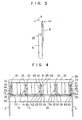
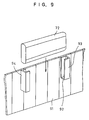
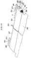
- each visual panel 1 is allotted to each of two lanes 3 in such a manner as to cover and conceal from a competitor a lifting device portion of an apparatus for automatically aligning and arranging bowling pins 4 at a distal end of the lane 3 in a bowling alley 2.
- the visual panels 1 are disposed in a series by being supported by columns 5 rotatably in the direction of A.
- Each visual panel 1 comprises a frame 6; a flexible sheet 11 having swollen portions 9 and 10 at opposite edge portions 7 and 8; sheet stretching means 12 for slidably accommodating the swollen portions 9 and 10 at the opposite edge portions 7 and 8; and tension adjusting means 13 for adjusting the tension applied to the sheet 11.
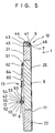
- the frame 6 has upper and lower horizontal members 21 and 22, left and right vertical members 23 and 24, and a plurality of intermediate vertical members 25, which are connected to each other by means of screws or the like.
- the frame 6 is disposed in such a manner as to be rotatable in the direction of A by means of hinge mechanisms comprised of shafts 26 and bearings (not shown) disposed in the left and right vertical members 23 and 24.
- the swollen portion 10 at the edge portion 8 of the sheet 11 is formed such that the edge portion 8 is turned up and sewn together, and a flexible rope 32 is inserted into a loop formed therein.
- the other swollen portion 9 is also formed in the same way as the swollen portion 10.
- the stretching means 12 has a first stretching device 41 for accommodating the swollen portion 9 at one edge portion 7 of the sheet 11 and a second stretching device 42 for accommodating the swollen portion 10 at the other edge portion 8 of the sheet 11.
- the stretching device 41 has a notch 43 formed in a front apex portion of the horizontal member 21 of the frame 6 and a cover plate 44 covering the notch 43 and secured to the horizontal member 21 by means of screws or the like.
- Formed in the stretching device 41 is a hole 45 for slidably accommodating the swollen portion 9 at the edge portion 7 of the sheet 11 by being surrounded by the curved cover plate 44 and the notch 43.
- the tip of the cover plate 44 is disposed with a slight gap between the same and the horizontal member 21 so as to form a slit 46 through which the edge portion 7 of the sheet 11 which continues to the swollen portion 9 is inserted.
- the first stretching device 41 secured to the frame 6 has the hole 45 for slidably accommodating the swollen portion 9 at the edge portion 7 of the sheet 11 and the slit 46 through which the edge portion 7 of the sheet 11 which continues to the swollen portion 9 is inserted.
- the stretching device 42 which is elongated has a cylindrical portion 52 having a slit 51 and a plate-like portion 54 formed integrally with the cylindrical portion 52 and having a plurality of rectangular through holes 53.
- the inner space of the cylindrical portion 52 is formed as a hole 55.
- the second stretching device 42 disposed movably with respect to the frame 6 has the hole 55 for slidably accommodating the swollen portion 10 at the edge portion 8 of the sheet 11 and the slit 51 through which the edge portion 8 of the sheet 11 which continues to the swollen portion 10 is inserted.
- the tension adjusting means 13 for adjusting the tension applied to the sheet 11 has the following: hook retainers 61 which are respectively secured to the vertical members 23 and 24 and the intermediate vertical members 25 by means of screws or the like; hooks 62 which are respectively retained at the hook retainers 61; other hooks 63 retained at the plate-like portion 54 through the through holes 53, respectively; lashing belts 64 each stretched between the hooks 62 and 63; and buckles 65 each attached to the lashing belt 64 so as to adjust the distance between the hooks 62 and 63.
- the tension adjusting means 13 is disposed between the stretching device 42 and the frame 6.
- the visual panel 1 formed as described above is disposed at the distal end of each lane 3 in the bowling alley 2, as shown in Fig. 1.
- a photograph printed on the front of the sheet 11 of the visual panel 1 the atmosphere of the interior of the bowling alley 2 is made a visually pleasing one.
- the visual panel 1 is rotated in the direction of A to cause the rear surface of the visual panel 1 to face the operator's side; the tension applied to the sheet 11 by means of the lashing belts 64 is alleviated; the swollen portions 9 and 10 are pulled out of the respective holes 45 and 55; the sheet 11 is removed from the frame 6; the swollen portion 10 of a new sheet 11 is inserted into the hole 55 in the horizontal direction, as shown in Fig. 6; and the other swollen portion 9 is similarly inserted into the hole 45 in the horizontal direction, thereby fitting the sheet 11 on the frame 6. Subsequently, one ends of the lashing belts 64 are pulled to impart an appropriate tensile force to the sheet 11, thereby stretching the sheet 11 tautly.
- the visual panels 1 make it possible to change the atmosphere of the interior of the bowling alley 2 simply by changing the sheets 11.
- the sheets 11 rendered unnecessary after being replaced and the new sheets 11 are flexible, they can be transported by being folded up or rolled up. Hence, the transportation of these sheets is not troublesome, and a multiplicity of sheets can be transported at one time, with the result that the operating efficiency is improved remarkably.
- the visual panel 1 is formed by the first stretching device 41 secured to the frame 6 and the second stretching device 42 disposed movably with respect to the frame 6.
- a first stretching device 71 for accommodating the swollen portion 9 at one edge portion 7 of the sheet 11 is formed in the same way as the stretching device 42, the hooks 62 are retained at the plate-like portion 54 of the stretching device 71 via the through holes 53 formed in the plate-like portion 54.
- the first and second stretching devices 71 and 42 are disposed movably with respect to the frame 6, and the tension adjusting means 13 is disposed between the first stretching device 71 and the second stretching device 42, thereby forming a visual panel 72.
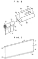
- the sheet 11 is stretched while being guided by space-forming members 73 and 74 attached to the upper and lower horizontal members 21 and 22 of the frame 6 by means of screws or the like, and a space 76 is formed between a front surface 75 of the frame 6 and the sheet 11 opposing the front surface 75 by means of the space-forming members 73 and 74.
- illuminating devices 77 such as fluorescent lamps may be provided, as required, and the sheet 11 may be illuminated from the rear by the illuminating devices 77, thereby obtaining a more favorable visual effect.
- covers 83 and 84 are respectively fitted at upper and lower ends of the frame 6 via mounting plates 81 and 82 secured to the frame 6 by means of screws or the like.
- a plurality of through holes 85 and 86 through which the lashing belts 64 can be inserted are formed in the mounting plates 81 and 82 in correspondence with the through holes 53.
- the visual panel of the present invention is not limited to such use.
- an arrangement may be provided such that U-shaped support members 93 and 94 each having a bottom plate 92 are fixed to an enclosing wall 91 provided in such a manner as to surround a construction site, and the visual panel 72 is inserted thereinto to give a display for the construction site.
- the illumination device 77 is mounted in the visual panel 72, a display can be provided favorably even at night. To change the contents of the display, it suffices if the sheet 11 is replaced as described above.
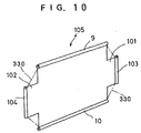
- a sheet 105 in which, in addition to the swollen portions 9 and 10, additional swollen portions 103 and 104 are respectively formed in horizontally projecting portions 101 and 102, as shown in Fig. 10.
- the frame 6 is enveloped by the sheet 105, and stretching devices and tension adjusting means are also used for the swollen portions 103 and 104 in the same way as described above. If this arrangement is adopted, a tensile force can be imparted to the sheet 105 in the horizontal direction as well, so that the sheet can be stretched more tightly in some cases.
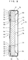
- a visual panel 201 of this embodiment comprises the flexible sheet 105 having the swollen portions 9 and 10, and 103 and 104 at the two sets of opposing edge portions; sheet stretching means 203 for slidably receiving the swollen portions 9 and 10 at the opposite edge portions of the sheet 105 and for stretching the sheet 105 over a frame 202; and tension adjusting means 204 for adjusting the tension applied to the sheet 105.
- the frame 202 of this embodiment includes a pair of vertical members 210 (one is not shown) disposed in parallel; horizontal members 211 and 212, and 213 and 214 whose ends are respectively secured to the pair of vertical members 210 by welding or other similar means and which are disposed in parallel with each other by bridging the pair of vertical members 210; and cylindrical members 215, 216 and 217 disposed in parallel with each other in the same way as these horizontal members 211, 212, 213 and 214.
- Intermediate vertical members are provided on the frame 202 in parallel with the vertical members 210, as required. Secured to respective one ends of the cylindrical members 215 and 216 are other ends of brackets 221 and 222 whose one ends are secured to the vertical members 210 by means of welding or the like.
- respective one ends of the cylindrical members 215 and 216 are supported by the vertical members 210 via the brackets 221 and 222.
- the other ends (not shown) of the cylindrical members 215 and 216 are also supported by brackets similar to the brackets 221 and 222.
- brackets similar to the brackets 221 and 222 may be provided between intermediate portions of the cylindrical members 215 and 216 on the one hand, and the horizontal members 213 and 214 or the intermediate vertical members on the other, so that the intermediate portions of the cylindrical members 215 and 216 will not be deflected.
- the cylindrical member 217 bridges and secures the pair of vertical members 210 in the same way as the horizontal members 211 and 212.
- a cover 231 is secured to the pair of vertical members 210 and the horizontal members 211 and 212 by means of fitting, screws or the like in such a manner as to cover the outer sides of these members.
- a first stretching device 241 for accommodating the swollen portion 9 at one edge portion of the sheet 105 and a second stretching device 242 for accommodating the swollen portion 10 at the other edge portion of the sheet 105 are each provided with couplers 251 and 252 and a plurality of adjusters 253 and 254.
- the coupler 251 is formed as being identical to the coupler 252, and the adjuster 253 is formed as being identical to the adjuster 254. Accordingly, a description will be given hereafter of only the coupler 251 and the adjuster 253.
- the elongated coupler 251 has a hole 261 for accommodating the swollen portion 9 at one edge portion of the sheet 105; a slit 262 through which the edge portion of the sheet 105 continuing to the swollen portion 9 is inserted; a hole 264 for slidably accommodating a swollen portion 263 of the adjuster 253; and a slit 266 through which a plate-like portion 265 of the adjuster 253 continuing to the swollen portion 263 is inserted.
- the holes 261 and 264 and the slits 262 and 266 are provided over the entire length of a body 267 of the coupler 251.
- Each of the adjusters 253 is provided with the swollen portion 263 and the plate-like portion 265 formed integrally with the swollen portion 263, as described above.
- a hollow portion 271 and a slit 272 communicating with the hollow portion 271 are formed in the swollen portion 263, and an elongated hole 273 is formed in the plate-like portion 265.
- a portion between its one end 281 and the hook portion 283 may be formed by a coil spring.
- a belt 291 of the tension adjusting means 204 is inserted through an elongated hole (not shown) in the plate-like portion of the adjuster 254 which is formed in the same way as the adjuster 253.
- the tension adjusting means 204 has the belt 291 and a buckle 292 connected to the belt 291.
- the belt 291 is inserted through the elongated hole (not shown) in the plate-like portion of the adjuster 254, as described above, and is trained to the cylindrical member 217.
- the distance between the adjuster 254 and the cylindrical member 217 can be shortened, thereby making it possible to stretch the sheet 105 tautly.
- the visual panel 201 of this embodiment is further provided with an edge cover 301 attached to the cover 231 rotatably in the direction of R via hinges 300 and a rear plate 302 having its peripheral edges fitted to the cover 231.
- the edge cover 301 can be secured to the cover 231 by means of screws 303, so that if the screws 303 are removed, the edge cover 301 is rotatable about the hinge 300 in the direction of R.
- a pad 305 is fitted to inner peripheral edges of the edge cover 301. The pad 305 clamps the sheet 105 in cooperation with the cylindrical members 215 and 216 and stretches slight creases and the like occurring in the sheet 105 to prevent them from occurring.
- Holding members 306 and 307 are attached to the vertical members 210 by means of welding or the like so as to hold the edge cover 301 securely when the edge cover 301 is closed.
- a multiplicity of fluorescent lamps 310 which are illuminating means, may be attached to the frame 202 via supports 311.
- mounting devices 321 and 322 may be attached to the vertical members 210 and the like by means of welding or the like.
- the mounting devices 321 and 322 are each constituted by a member 323 welded to the vertical member 210 or the like and a bracket 325 secured to the member 323 by means of bolts 324.
- the visual panel 201 formed as described above is mounted onto, for instance, an enclosure frame or the like at a construction site via horizontal pipes or horizontal bars 326 welded onto the brackets 325.
- the edge cover 301 is rotated in the direction of R after removing the screws 303, and if the belts 291 are then loosened to slacken the sheet 105, and the swollen portions 9 and 10 are drawn out from the couplers 251 and 252, the replacement of the sheet 105 can be performed easily.
- the sheet is provided only on one side of the frame, the sheet may be provided on both sides of the frame, in which case the illuminating devices may also be provided between the frame and the respective sheets.
- the visual panels may be arranged in the shape of a prism, e.g., a quadrangular prism, and castors may be provided at the lower ends of the visual panels so as to render the visual panels movable.
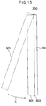
- this horizontally projecting portion may be formed in such a manner as to project with smooth arcuate edges 330.
Landscapes
- Physics & Mathematics (AREA)
- General Physics & Mathematics (AREA)
- Engineering & Computer Science (AREA)
- Theoretical Computer Science (AREA)
- Illuminated Signs And Luminous Advertising (AREA)
- Displays For Variable Information Using Movable Means (AREA)
Abstract
Claims (3)
- Panneau de visualisation qui comprend :- un cadre (202),- une feuille souple (105) comportant respectivement des premières parties renflées (9, 10) en ses parties marginales opposées, et- un moyen (203) d'étirage de feuille destiné à recevoir de manière coulissante lesdites parties renflées (9, 10) situées en lesdites parties marginales opposées de ladite feuille (105) et à étirer ladite feuille sur ledit cadre (202), et- un moyen (204) de réglage de la tension, servant à régler la tension appliquée à ladite feuille (202),ledit moyen d'étirage comprenant des premier et deuxième dispositifs d'étirage (241, 242) avec des premier et deuxième dispositifs d'accouplement respectifs (251, 252), allongés, comportant respectivement des premier et deuxième trous (261) destinés chacun à recevoir l'une desdites premières parties renflées (9, 10), et des première et deuxième fentes (262) par lesquelles une partie marginale de ladite feuille peut passer, ledit deuxième dispositif d'étirage (242) étant disposé de manière mobile par rapport audit cadre,
caractérisé en ce que :- ledit premier moyen d'étirage (241) comprend en outre une pluralité de premiers dispositifs de réglage (253) et ledit deuxième moyen d'étirage (242) comprend en outre une pluralité de deuxièmes dispositifs de réglage (254), chaque dispositif de réglage comprenant une deuxième partie renflée (263) qui fait corps avec une partie en forme de plaque (265) comportant un troisième trou oblong (273), lesdits premier et deuxième dispositifs d'accouplement comportant chacun un quatrième trou oblong (264) destiné à recevoir de manière coulissante les deuxièmes parties renflées des dispositifs de réglage respectifs et une troisième fente par laquelle peuvent passer les parties en forme de plaques (265), ledit premier moyen d'étirage étant fixé audit cadre (202) par un raccord de fixation (282) accroché dans lesdits troisièmes trous desdits premiers dispositifs de réglage (253), et- ledit moyen (204) de réglage de la tension comprend une courroie réglable (291) qui se met en prise avec ledit cadre (202) et lesdits troisièmes trous desdits deuxièmes dispositifs de réglage. - Panneau de visualisation selon la revendication 1, dans lequel ledit raccord de fixation (282) comprend un ressort à boudin.
- Panneau de visualisation selon la revendication 1 ou 2, dans lequel un dispositif d'éclairage est placé entre ladite feuille (105) et ledit cadre (202).
Applications Claiming Priority (3)
| Application Number | Priority Date | Filing Date | Title |
|---|---|---|---|
| JP306627/91 | 1991-10-25 | ||
| JP30662791 | 1991-10-25 | ||
| PCT/JP1992/001269 WO1993008554A1 (fr) | 1991-10-25 | 1992-10-01 | Panneau de visualisation |
Publications (3)
| Publication Number | Publication Date |
|---|---|
| EP0564657A4 EP0564657A4 (fr) | 1993-07-22 |
| EP0564657A1 EP0564657A1 (fr) | 1993-10-13 |
| EP0564657B1 true EP0564657B1 (fr) | 1997-03-26 |
Family
ID=17959367
Family Applications (1)
| Application Number | Title | Priority Date | Filing Date |
|---|---|---|---|
| EP92921003A Expired - Lifetime EP0564657B1 (fr) | 1991-10-25 | 1992-10-01 | Panneau de visualisation |
Country Status (8)
| Country | Link |
|---|---|
| US (1) | US5398436A (fr) |
| EP (1) | EP0564657B1 (fr) |
| KR (1) | KR960010771B1 (fr) |
| AU (1) | AU656232B2 (fr) |
| CA (1) | CA2098851C (fr) |
| DE (1) | DE69218585T2 (fr) |
| TW (1) | TW266284B (fr) |
| WO (1) | WO1993008554A1 (fr) |
Families Citing this family (28)
| Publication number | Priority date | Publication date | Assignee | Title |
|---|---|---|---|---|
| US5588236A (en) * | 1991-10-25 | 1996-12-31 | Scs Promotion Company Limited | Visual panel |
| DE9420817U1 (de) * | 1994-12-28 | 1995-03-30 | Dipl.-Ing. Rainer Kunze Heiligenstädter Kunststoffverarbeitung, 37318 Lutter | Vorrichtung zur Aufnahme eines flächenförmigen Werbeträgers |
| DE19519563A1 (de) * | 1995-05-27 | 1996-11-28 | Thoca Geraetebau Gmbh | Haltevorrichtung für Plakate |
| FR2739962B1 (fr) * | 1995-10-16 | 1997-11-28 | J P N Fixations Sa | Dispositif d'affichage |
| FR2743923B1 (fr) * | 1996-01-23 | 1998-02-20 | Ipam | Dispositif de fixation d'une banderole sur un mat |
| US6112444A (en) * | 1996-06-27 | 2000-09-05 | Milliken; Les | Framing member for use in assembling a bleed sign face construction |
| US5732494A (en) * | 1996-08-12 | 1998-03-31 | Davey; Glenn | Banner material holder |
| US5903993A (en) * | 1997-02-14 | 1999-05-18 | Nomadic Structures, Inc. | Connectors, display frame apparatus and method of use |
| GR1002993B (el) * | 1997-07-07 | 1998-10-14 | Panel 2+4 �.�. | Υπαιθρια φωτεινη διαφημιστικη πινακιδα ταχειας αλλαγης διαφημιστικων μηνυματων |
| US6092319A (en) * | 1998-04-13 | 2000-07-25 | Hicks; Charles H. | Apparatus for connecting advertising substrate to trucks |
| US6282822B1 (en) | 1999-03-30 | 2001-09-04 | Aegis Mobile Marketing | Mobile advertising display for roll-up door |
| US6402110B1 (en) * | 1999-09-29 | 2002-06-11 | Joel Berman Associates, Inc. | Apparatus and method for mounting flexible sheet material to a support structure |
| US6367204B1 (en) * | 2000-02-14 | 2002-04-09 | Donald Lewis Eichler | Method and apparatus for decorating doors |
| US20020011015A1 (en) * | 2000-05-04 | 2002-01-31 | Reed Larson | Banner caps and system of use |
| US6594932B2 (en) | 2001-02-22 | 2003-07-22 | Rak Tek, Inc. | Display sign mounting system |
| US6823619B2 (en) | 2001-05-03 | 2004-11-30 | Wizard Co., Inc. | Method and apparatus for suspending a plurality of signs |
| US6976330B2 (en) * | 2002-04-04 | 2005-12-20 | Milliken & Milliken | Hinge assembly for sign box face |
| US20050279465A1 (en) * | 2004-06-18 | 2005-12-22 | Ted Gower | Structure envelope reinforcement |
| US7500325B2 (en) * | 2004-11-15 | 2009-03-10 | Michael Wayne Pulliam | Apparatus and method for retaining and selectively tensioning a sheet material display to a billboard |
| US7481013B2 (en) * | 2005-02-24 | 2009-01-27 | Black John L | Billboard system and method |
| US7275340B2 (en) * | 2005-08-18 | 2007-10-02 | Boyd Andrews | Four-sided flexible display truck-side retention system |
| JP5422035B2 (ja) * | 2007-09-07 | 2014-02-19 | モリト株式会社 | 取付部品と取付対象物との連結方法 |
| GB2457505B (en) | 2008-02-18 | 2013-03-20 | Cestrian Imaging Ltd | Method of assembling a tensile fabric arrangement |
| US8997824B2 (en) * | 2011-03-16 | 2015-04-07 | Brent Walker | Solar shutter |
| USD735073S1 (en) * | 2013-10-01 | 2015-07-28 | Mydor, LLC | Door banner |
| US9422732B2 (en) | 2014-04-28 | 2016-08-23 | Ted Gower | Slidable barriers |
| US9512612B2 (en) | 2014-12-05 | 2016-12-06 | Ted Gower | Retainer inserts for barriers |
| DE102016216381A1 (de) * | 2016-08-31 | 2018-03-01 | Robert Bosch Gmbh | Display-Einheit, Display-Vorrichtung enthaltend mindestens eine Display-Einheit und Verwendung der Display-Einheit und der Display-Vorrichtung |
Family Cites Families (49)
| Publication number | Priority date | Publication date | Assignee | Title |
|---|---|---|---|---|
| US2338297A (en) * | 1938-10-19 | 1944-01-04 | Mugdan Martin | Process for polymerizing trichlorethylene |
| US2391871A (en) * | 1945-01-23 | 1946-01-01 | Albert H Benson | Window or the like for canvas coverings |
| US2527258A (en) * | 1948-10-15 | 1950-10-24 | Kalan Uniform Co Inc | Garment |
| US2647261A (en) * | 1950-05-13 | 1953-08-04 | Sidney Bogad | Sport shirt having detachable insignia panel |
| US2928198A (en) * | 1957-07-29 | 1960-03-15 | Madanick Sydney | Illuminated sign |
| US3276512A (en) * | 1963-12-16 | 1966-10-04 | Donald G Gallagher | Cover for the interior of an automobile |
| US3461584A (en) * | 1967-02-17 | 1969-08-19 | Wilson Seat Co | Sign holder for application to vehicle doors |
| AU3622168A (en) * | 1968-08-30 | 1970-03-05 | Hurricane Canvas Pty Ltd | An improved clip for releasably holding flexible sheet material |
| US3701210A (en) * | 1970-06-09 | 1972-10-31 | George E Smith | Temporary vehicle markings |
| DE2217826A1 (de) * | 1972-04-13 | 1973-10-25 | Kusto Gmbh | Vorrichtung mit einer plane zur befestigung an baugeruesten fuer den winterbau |
| US3831304A (en) * | 1972-08-24 | 1974-08-27 | Massillon Cleveland Akron Sign Co | Pole banner sign construction |
| DE2336733A1 (de) * | 1973-07-19 | 1975-02-06 | Schall Kg M | Zelt |
| DE2363706A1 (de) * | 1973-12-21 | 1975-06-26 | Huels Chemische Werke Ag | System zur bekleidung von allgemein gekruemmten flaechen |
| DE2407552A1 (de) * | 1974-02-16 | 1975-08-28 | Layher Gmbh Wilhelm | Anordnung zum verbinden von planen |
| JPS5142783A (en) * | 1974-10-09 | 1976-04-12 | Sanyo Kokusaku Pulp Co | Supuritsutoyaaniri kosasekisoshiitoseizohoho |
| US3995715A (en) * | 1975-09-10 | 1976-12-07 | A. Ahlstrom Osakeyhtio | Protective covering for scaffolding |
| US4018260A (en) * | 1976-04-27 | 1977-04-19 | Baslow Floyd M | Fabric wall coverings |
| IT1084259B (it) * | 1977-04-21 | 1985-05-25 | Hillebrand Peter | Copertura apribile e smontabile per ambienti di grandi dimensioni |
| US4107826A (en) * | 1978-01-23 | 1978-08-22 | Tysdal Daryl D | Flexible covering anchor |
| JPS5529454A (en) * | 1978-08-16 | 1980-03-01 | Nippon Dekishi Kk | Method of and apparatus for wrapping and charging article |
| JPS5766936A (en) * | 1980-10-15 | 1982-04-23 | Teijin Ltd | Polyester film |
| US4369591A (en) * | 1981-06-03 | 1983-01-25 | Vicino Robert K | Inflatable display structure |
| AU8848582A (en) * | 1981-09-25 | 1983-03-31 | Spring, A.D. Mfg. Pty. Ltd. | Clamps and methods for connecting flexible sheet to tubular frames |
| DE3142829A1 (de) * | 1981-10-29 | 1983-05-11 | Dambach-Templin Gmbh & Co Werbemittel Kg, 7560 Gaggenau | Wechselplakat |
| EP0078391A1 (fr) * | 1981-10-28 | 1983-05-11 | Dambach-Templin GmbH & Co. Werbemittel KG | Disposition d'affiches publicitaires sur les bâches des camions |
| US4534145A (en) * | 1983-07-25 | 1985-08-13 | The Firestone Tire & Rubber Company | Attachment device for securing flexible sheets |
| US4532744A (en) * | 1983-09-06 | 1985-08-06 | The Firestone Tire & Rubber Company | Locking device for membrane fastener apparatus |
| DE3412064A1 (de) * | 1984-03-31 | 1985-10-03 | Sascha 6000 Frankfurt Weingärtner | Werbetraegerschild fuer kraftfahrzeuge |
| US4572691A (en) * | 1984-07-02 | 1986-02-25 | Minnesota Mining And Manufacturing Company | Pen-like instrument for applying correction fluid |
| FR2572832B1 (fr) * | 1984-11-07 | 1987-01-23 | Rhone Poulenc Fibres | Moyen permettant la publicite escamotable, et son procede de mise en oeuvre |
| US4746597A (en) * | 1986-10-22 | 1988-05-24 | Minnesota Mining And Manufacturing Co. | Image deletion fluid for printing plate |
| JPS63115171U (fr) * | 1987-01-22 | 1988-07-25 | ||
| FR2610374B1 (fr) * | 1987-01-30 | 1989-05-12 | Dalo Jean | Dispositif de fixation du bord d'une nappe tendue, applicable notamment a la fixation du bord inferieur d'une toile de tente et abri leger pourvu d'un tel dispositif |
| US4757854B1 (en) * | 1987-02-26 | 1998-06-23 | Bestop Inc | Apparatus for detachably fastening a stretchable fabric panel to a rigid frame |
| US4776121A (en) * | 1987-04-27 | 1988-10-11 | Vicino Robert K | Inflatable sign |
| FR2616050B1 (fr) * | 1987-06-05 | 1989-12-29 | Bassouls Pierre Henry | Dispositif de solidarisation temporaire des extremites de deux structures dont au moins une est souple |
| US5042182A (en) * | 1987-06-25 | 1991-08-27 | Signcraft Pty. Limited | Sign |
| JPS6438672A (en) * | 1987-08-05 | 1989-02-08 | Hitachi Ltd | Pattern generator |
| US4800947A (en) * | 1987-09-21 | 1989-01-31 | Joseph K. Favata | Tension mounting system and assembly |
| FR2624062B1 (fr) * | 1987-12-08 | 1991-04-12 | Chenel Guy | Cloison temporaire |
| CA1311122C (fr) * | 1988-02-09 | 1992-12-08 | Paul G. Sheppard | Systeme d'affichage illumine |
| JPH01229109A (ja) * | 1988-03-03 | 1989-09-12 | Color 2000 Inc | シート材料を吊下げるための吊下げアセンブリ |
| US4875302A (en) * | 1988-04-07 | 1989-10-24 | Noffsinger Alfred A | Collapsible display sign |
| US4976057A (en) * | 1988-07-21 | 1990-12-11 | Bianchi Dennis R | Simulated neon sign |
| US4878303A (en) * | 1988-07-25 | 1989-11-07 | Banniza Harry W | Sign |
| JPH0287283A (ja) * | 1988-09-22 | 1990-03-28 | Nec Ic Microcomput Syst Ltd | 半導体集積回路装置 |
| GB2226591A (en) * | 1988-12-21 | 1990-07-04 | Sgb Plc | Protective screen for use during building operations |
| JPH02190890A (ja) * | 1988-12-26 | 1990-07-26 | Signcraft Pty Ltd | 看板 |
| GB8903932D0 (en) * | 1989-02-21 | 1989-04-05 | Urquhart Peter J | Fastening flexible sheets |
-
1992
- 1992-10-01 CA CA002098851A patent/CA2098851C/fr not_active Expired - Fee Related
- 1992-10-01 US US07/039,070 patent/US5398436A/en not_active Expired - Fee Related
- 1992-10-01 DE DE69218585T patent/DE69218585T2/de not_active Expired - Fee Related
- 1992-10-01 WO PCT/JP1992/001269 patent/WO1993008554A1/fr active IP Right Grant
- 1992-10-01 KR KR1019930701281A patent/KR960010771B1/ko not_active IP Right Cessation
- 1992-10-01 AU AU26743/92A patent/AU656232B2/en not_active Ceased
- 1992-10-01 EP EP92921003A patent/EP0564657B1/fr not_active Expired - Lifetime
- 1992-10-15 TW TW081108198A patent/TW266284B/zh active
Also Published As
| Publication number | Publication date |
|---|---|
| EP0564657A4 (fr) | 1993-07-22 |
| CA2098851A1 (fr) | 1993-04-26 |
| WO1993008554A1 (fr) | 1993-04-29 |
| KR960010771B1 (ko) | 1996-08-08 |
| DE69218585D1 (de) | 1997-04-30 |
| AU656232B2 (en) | 1995-01-27 |
| EP0564657A1 (fr) | 1993-10-13 |
| KR930702737A (ko) | 1993-09-09 |
| AU2674392A (en) | 1993-05-21 |
| US5398436A (en) | 1995-03-21 |
| TW266284B (fr) | 1995-12-21 |
| DE69218585T2 (de) | 1997-07-10 |
| CA2098851C (fr) | 1998-06-16 |
Similar Documents
| Publication | Publication Date | Title |
|---|---|---|
| EP0564657B1 (fr) | Panneau de visualisation | |
| US4800947A (en) | Tension mounting system and assembly | |
| US5046545A (en) | Tension mounting system and assembly | |
| EP0382478B1 (fr) | Dispositif d'affichage | |
| US5588236A (en) | Visual panel | |
| CA1311122C (fr) | Systeme d'affichage illumine | |
| US4922988A (en) | Tension mounting system and assembly | |
| CA1177647A (fr) | Panneau publicitaire pour camionnettes et vehicules analogues | |
| US4052805A (en) | Card and bulletin displayer mounting on wall or door | |
| ES2085838T3 (es) | Dispositivo de presentacion individual y selectiva de un conjunto de carteles. | |
| US20060078320A1 (en) | Variable background for photographic pictures | |
| US4089361A (en) | Reel apparatus for background sheet | |
| EP0119762B1 (fr) | Tension de feuilles flexibles sur des cadres | |
| US20010047602A1 (en) | Frame apparatus and method for stretching flexible material | |
| US5436804A (en) | Light-modifying screen for use in photography | |
| JP2707835B2 (ja) | ビジュアルパネル | |
| EP0519161B1 (fr) | Encadrement d'assemblage modulaire pour signes illuminées utilisant du matériel flexible | |
| EP0570562B2 (fr) | Panneau publicitaire | |
| JP2526485B2 (ja) | ビジュアルパネル | |
| CA2156033A1 (fr) | Structure de tension pour auvent | |
| EP0801371A1 (fr) | Dispositif d'affichage publicitaire | |
| US20240257669A1 (en) | Framing system for fabric signs | |
| HUT69850A (en) | Knock-down elements framework for flexible light signs | |
| WO1995034059A1 (fr) | Agencement destine a la fixation d'un materiau en feuille sur une surface | |
| JPH0720790A (ja) | 立て看板 |
Legal Events
| Date | Code | Title | Description |
|---|---|---|---|
| PUAI | Public reference made under article 153(3) epc to a published international application that has entered the european phase |
Free format text: ORIGINAL CODE: 0009012 |
|
| 17P | Request for examination filed |
Effective date: 19930521 |
|
| AK | Designated contracting states |
Kind code of ref document: A1 Designated state(s): DE FR GB |
|
| 17Q | First examination report despatched |
Effective date: 19950609 |
|
| GRAG | Despatch of communication of intention to grant |
Free format text: ORIGINAL CODE: EPIDOS AGRA |
|
| GRAH | Despatch of communication of intention to grant a patent |
Free format text: ORIGINAL CODE: EPIDOS IGRA |
|
| GRAH | Despatch of communication of intention to grant a patent |
Free format text: ORIGINAL CODE: EPIDOS IGRA |
|
| GRAA | (expected) grant |
Free format text: ORIGINAL CODE: 0009210 |
|
| AK | Designated contracting states |
Kind code of ref document: B1 Designated state(s): DE FR GB |
|
| ET | Fr: translation filed | ||
| RAP4 | Party data changed (patent owner data changed or rights of a patent transferred) |
Owner name: SCS PROMOTION COMPANY LIMITED |
|
| REF | Corresponds to: |
Ref document number: 69218585 Country of ref document: DE Date of ref document: 19970430 |
|
| PLBE | No opposition filed within time limit |
Free format text: ORIGINAL CODE: 0009261 |
|
| STAA | Information on the status of an ep patent application or granted ep patent |
Free format text: STATUS: NO OPPOSITION FILED WITHIN TIME LIMIT |
|
| 26N | No opposition filed | ||
| PGFP | Annual fee paid to national office [announced via postgrant information from national office to epo] |
Ref country code: GB Payment date: 20000927 Year of fee payment: 9 |
|
| PGFP | Annual fee paid to national office [announced via postgrant information from national office to epo] |
Ref country code: FR Payment date: 20001004 Year of fee payment: 9 |
|
| PGFP | Annual fee paid to national office [announced via postgrant information from national office to epo] |
Ref country code: DE Payment date: 20001229 Year of fee payment: 9 |
|
| PG25 | Lapsed in a contracting state [announced via postgrant information from national office to epo] |
Ref country code: GB Free format text: LAPSE BECAUSE OF NON-PAYMENT OF DUE FEES Effective date: 20011001 |
|
| REG | Reference to a national code |
Ref country code: GB Ref legal event code: IF02 |
|
| GBPC | Gb: european patent ceased through non-payment of renewal fee |
Effective date: 20011001 |
|
| PG25 | Lapsed in a contracting state [announced via postgrant information from national office to epo] |
Ref country code: FR Free format text: LAPSE BECAUSE OF NON-PAYMENT OF DUE FEES Effective date: 20020628 |
|
| PG25 | Lapsed in a contracting state [announced via postgrant information from national office to epo] |
Ref country code: DE Free format text: LAPSE BECAUSE OF NON-PAYMENT OF DUE FEES Effective date: 20020702 |
|
| REG | Reference to a national code |
Ref country code: FR Ref legal event code: ST |