EP0564291B1 - Sheet transport path switching device for an image forming apparatus - Google Patents
Sheet transport path switching device for an image forming apparatus Download PDFInfo
- Publication number
- EP0564291B1 EP0564291B1 EP93302589A EP93302589A EP0564291B1 EP 0564291 B1 EP0564291 B1 EP 0564291B1 EP 93302589 A EP93302589 A EP 93302589A EP 93302589 A EP93302589 A EP 93302589A EP 0564291 B1 EP0564291 B1 EP 0564291B1
- Authority
- EP
- European Patent Office
- Prior art keywords
- sheet
- switch
- roller
- belt
- path
- Prior art date
- Legal status (The legal status is an assumption and is not a legal conclusion. Google has not performed a legal analysis and makes no representation as to the accuracy of the status listed.)
- Expired - Lifetime
Links
- 230000032258 transport Effects 0.000 claims description 106
- 230000002441 reversible effect Effects 0.000 claims description 18
- 230000008859 change Effects 0.000 claims description 2
- 238000000034 method Methods 0.000 description 10
- 230000002093 peripheral effect Effects 0.000 description 10
- 238000007639 printing Methods 0.000 description 8
- 230000009471 action Effects 0.000 description 3
- 230000008569 process Effects 0.000 description 3
- 230000004044 response Effects 0.000 description 3
- 238000010009 beating Methods 0.000 description 2
- 238000005452 bending Methods 0.000 description 2
- 230000015572 biosynthetic process Effects 0.000 description 2
- 229920001821 foam rubber Polymers 0.000 description 2
- 230000001737 promoting effect Effects 0.000 description 2
- 230000005540 biological transmission Effects 0.000 description 1
- 238000004140 cleaning Methods 0.000 description 1
- 239000000470 constituent Substances 0.000 description 1
- 238000010276 construction Methods 0.000 description 1
- 238000001816 cooling Methods 0.000 description 1
- 230000000593 degrading effect Effects 0.000 description 1
- 230000002708 enhancing effect Effects 0.000 description 1
- 238000003384 imaging method Methods 0.000 description 1
- 230000007246 mechanism Effects 0.000 description 1
- 230000003287 optical effect Effects 0.000 description 1
- 230000000717 retained effect Effects 0.000 description 1
- 238000000926 separation method Methods 0.000 description 1
Images


Classifications
-
- B—PERFORMING OPERATIONS; TRANSPORTING
- B65—CONVEYING; PACKING; STORING; HANDLING THIN OR FILAMENTARY MATERIAL
- B65H—HANDLING THIN OR FILAMENTARY MATERIAL, e.g. SHEETS, WEBS, CABLES
- B65H29/00—Delivering or advancing articles from machines; Advancing articles to or into piles
- B65H29/58—Article switches or diverters
-
- B—PERFORMING OPERATIONS; TRANSPORTING
- B65—CONVEYING; PACKING; STORING; HANDLING THIN OR FILAMENTARY MATERIAL
- B65H—HANDLING THIN OR FILAMENTARY MATERIAL, e.g. SHEETS, WEBS, CABLES
- B65H2301/00—Handling processes for sheets or webs
- B65H2301/40—Type of handling process
- B65H2301/44—Moving, forwarding, guiding material
- B65H2301/448—Diverting
- B65H2301/4482—Diverting to multiple paths, i.e. more than 2
- B65H2301/44822—3 paths
-
- B—PERFORMING OPERATIONS; TRANSPORTING
- B65—CONVEYING; PACKING; STORING; HANDLING THIN OR FILAMENTARY MATERIAL
- B65H—HANDLING THIN OR FILAMENTARY MATERIAL, e.g. SHEETS, WEBS, CABLES
- B65H2404/00—Parts for transporting or guiding the handled material
- B65H2404/10—Rollers
- B65H2404/11—Details of cross-section or profile
- B65H2404/115—Details of cross-section or profile other
- B65H2404/1151—Details of cross-section or profile other brush
-
- B—PERFORMING OPERATIONS; TRANSPORTING
- B65—CONVEYING; PACKING; STORING; HANDLING THIN OR FILAMENTARY MATERIAL
- B65H—HANDLING THIN OR FILAMENTARY MATERIAL, e.g. SHEETS, WEBS, CABLES
- B65H2404/00—Parts for transporting or guiding the handled material
- B65H2404/10—Rollers
- B65H2404/14—Roller pairs
- B65H2404/142—Roller pairs arranged on movable frame
- B65H2404/1421—Roller pairs arranged on movable frame rotating, pivoting or oscillating around an axis, e.g. parallel to the roller axis
-
- B—PERFORMING OPERATIONS; TRANSPORTING
- B65—CONVEYING; PACKING; STORING; HANDLING THIN OR FILAMENTARY MATERIAL
- B65H—HANDLING THIN OR FILAMENTARY MATERIAL, e.g. SHEETS, WEBS, CABLES
- B65H2404/00—Parts for transporting or guiding the handled material
- B65H2404/50—Surface of the elements in contact with the forwarded or guided material
- B65H2404/56—Flexible surface
- B65H2404/561—Bristles, brushes
-
- B—PERFORMING OPERATIONS; TRANSPORTING
- B65—CONVEYING; PACKING; STORING; HANDLING THIN OR FILAMENTARY MATERIAL
- B65H—HANDLING THIN OR FILAMENTARY MATERIAL, e.g. SHEETS, WEBS, CABLES
- B65H2404/00—Parts for transporting or guiding the handled material
- B65H2404/60—Other elements in face contact with handled material
- B65H2404/61—Longitudinally-extending strips, tubes, plates, or wires
- B65H2404/611—Longitudinally-extending strips, tubes, plates, or wires arranged to form a channel
- B65H2404/6112—Longitudinally-extending strips, tubes, plates, or wires arranged to form a channel and displaceable for changing direction of transport
-
- B—PERFORMING OPERATIONS; TRANSPORTING
- B65—CONVEYING; PACKING; STORING; HANDLING THIN OR FILAMENTARY MATERIAL
- B65H—HANDLING THIN OR FILAMENTARY MATERIAL, e.g. SHEETS, WEBS, CABLES
- B65H2404/00—Parts for transporting or guiding the handled material
- B65H2404/60—Other elements in face contact with handled material
- B65H2404/63—Oscillating, pivoting around an axis parallel to face of material, e.g. diverting means
-
- B—PERFORMING OPERATIONS; TRANSPORTING
- B65—CONVEYING; PACKING; STORING; HANDLING THIN OR FILAMENTARY MATERIAL
- B65H—HANDLING THIN OR FILAMENTARY MATERIAL, e.g. SHEETS, WEBS, CABLES
- B65H2513/00—Dynamic entities; Timing aspects
- B65H2513/10—Speed
Definitions
- the present invention relates to a device incorporated in a printer, copier, facsimile apparatus or similar image forming apparatus for switching the path for transporting sheets.
- a current trend in the imaging art is toward two-sided or duplex printing which forms an image on both sides of a sheet and, therefore, saves limited resources.
- Duplex printing is not practicable unless a sheet carrying an image on one side thereof is turned over and then refed to an image forming station.
- An image forming apparatus therefore, has to be provided with a sheet transport path switching device on a sheet transport route thereof. Even in the event of simplex printing which forms an image on only one side of a sheet, the switching device is indispensable in, for example, sorting the resulting one-sided sheets.
- Modern office automation equipment including printers and copiers have sorting, stacking and other advanced functions. While such advanced functions complicate the sheet transport route, there is an increasing demand for reducing the interval between consecutive sheets to produce a greater number of printings without changing the process speed.
- the conventional switching device implemented with the pawls cannot switch over the path at a speed high enough to meet the above demand since the switching speed is determined by the response of the pawls. Further, even when fast path switchover is not necessary, the pawls generally exert a load on a sheet and, therefore, often damages it or causes it to jam the path. On the other hand, the switching device using a suction system implements high speed path switchover. However, the suction system makes the switching device bulky and expensive and, in addition, produces noise.
- EP-A-407 151 discloses a transport device which uses a roller as a switching device. The disclosed arrangement only feeds two paths.
- an object of the present invention to provide a sheet transport path switching device for an image forming apparatus which surely steers sheets to any desired paths even when the sheets are continuously fed at an extremely short interval for high speed image formation.
- a sheet transport path switching device for an image forming apparatus comprising:
- a sheet transport path switching device for selectively steering a sheet being transported along a transport path to any one of a plurality of transport paths, said device comprising:
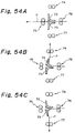
- the switching device has a pair of rotatable pawls 72 and 73.
- the pawls 72 and 73 assume a position shown in FIG. 54A, they steer a sheet P being driven by a transport roller pair 76 as indicated by an arrow straight to a path where a transport roller pair 75 is located.
- the pawl 72 is shifted to a position shown in FIG. 54B a solenoid or similar drive means, the sheet P is steered to a path where a transport roller pair 74 is located.
- the pawl 74 is shifted to a position shown in FIG. 54C, the sheet P is steered to a path where a transport roller pair 77 is located.
- the switching device relying on the pawls 72 and 73 cannot switch over the path at a high speed since the switching rate is determined by the response of the pawls 72 and 73. Further, even when fast path switchover is not necessary, the pawls 72 and 73 generally exert a load on the sheet P and, therefore, often damages it or causes it to jam the path, as discussed earlier.
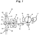
- FIG. 1 of the drawings a sheet transport path switching device embodying the present invention is shown together with a section which forms an image on a sheet.
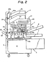
- a laser printer implemented with the embodiment is shown in FIG. 2.
- the laser printer has a printer body 1, a table 5 accommodating a two-side print or duplex unit 2 and a sheet feed unit 3 therein, and a sheet discharge unit 4 mounted on the top of the body 1.
- a photoconductive drum 8 is disposed in the printer body 1 and, as an image forming process begins, rotated in a direction indicated by an arrow in the figure by a motor, not shown.
- a main charger 9 uniformly charges the surface of the drum 8 being rotated.
- An optical writing unit 10 emits a laser beam having been modulated by image data. The laser beam scans the charged surface of the drum 8 in the axial direction of the drum 8, i.e., the main scanning direction, thereby electrostatically forming a latent image thereon.
- a developing unit 11 deposits a toner on the latent image to produce a corresponding toner image.
- An upper and a lower sheet tray 6 and 7 are mounted on the printer body 1 and provided with pick-up rollers 15a and 15b, respectively.
- the sheet feed unit 3 is provided with a pick-up roller 15c.
- a sheet, not shown, is fed from any one of the sheet trays 6 and 7 and sheet feed unit 3 by the associated pick-up roller 15a, 15b or 15.
- the sheet is once brought to a stop on abutting against a register roller pair 16 which adjoins the drum 8.
- the register roller pair 16 starts rotating in synchronism with the movement of the toner image formed on the drum 8 which is in rotation. As a result, the sheet is driven toward a position where the drum 8 and an image transfer an sheet separation unit 17 disposed below the drum 8 face each other.
- the unit 17 transfers the toner image from the drum 8 to the sheet by a transfer charger and separates the sheet carrying the toner image from the drum 8.
- a transport belt 18 conveys the sheet with the toner image to a fixing unit 19.
- the fixing unit 19 fixes the toner image on the sheet by heat.
- the sheet coming out of the fixing unit 19 is selectively steered toward an openable stacker 22 provided on the rear of the printer body 1, the sheet discharge unit 4 or the duplex unit 2, depending on the direction of rotation of a switch roller 21 included in a sheet transport path switching device 20 which will be described.
- a transport roller pair 23 is disposed in the printer body 1 while transport roller pairs 24 is disposed in the sheet discharge unit 4.
- the sheet discharge unit 4 includes a lower and an upper tray 4a and 4b. Discharge roller pairs 25a and 25b each discharges the sheet to the associated tray 4a or 4b.
- a register sensor RS is located just in front of the register roller pair 16 to sense the sheet.
- a cleaning unit 14 removes the toner remaining on the drum 8 after the image transfer. Further, a discharge lamp 26 dissipates the charge also remaining on the drum 8 after the image transfer. As a result, the drum 8 is initialized to prepare for the next image forming process.
- control boards 27 for controlling the entire printer and processing print data
- an engine driver 28 for controlling a printer engine constituting the image forming section
- the sheet transport path switching device 20 has an inlet roller pair 31 for transporting a sheet P in addition to the previously mentioned switch roller 21.
- the switch roller 21 is a reversible roller and located on a line L extending through the nip portion Np of the inlet roller pair 31 in the direction of sheet transport. As the direction in which the switch roller 21 rotates is changed, either of a path 33 terminating at the sheet discharge unit 4 and a path 34 terminating at the duplex unit 2 is selected.
- the switch roller 21 is reversibly driven by a motor, not shown, independent of the main motor for driving the various portions of the image forming system.
- a transport roller pair 35 is provided on the path 34 for transporting the sheet P and corresponds to the transport roller pair 23.
- Guide plates 36, 37 and 38 each guides the sheet P along the associated path 33 or 34.
- a sensor 12 is positioned at the inlet of the fixing unit 19.
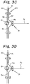
- FIGS. 3A-3D and 4A-4D A reference will be made to FIGS. 3A-3D and 4A-4D for describing the operation of the switching device 20. Assume that the device 20 steers sheets coming in one after another to the paths 33 and 34 alternately by way of example. In the figures, arrows indicate the directions in which the associated rollers rotate.
- FIG. 3A shows a condition wherein the inlet roller pair 31 has driven the first sheet P1 to a position where the leading edge of the sheet P1 slightly protrudes from the roller pair 31 on a line extending through the nip portion of the roller pair 31 in the direction of sheet feed (see the line L).
- the switch roller 21 is rotating counterclockwise to steer the sheet P1 toward the path 33.
- FIG. 3B as the leading edge Pa of the sheet P1 abuts against the switch roller 21, it is directed toward the path 33 by the rotation of the switch roller 21.
- FIG. 3C the sheet P1 is nipped and driven by the roller pair 23 to move the path 33 upward along the guide plates 36 and 37.
- the roller 21 is caused to rotate clockwise, as shown in FIG. 3D.
- the second sheet P2 arrives at the switch roller 21 immediately after the first sheet P1.
- the roller 21 steers it into the path 34. Consequently, the sheet P2 moves the path 34 downward along the guide plates 36 and 38 by being nipped by the roller pair 35.
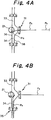
- the roller 21 is again rotated counterclockwise. Subsequently, as the leading edge of the third sheet P3 abuts against the switch roller 21, it is steered in the direction in which the roller 21 is rotating, as shown in FIG. 4D. Repeating such an operating, the device 20 can steer sheets to the paths 33 and 34 alternately with high efficiency, despite that the sheets are continuously fed into the device 20.
- the sheet P having been guided by the switch roller 21 in the event when the sheet P having been guided by the switch roller 21 is nipped and driven by the roller pair 23 or 35, the sheet P does not contact the roller 21 except for a small area adjoining the leading edge thereof.
- the sheet P having been guided by the switch roller 21 is spaced apart from the roller 21 when nipped and driven by the roller pair 23 or 35.
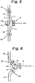
- the switch roller 21 and the roller pairs 23, 31 and 35 are positioned such that the periphery 21a of the roller 21 does not overlap a line L1 connecting the nip portions of the roller pairs 31 and 23 or a line L2 connecting the nip portions of the roller pairs 31 and 35.
- FIG. 6 shows a roller arrangement which does not satisfy the above-stated condition.
- the intermediate portion Pc of the sheet P contacts the periphery 21a of the switch roller 21.
- the switch roller 21 when the switch roller 21 is rotating in a direction different from the transport direction of the sheet P, it rubs itself against the side of the sheet P facing the roller 21 and thereby degrades an image which may exist there.
- the embodiment prevents the switch roller 21 from contacting the intermediate portion Pc of the sheet P, as stated above.
- the above-mentioned line L1 is a line tangential to the periphery of the upper roller of the roller pair 31 and the periphery of the right roller of the roller pair 23 on the switch roller 21 side, as viewed in FIG. 5.
- the line L2 is a line tangential to the lower roller of the roller pair 31 and the right roller of the roller pair 35 on the switch roller 21 side, as viewed in FIG. 5.
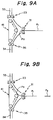
- FIGS. 7A-7D, 8A and 8B an alternative embodiment of the present invention will be described which changes the direction of rotation of the switch roller 21 before the trailing edge Pb of the sheet P1 is spaced apart from the roller 21.
- the operation of this embodiment will also be described on the assumption that sheets P sequentially coming in the switching device are steered to the paths 33 and 34 alternately.
- FIG. 7A shows a condition wherein the inlet roller pair 31 has driven the first sheet P1 to a position where the leading edge of the sheet P1 slightly protrudes from the nip portion of the roller pair 31.
- the switch roller 21 is rotating counterclockwise to steer the sheet P1 toward the path 33.
- FIG. 7B as the leading edge Pa of the sheet P1 abuts against the switch roller 21, it is directed toward the path 33 by the rotation of the switch roller 21.
- the sheet P1 is nipped and driven by the roller pair 23 to begin to move the path 33 upward along the guide plates 36 and 37.
- the switch roller 21 is reversed to rotate clockwise to prepare for the second sheet P2.
- the roller 21 steers it into the path 34, as shown in FIG. 7D.
- this embodiment changes, while a sheet is passing the switch roller 21, the rotating direction of the switch roller 21 to steer the next sheet. This insures efficient and exact switchover of the sheet transport path even when the interval between consecutive sheets is reduced substantially to zero.
- FIGS. 9A-9D and 10A-10D show another alternative embodiment of the present invention which uses an endless reversible belt 41 in place of the switch roller 21.
- the belt or switch belt 41 is located on a line extending through the nip portion of the roller pair 31 in the direction of sheet feed.
- the embodiment changes the direction for transporting the sheet P by changing the rotating direction of the switch belt 41. The operation will be described on the assumption that sheets sequentially coming in the switching device are steered to the paths 33 and 34 alternately.
- FIG. 9A shows a condition wherein the inlet roller pair 31 has driven the first sheet P1 to a position where the leading edge of the sheet P1 slightly protrudes from the nip portion of the roller pair 31.
- the switch belt 41 is rotating counterclockwise to steer the sheet P1 toward the path 33.
- FIG. 9B as the leading edge Pa of the sheet P1 abuts against the switch belt 41, it is directed toward the path 33 by the rotation of the switch belt 41.
- FIG. 9C the sheet P1 is nipped and driven by the roller pair 23 to move the path 33 upward along the guide plates 36 and 37.
- the belt 41 is caused to rotate clockwise, as shown in FIG. 9D.
- the belt 41 is, therefore, prepared to receive the second sheet P2 which will arrive in a short interval.
- the switch belt 41 enhances the free layout of the switching device for implementing various kinds of transport paths, compared to the switch roller 21.
- the switch belt 41 will be advantageous over the switch roller 21 when a longer distance is desired between the transport roller located at the inlet of the switching device and the transport roller located downstream of such a roller pair.
- this embodiment like the embodiment of FIGS. 5 and 6, locates the switch belt 41 such that the surface 41a of the belt 41 does not overlap a line L3 connecting the nip portions of the roller pairs 31 and 23 or a line connecting the nip portions of the roller pairs 31 and 35. This is also successful in preventing the switch belt 41 from rubbing itself against the intermediate portion of the sheet P.
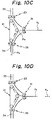
- FIGS. 12A-12D, 13A and 13B an alternative embodiment of the present invention will be described which changes the direction of rotation of the switch belt 41 before the trailing edge Pb of the sheet P1 is brought out of contact with the belt 41.
- the operation of this embodiment will also be described on the assumption that sheets P sequentially coming in the switching device are steered to the paths 33 and 34 alternately.
- the switch belt 41 has already started rotating counterclockwise.
- FIG. 12B as the leading edge Pa of the sheet P1 abuts against the switch belt 41, it is directed toward the path 33 by the rotation of the switch belt 41.
- FIG. 12C the sheet P1 is nipped and driven by the roller pair 23 to begin to move the path 33 upward along the guide plates 36 and 37.
- the switch belt 41 is reversed to rotate clockwise to prepare for the second sheet P2.
- the belt 41 steers the sheet P2 into the path 34, as shown in FIG. 12D.
- this embodiment changes, while a sheet is passing the switch belt 41, the direction of rotation of the belt 41 to steer the next sheet. This insures efficient and exact switchover of the sheet transport path even when the interval between consecutive sheets is reduced substantially to zero.
- FIGS. 14A-14D and 15A- 15D show another alternative embodiment of the present invention.
- a first and a second driven roller 43 and 44 are held in contact with the switch roller 21, and each is rotatable in one of opposite directions for transporting the sheet P.
- the switch roller 21, therefore, exerts a transporting force on the sheet P while steering it.
- the operation of this embodiment will be described on the assumption that sheets P sequentially coming in the switching device are steered to the paths 33 and 34 alternately.
- the nip portion of the switch roller 21 and driven roller 43 cooperate to convey a sheet toward the path 33, it cooperates with the nip portion of the inlet roller pair 31 to move the sheet P1 upward on the path 33 along the guide plates 36 and 37, as shown in FIG. 14C. Subsequently, as shown in FIG. 14D, when the trailing edge Pb of the sheet P1 leaves the nip portion of the switch roller 21 and driven roller 43, the roller 21 is reversed to rotate clockwise to prepare for the second sheet P2. At the same time, the driven rollers 43 and 44 are reversed by the switch roller 21.
- the roller 21 steers it toward the nip portion of the roller 21 and driven roller 44. Since the nip portion of the rollers 21 and 44 also cooperate to convey a sheet toward the path 34, the sheet P2 is moved downward on the path 34 along the guide plates 36 and 38, as shown in FIG. 15B. As shown in FIG. 15C, as soon as the trailing edge Pb of the sheet P2 leaves the nip portion of the rollers 21 and 44, the roller 21 is reversed to rotate counterclockwise while causing the driven rollers 43 and 44 to rotate clockwise. Thereafter, as shown in FIG. 15D, when the leading edge of the third sheet P3 abuts against the switch roller 21, the roller 21 steers it toward the nip portion of the roller 21 and driven roller 43 which is associated with the path 33.
- the switching device steers consecutive sheets to the paths 33 and 34 alternately.
- the driven rollers 43 and 44 each cooperates with the switch roller 21 to convey the sheet P having been directed toward the associated path. Hence, it is needless to locate transport roller pairs downstream of and in close proximity to the switch roller 21. As a result, the number of required parts is reduced to implement a compact design.
- FIGS. 16A-16D and 17A-17D show another alternative embodiment of the present invention which is essentially similar to the embodiment of FIGS. 14A-14D except that the switch roller 21 is replaced with the switch belt 41. The operation will be described on the assumption that sheets sequentially coming in the switching device are steered to the paths 33 and 34 alternately.
- the nip portion of the switch belt 41 and driven roller 43 function to convey a sheet toward the the path 33, it cooperates with the nip portion of the inlet roller pair 31 to move the sheet P1 upward along the path 33, as shown in FIG. 16C.
- the belt 41 is reversed to rotate clockwise and awaits the second sheet P2.
- the driven rollers 43 and 44 are rotated counterclockwise by the switch belt 41.
- the belt 41 steers it toward the nip portion of the belt 41 and driven roller 44. Since the nip portion of the switch belt 41 and driven roller 44 also functions to convey a sheet toward the path 34, the sheet P2 is transported on the path 34 along the guide plates 36 and 38, as shown in FIG. 17B. Subsequently, as shown in FIG. 17C, as the trailing edge Pb of the sheet P2 leaves the nip portion of the switch belt 41 and driven roller 44, the belt 41 is reversed to rotate counterclockwise and awaits the third sheet P3. At the same time, the driven rollers 43 and 44 are rotated clockwise by the switch belt 41. As shown in FIG. 17D, when the trailing edge Pa of the third sheet P3 abuts against the switch belt 41, the belt 41 steers it toward the nip portion of the belt 41 and driven roller 43 which is associated with the path 33.
- the switching device steers consecutive sheets to the paths 33 and 34 alternately.
- the switch roller 21 it is preferable to rotate the switch roller 21 at a peripheral speed equal to or higher than the transport speed of the inlet roller pair 31.
- the peripheral speed (transport speed) of the inlet roller pair 31 is V1
- the peripheral speed of the switch roller 21 is V2
- the speed V2 is lower than the speed V1.
- V2 is equal to or higher than V1
- the switch belt 41 be rotated at a peripheral speed V3 equal to or higher than the transport speed V1 of the roller pair 31.
- FIG. 20 shows a specific configuration of the switch roller 21.
- the periphery 21a of the switch roller 21 is knurled to form a number of grooves 21b in a direction perpendicular to the direction of rotation of the roller 21.
- the switch belt 41 may also be knurled to form a number of grooves 41b in a direction perpendicular to the direction of rotation of the belt 41.
- the grooves 21b or 41b will allow the roller 21 or the belt 41 to steer sheets more accurately.
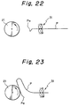
- FIGS. 22 and 23 are indicative of a drawback particular to the switch roller 21 lacking the grooves 21b.
- FIG. 22 assume that the leading edge Pa of the sheet P coming out of the inlet roller pair 31 has been bent. Then, when the leading edge Pa of the sheet P abuts against the switch roller 21, the roller 21 is apt to fail to retain the edge Pa and, therefore, to steer it in the rotating direction thereof (upward in this case), as shown in FIG. 23. In such a condition, it is likely that sheets P sequentially arriving at the switching device jam the path preceding the switch roller 21.
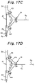
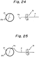
- the switch roller 21 with the grooves 21b is capable of surely retaining and steering the leading edge Pa of the sheet P which has been bent as shown in FIG. 24. This prevents sheets from jamming the path preceding the switch roller 21. This is also true with the switch belt 41 having the grooves 41b.
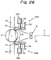
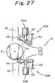
- the driven rollers 43 and 44 are pressed against the switch roller 21 and selectively moved out of contact with the roller 21 by retracting means 50A and 50B, respectively.
- the driven roller 43 or 44 is brought out of contact with the switch roller 21 by the retracting means 50A or 50B when the leading edge Pa of the sheet P has moved away from the roller 43 or 44.
- the retracting means 50A has a lever 51 supporting the driven roller 43 at one end in a rotatable manner, a spring 52 constantly biasing the lever 51 upward as viewed in FIG. 26, a pin 53 about which the lever 51 is rotatable, and a solenoid 54A for rotating the lever 51 against the action of the spring 52.
- the solenoid 54A When the solenoid 54A is not energized, the lever 51 is biased by the spring 52 to a position where the driven roller 43 is pressed against the switch roller 21 by a predetermined pressure.
- FIG. 27 when the solenoid 54A is energized, the lever 51 is rotated against the action of the spring 52 to move the driven roller 43 away from the switch roller 21.
- the retracting means 50B is identical in construction with the retracting means 50A.
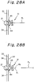
- the first sheet P1 is continuously transported on the path 33 along the guide plates 36 and 37 due to the force of the inlet roller pair 31.
- FIG. 28C when the leading edge of the second sheet P2 abuts against the switch roller 21, it is steered in the rotating direction of the switch roller 21, i.e., toward the nip portion of the roller 21 and driven roller 44.
- FIG. 28D when the leading edge of the sheet P2 moves away from the nip portion of the rollers 21 and 44, the solenoid 54B of the retracting means 50B is energized to retract the driven roller 44 away from the switch roller 21.
- the switch roller 21 is reversed to rotate counterclockwise to prepare for the third sheet P3 which should be guided into the path 33.
- the driven roller 44 is spaced apart from the switch roller 21, the sheet P2 is continuously transported on the path 34 along the guide plates 36 and 38 due to the force of the inlet roller pair 31.
- the roller 43 or 44 of interest is retracted from the switch roller 21. Then, the switch roller 21 does not exert any transporting force and, therefore, does not obstruct the sheet transport despite that it is reversed. This allows the switch roller 21 to prepare for the next sheet rapidly. It follows that sheets can be surely steered by the switch roller 21 even when they are continuously fed at an extremely short interval which is almost zero.
- the switching device using a switch belt as shown in, for example, FIGS. 9A-9D may also be provided with retracting means for selectively retracting the driven rollers away from the belt. Then, the driven roller located on the path selected for a sheet will be brought out of contact with the switch belt after the leading edge of the sheet has moved away from the driven roller.
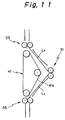
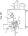
- FIGS. 29 and 30 another alternative embodiment of the present invention is shown which includes means for retracting the switch roller 21 and a linear third sheet transport path.
- the switching device has retracting means 60 for retracting the switch roller 21 from an operative or steering position to an inoperative or retracted position shown in FIG. 30.
- the switch roller 21 When the switch roller 21 is brought to the inoperative position by the retracting means 60, the sheet P coming out of the inlet roller pair 31 is transported along a linear path 61.
- the retracting means 60 retracts the switch roller 21 to below the path 61.
- the switch roller 21 contacts the lower surface of the sheet P being driven by the roller pair 31 and rotates in a direction indicated by an arrow in FIG. 30 to exert an auxiliary transporting force on the sheet P.
- the retracting means 60 includes a lever 63 rotatably supported by a pin 62 at substantially the center thereof.
- the switch roller 21 is mounted on one end of the lever 63 and reversibly rotated by a motor, not shown.
- a solenoid 64 has a plunger thereof connected to the other end of the lever 63.
- the solenoid 64 When the solenoid 64 is not energized, the lever 63 is biased by a spring 65 in a direction indicated by an arrow in FIG. 29.
- a stop not shown, stops the lever 63 at the position shown in FIG. 29 where it can steer sheets.
- the solenoid 64 When the solenoid 64 is turned on, it rotates the lever 63 about the pin 62 in a direction opposite to the direction A against the action of the spring 65. On reaching the inoperative position shown in FIG.
- a sheet discharge tray 66 is openable to stack sheets sequentially coming out of the linear path 61.
- the retracting means 60 selectively turns on or turns off the solenoid 64 in association with the opening or closing of the tray 66, thereby bringing the switch roller 21 to the inoperative position or the operative position.
- a switch 67 is mounted on the left side of the printer body 1, as viewed in FIG. 29.
- a controller turns on or turns off the solenoid 64.
- the switch 67 turns on or turns off when the tray 66 located at the outlet of the path 61 is opened or closed.
- the switch 67 and, therefore, the solenoid 64 is turned off to maintain the switch roller 21 in the operative or steering position.
- the switch 67 and, therefore, the solenoid 64 is turned off to move the switch roller 21 to the inoperative or retracted position. In this position, the switch roller 21 contacts the lower surface of the sheet P being transported by the inlet roller pair 31 along the linear path 61, exerting an auxiliary transporting force.
- the switch roller 21 is automatically moved to a particular position in association with the position of the tray 66, insuring accurate transport and discharge of sheets. Should the position of the switch roller 21 be switched over by an operation independent of the opening/closing of the tray 66, sheets might accidentally be steered to the linear path 61 having been closed by the tray 66.
- the three transport paths, including the linear path 61, available with the embodiment are useful in practice. Further, when retracted to below the path 61, the switch roller 21 contacts the lower surface of the sheet P being transported by the roller pair 31 along the path 61, thereby enhancing smooth sheet transport.
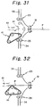
- FIGS. 31 and 32 show another alternative embodiment of the present invention similar to the embodiment of FIGS. 29 and 30 except that the switch roller 21 is replaced with the switch belt 41.
- the switch belt 41 is movable between an operative or steering position indicated by a phantom line and an inoperative or retracted position indicated by a solid line.
- retracting means similar to the retracting means 60 shown in FIG. 29.
- This embodiment is also successful in steering sheets P into the linear path 61, as desired.
- FIG. 32 when the switch belt 41 is brought to the retracted position, it contacts the lower surface of the sheet P being transported by the inlet roller pair 31 and rotates in a direction indicated by an arrow, thereby promoting smooth sheet transport.
- FIG. 33 shows another alternative embodiment of the present invention which includes a switch roller in the form of a brush roller 71.
- the switch roller 71 is provided with a configuration shown in FIG. 34 and is located at the junction of the paths 33 and 34, as shown in FIG. 33.
- FIG. 35 to steer the sheet P coming out of the fixing unit 19, FIG. 2, to the path 33, the switch roller 71 is rotated counterclockwise to beat the leading edge of the sheet P toward the path 33.
- FIG. 36 while the first sheet P1 is still in contact with the switch roller 71, the roller 71 is reversed to rotated clockwise.
- the reverse rotation of the switch roller 71 does not obstruct the transport of the sheet P1 since the sheet P1 has already been nipped and driven upward by the roller pair 23.
- the switch roller 71 beats it toward the path 34.
- the switch roller 71 again rotating counterclockwise steers it to the path 33.
- the brush-like switch roller 71 is capable of steering sheets smoothly without damaging them.
- the switch roller 71 may be replaced with a switch roller 81 made of foam rubber or sponge of low hardness.
- the switch roller 81 exerts greater friction than the switch roller 71 and, therefore, enhances sharp switchover.
- a switch roller 91 having blades thereon. The blades of the switch roller 91 generate a stream of air with the result that the sheet coming out of the fixing unit is cooled off. This promotes the fixation of the toner image on the sheet and, therefore, prevents the roller pairs downstream of the switch roller 91 from rubbing the toner image.
- FIG. 40 shows another alternative embodiment of the present invention capable of steering sheets to any one of three transport paths, as in the embodiment of FIG. 33.
- two (three or more, if desired) switch rollers 71A and 71B are provided for steering sheets P being driven by the inlet roller pair 31 to any one of the paths 33, 34 and 61, as needed.
- the switch rollers 71A and 71B are shown as comprising brush rollers, they may, of course, be implemented as any other type of rollers.
- the switch rollers 71A and 71B are rotated as indicated by arrows in FIG. 40.
- the switch rollers 71A and 71B are rotated as indicated by arrows in FIG. 41.
- the switch rollers 71A and 71B are rotated as indicated by arrows in FIG. 42.
- switch rollers 21, 71, 81 and 91 it is preferable to rotate the switch roller only for a period of time sufficient to guide the leading edge of the sheet P being transported by the inlet roller pair 31 in a desired direction.
- the switch roller will also be driven by a motor independent of the main motor.
- FIG. 43 is representative of a specific procedure which causes the switch roller to stop rotating at the time of switchover of the rotation direction.
- the motor for driving the switch roller is reversed and rotated for a predetermined period of time T.
- the motor is rotated clockwise (CW) for the period of time T to rotate the switch roller in the corresponding direction and then stopped.
- the motor is rotated counterclockwise (CCW) for the period of time T to reverse the rotation of the switch roller. Hence, the rotation of the motor is stabilized before the leading edge of the second sheet P2 arrives at the switch roller, insuring accurate switchover of the path even when the interval between consecutive sheets is extremely short.
- FIG. 44 is representative of another specific procedure using a motor capable of selectively rotating at a normal speed or a high speed.
- the switch roller (see roller 21, FIG. 1) is rotated at a peripheral speed Vf (high speed) higher than the linear velocity Vs (normal speed) of the sheet P being transported by the roller pair (see roller pair 31, FIG. 1) for a period of time necessary for the leading edge of the sheet P to be guided to a particular path.
- Vf high speed
- Vs normal speed
- the switch roller is rotated at a peripheral speed equal to the linear velocity Vs of the sheet P.
- the switch roller is rotated counterclockwise (CCW) after clockwise rotation (CW).
- the motor is rotated clockwise at the high speed (Vf) to in turn rotate the switch roller at a high speed.
- Vf high speed
- the motor and, therefore, the switch roller is rotated at the normal speed (Vs).
- the motor is driven counterclockwise (CCW) at the high speed (Vf) for the predetermined period of time T. In this manner, the sheet transport direction can be surely switched even if the switch roller is not brought to a stop.
- a one-sided image form mode or simplex mode and a two-sided image form mode or duplex mode are available with a printer or similar image forming apparatus. Therefore, it is necessary to control the sheet transport path switching device in a particular manner in each of the simple and duplex modes.
- the switch roller In the simplex mode, the switch roller should only be rotated in one direction.
- the switching device has to be operated by taking account of the number of sheets to be continuously fed to the duplex at the beginning of sheet feed in relation to the number of sheets to enter a transport path which terminates at the sheet inlet of the printer body.
- the switching device will also selects particular paths alternately. It follows that in the event of duplex printing the switching device can be efficiently controlled only if the control over the front/rear printing of sheets is directly applied.
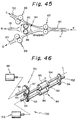
- FIG. 45 shows another alternative embodiment of the present invention which includes a switch roller pair 84 for selecting one of three different transport paths.
- FIG. 46 shows this embodiment in a perspective view. As shown in FIG. 45, a sheet P advancing a path 80 in a direction K is steered to one of three paths 131, 132 and 133 by the switch roller pair 84, i.e., switch rollers 85 and 86.
- First drive means 90 FIG. 46, rotates each of the rollers 85 and 86 in a direction indicated by an arrow, so that the rollers 85 and 86 may nip and transport the sheet P.
- Second drive means 100 FIG.
- the switch roller pair 84 rotates the entire switch roller pair 84 about a second drive axis 101 parallel to the roller axis L of the roller pair 84 in a forward direction or a reverse direction, as needed.
- the switch roller pair 84 nips and conveys the sheet P in a direction B shown in FIG. 45, guides the sheet P in a direction C with the periphery 84a thereof when bodily rotated in a direction E or forward direction, or guides the sheet P in a direction D with the periphery 84b thereof (identical with the periphery 84a) when bodily rotated in the other direction.
- a transport roller pair 87 is located at a position where the paths 132-133 branches off the path 80.
- Transport rollers 88 and 89 are respectively located on the path 132 downstream of the switch roller pair 84 and on the path 133 downstream of the switch roller pair 84.
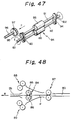
- the rollers 85 and 86 of the switch roller pair 84 are respectively mounted on shafts 104 and 92 which are integrally and rotatably supported by opposite support plates 93 and 94 via bearings, not shown.
- a gear 95 is mounted on one end of the shaft 104 while a drive gear 97 is mounted on the drive shaft 96 and capable of meshing with the gear 95. As shown in FIG.
- the drive shaft 96 is held by a support member, not shown, in such a manner as to be slidable in a direction indicated by an arrow F.
- the drive shaft 96 is driven by, for example, a solenoid to move between a position where the drive gear 97 meshes with the gear 95 (FIG. 46) and a position where the former does not mesh with the latter (FIG. 47).
- the drive shaft 96 with the drive gear 97 is affixed to the output shaft of a drive motor 98, FIG. 46.
- the drive motor 98 When the drive motor 98 is energized, it causes the roller 85 to rotate in a direction G with the result that the roller 86 is driven by the roller 85 in a direction J.
- the gear 95, drive gear 97 capable of meshing with the gear 95, drive shaft 96 and motor 98 constitute the first drive means 90.
- the drive means 90 causes the rollers 85 and 86 of the switch roller pair 84 to nip the sheet P coming out of the path 80, FIG. 45, and transport it in the direction B.
- a second drive shaft 101 extends outward from the center of the support plate 93.
- a drive shaft 102 extends out from the center of the other support plate 94 in alignment with the drive shaft 101.
- the drive shafts 101 and 102 are journalled to the framework of the device.
- a reversible drive motor 103 has the output shaft thereof connected to the drive shaft 101.
- the roller pair 84 guides the sheet P in the second direction C with the periphery 84a thereof, i.e., the locus of the outermost portions of the rollers 85 and 86.
- the roller pair 84 guides the sheet P in the direction D with the periphery 84b thereof (identical with the periphery 84a).
- the drive motor 103, second drive shaft 101, shaft 102 and opposite support plates 93 and 94 constitute the second drive means 100.
- the second drive means 100 causes the switch roller pair 84 to bodily rotate for guiding the sheet P to either of the directions C and D, as needed.
- the drive motor 103 is implemented by a stepping motor so as to locate the switch roller pair 84 at the home position of FIGS. 45 and 46 with ease.
- a home position sensor implemented as a transmission type photosensor or similar sensor, not shown, senses the drive gear 97 brought to a home position thereof where it meshes with the gear 95. This allows the drive gear 97 to surely mesh with the gear 95 at an accurate position.
- a mechanical stop for restricting the sliding movement of the drive gear 97 may be used.
- the entire switch roller pair 84 is held in the position shown in FIG. 48.
- the drive gear 97 is brought to the home position where it meshes with the gear 95.
- the drive motor 98 is energized to rotate the rollers 85 and 86 in directions indicated by arrows in FIG. 48.
- the rollers 85 and 86 nip and transport the sheet P to the path 131.
- the drive gear 97 is moved away from the gear 95 to make the rollers 85 and 86 free.
- the drive motor 103 of the second drive means 100 is rotated in the forward direction to rotate the entire switch roller pair 84 in the direction E, FIG. 45. Consequently, the switch roller pair 84 guides the sheet P to the path 132 by beating it upward, as viewed in the figure, with the periphery 84a thereof.
- the drive gear 97 is also brought out of mesh with the gear 95. Then, the drive motor 103 is rotated in the reverse direction to rotate the entire switch roller pair 84 in the direction opposite to the direction E. This causes the switch roller pair 84 to beat the sheet P downward with the periphery 84b thereof, thereby guiding it to the path 133.
- the rollers constituting the switch roller pair 84 guide the sheet P to desired one of the paths 131-133 stably without damaging it.
- the gears 95 and 97 it is preferable that the drive gear 97 is brought to the position shown in FIG. 46 or 47 in interlocked relation to the start or stop of rotation of the drive gear 96.
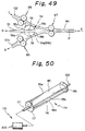
- FIG. 49 shows another alternative embodiment of the present invention which uses a sheet guide member 114 in place of the switch roller pair 84.
- the sheet guide member 114 is located in the vicinity of a position where the paths 131-133 branch off the path 80 and is made up of an upper and a lower guide plate 115 and 116.
- Drive means 110 causes the sheet guide member 114 to bodily rotate in either direction about the shaft 102 and a shaft 111, FIG. 50, which is substantially parallel to a sheet transport plane and perpendicular to the direction K.
- the shafts 102 and 111 are aligned with each other.
- the sheet guide member 114 When the sheet guide member 114 is bodily rotated in the direction E or forward direction, it guides the sheet P in the direction C with the periphery 114a thereof. When the sheet guide member 114 is bodily rotated in the direction opposite to the direction E, it guides the sheet P in the direction D with the periphery 114b thereof (identical with the periphery 114a).
- the peripheries 114a and 114b associated with the forward and reverse rotations, respectively, are defined by the locuses of the front edge 115a and rear edge 115b of the guide plate 115 and the front edge 116a and rear edge 116b of the guide plate 116 with respect to the sheet feed direction.
- the drive shaft 111 and shaft 102, FIG. 50, are positioned at the intermediate between the guide plates 115 and 116 in the vertical direction, so that such locuses substantially coincide with each other.
- the drive means 110 for reversibly rotating the entire sheet guide member 114 is constituted by retainer plates 117 and 118 supporting opposite ends of the guide plates 115 and 116 as well as by the shafts 111 and 102 and motor 103.
- the shaft 111 is affixed to the retainer plate 117 at the outside of the center of the plate 117 while the shaft 102 is affixed to the retainer plate 118 at the outside of the center of the plate 118.
- the entire sheet guide member 114 In operation, to steer the sheet P coming out of the path 80 to the path 131, the entire sheet guide member 114 is held in the stop position shown in FIG. 49. As shown in FIG. 49, to steer the sheet P to the path 132, the drive motor 103 of the drive means 110 is rotated in the forward direction to rotate the entire sheet guide member 114 in the direction E, FIG. 49. Consequently, the sheet guide member 114 guides the sheet P to the path 132 by beating it upward, as viewed in the figure, with the periphery 114a thereof. Further, to transport the sheet P to the path 133, the drive gear 97 is also brought out of mesh with the gear 95.
- the drive motor 103 is rotated in the reverse direction to rotate the entire sheet guide member 114 84 in the direction opposite to the direction E. This causes the sheet guide member to beat the sheet P downward with the periphery 114b thereof, thereby guiding it to the path 133.
- a home position sensor or similar implementation may be used to determine the angular position of the member 114 and stop the drive motor 103 at the illustrated position.
- a mechanical stop mechanism may be used to forcibly stop the sheet guide member 114 at the illustrated position and then deenergize the motor 103.
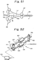
- the sheet guide member may be constituted by a single guide plate 116 (or 115) located slightly below (or slightly above in the case of the guide plate 115) a line La on which the sheet P is transported.
- This single guide plate scheme is comparable with the above-stated double guide plate scheme in respect of advantages.
- FIG. 52 shows another alternative embodiment of the present invention similar to the embodiment of FIGS. 49 and 50 except that the sheet guide member 114 is replaced with a sheet guide member 124 in the form of two parallel spaced rollers 125 and 126.
- the rollers 125 and 126 are rotatably mounted on shafts 127 and 128, respectively.
- the shafts 127 and 128 are affixed to support plates 121 and 122 at opposite ends thereof.
- the drive shaft 111 and the shaft 102 extend outward from the centers of the support plates 121 and 122, respectively.
- the drive shaft 111 is reversibly rotated by the motor 103 to rotate the entire sheet guide member 124 in the direction E or the other direction, as needed.
- the sheet guide member 124 guides the sheet in the second direction C, FIG. 49, or the third direction P, FIG. 49, with the periphery 124a or 124b thereof, it is prevented from damaging the sheet more surely than in the embodiment of FIG. 49.
- FIGS. 53A-53E another alternative embodiment of the present invention is shown which is capable of selecting a particular path for sheets which are transported at high speed. Briefly, this embodiment performs patch switchover for the sheet P2 following the sheet P1 before the trailing edge Pb of the sheet P1 moves away from the switch roller pair 84. This will be described specifically on the assumption that after the sheet P1 has been steered to the path 131, FIG. 45, the next sheet P2 is steered to the path 132, FIG. 45.
- the transport roller pair 87 moves the sheet P1 in the direction K.
- the rollers 85 and 86 of the switch roller pair 84 nip the sheet P1 and drive it to the path 131 (see FIG. 45).
- the switch roller pair 84 is bodily rotated in the direction E, as shown in FIG. 53B.
- the rollers 85 and 86 are free to rotate since the drive gear 97, FIG. 47, has already been brought out of mesh with the gear 95, FIG. 47.
- FIG. 53A the transport roller pair 87 moves the sheet P1 in the direction K.
- the rollers 85 and 86 of the switch roller pair 84 nip the sheet P1 and drive it to the path 131 (see FIG. 45).
- the switch roller pair 84 is bodily rotated in the direction E, as shown in FIG. 53B.
- the rollers 85 and 86 are free to rotate since the drive gear 97, FIG. 47, has already been brought out of mesh with the gear 95, FIG. 47.
- the embodiment switches over the path for the succeeding sheet P2 before the trailing edge of the preceding sheet P1 moves away from the switch roller pair 84.
- the embodiment can, therefore, surely guide sheets to desired paths even when the interval between the consecutive sheets is extremely short due to high speed transport. It has been customary to replace a transport path by changing the positions of, for example, pawls when the interval between consecutive sheets arrives at the branching point. With this conventional scheme, it is impossible to switch over the path when sheets are continuously fed at an extremely short internal for efficient image formation.
- the present invention provides a sheet transport path switching device having various unprecedented advantages, as enumerated below.
Landscapes
- Engineering & Computer Science (AREA)
- Mechanical Engineering (AREA)
- Separation, Sorting, Adjustment, Or Bending Of Sheets To Be Conveyed (AREA)
- Counters In Electrophotography And Two-Sided Copying (AREA)
- Paper Feeding For Electrophotography (AREA)
Applications Claiming Priority (6)
| Application Number | Priority Date | Filing Date | Title |
|---|---|---|---|
| JP7963092 | 1992-04-01 | ||
| JP79630/92 | 1992-04-01 | ||
| JP11613092 | 1992-05-08 | ||
| JP116130/92 | 1992-05-08 | ||
| JP12431/93 | 1993-01-28 | ||
| JP01243193A JP3257712B2 (ja) | 1992-04-01 | 1993-01-28 | 搬送路切換装置 |
Publications (3)
| Publication Number | Publication Date |
|---|---|
| EP0564291A2 EP0564291A2 (en) | 1993-10-06 |
| EP0564291A3 EP0564291A3 (es) | 1994-01-19 |
| EP0564291B1 true EP0564291B1 (en) | 1996-11-27 |
Family
ID=27279828
Family Applications (1)
| Application Number | Title | Priority Date | Filing Date |
|---|---|---|---|
| EP93302589A Expired - Lifetime EP0564291B1 (en) | 1992-04-01 | 1993-04-01 | Sheet transport path switching device for an image forming apparatus |
Country Status (4)
| Country | Link |
|---|---|
| EP (1) | EP0564291B1 (es) |
| JP (1) | JP3257712B2 (es) |
| DE (1) | DE69306151T2 (es) |
| ES (1) | ES2095007T3 (es) |
Families Citing this family (12)
| Publication number | Priority date | Publication date | Assignee | Title |
|---|---|---|---|---|
| JPH082775A (ja) * | 1994-06-14 | 1996-01-09 | Ricoh Co Ltd | 排紙装置 |
| JP3465032B2 (ja) * | 1994-07-21 | 2003-11-10 | コニカミノルタホールディングス株式会社 | 画像形成装置 |
| US6341777B1 (en) * | 2000-03-02 | 2002-01-29 | Xerox Corporation | Multiple-position idler roller |
| GB0114523D0 (en) * | 2001-06-14 | 2001-08-08 | Rue De Int Ltd | Sheet diverting assembly |
| KR100445343B1 (ko) * | 2002-05-10 | 2004-08-25 | (주)케이알디씨 | 용지경로변경장치 |
| JP2006199452A (ja) * | 2005-01-21 | 2006-08-03 | Kyocera Mita Corp | シート搬送装置及びそれを備えた画像形成装置 |
| EP1847493B1 (en) * | 2006-04-19 | 2016-10-05 | Ricoh Company, Ltd. | Sheet conveying apparatus |
| JP4837592B2 (ja) * | 2006-05-29 | 2011-12-14 | 株式会社リコー | 記録媒体搬送装置および画像形成装置 |
| KR100915269B1 (ko) * | 2008-09-01 | 2009-09-03 | 이계설 | 리튬 이온전지의 분리막 연결장치 및 방법 |
| IT1395806B1 (it) * | 2009-09-24 | 2012-10-26 | C M C Srl | Sistema per indirizzare articoli in foglio da una linea di ingresso verso due linee di uscita |
| US8196926B2 (en) * | 2009-11-06 | 2012-06-12 | Goss International Americas, Inc. | Apparatus for electronically diverting signatures |
| JP6862137B2 (ja) | 2016-09-30 | 2021-04-21 | キヤノン株式会社 | シート搬送装置、画像形成装置 |
Family Cites Families (8)
| Publication number | Priority date | Publication date | Assignee | Title |
|---|---|---|---|---|
| JPS4725453Y1 (es) * | 1970-11-11 | 1972-08-08 | ||
| JPS5576318U (es) * | 1978-11-21 | 1980-05-26 | ||
| JPS57203648A (en) * | 1981-06-09 | 1982-12-14 | Canon Inc | Sheet branch device |
| JPS6052455A (ja) | 1983-08-30 | 1985-03-25 | Fuji Xerox Co Ltd | 用紙経路切換え装置 |
| DE8717500U1 (de) * | 1987-10-19 | 1988-12-08 | Jagenberg AG, 4000 Düsseldorf | Bänderschleuse für Zuschnitte aus steifem Material, insbesondere zusammengelegte Faltschachteln |
| JPH02105830A (ja) * | 1988-10-14 | 1990-04-18 | Osaka Gas Co Ltd | 炭素繊維製組紐の製造方法 |
| US5049947A (en) * | 1989-07-03 | 1991-09-17 | Xerox Corporation | Rotating brush decision gate |
| JPH04368549A (ja) * | 1991-06-18 | 1992-12-21 | Mitsui Constr Co Ltd | 構造用材料 |
-
1993
- 1993-01-28 JP JP01243193A patent/JP3257712B2/ja not_active Expired - Fee Related
- 1993-04-01 ES ES93302589T patent/ES2095007T3/es not_active Expired - Lifetime
- 1993-04-01 EP EP93302589A patent/EP0564291B1/en not_active Expired - Lifetime
- 1993-04-01 DE DE69306151T patent/DE69306151T2/de not_active Expired - Fee Related
Also Published As
| Publication number | Publication date |
|---|---|
| EP0564291A3 (es) | 1994-01-19 |
| DE69306151D1 (de) | 1997-01-09 |
| JP3257712B2 (ja) | 2002-02-18 |
| ES2095007T3 (es) | 1997-02-01 |
| JPH0624620A (ja) | 1994-02-01 |
| DE69306151T2 (de) | 1997-04-17 |
| EP0564291A2 (en) | 1993-10-06 |
Similar Documents
| Publication | Publication Date | Title |
|---|---|---|
| US6619657B2 (en) | Curl correction device, and image forming apparatus having the curl correction device | |
| JP2000229758A (ja) | カール補正装置、画像形成装置 | |
| US20030063936A1 (en) | Duplex image forming apparatus | |
| EP0564291B1 (en) | Sheet transport path switching device for an image forming apparatus | |
| KR100622401B1 (ko) | 화상형성장치의 용지역전장치 | |
| US7876479B2 (en) | Automatic document feeder and image forming apparatus having the same | |
| EP0679962B1 (en) | Double-side image forming apparatus and reverse sheet feeding device | |
| JP5738384B2 (ja) | シートのカール矯正装置及び画像形成装置 | |
| US8328195B2 (en) | Exit path assembly for an imaging device | |
| JPH04327447A (ja) | 両面印字用の用紙搬送装置 | |
| EP1001317B1 (en) | Double sided printing apparatus | |
| JP3999057B2 (ja) | 整合装置、および、それを備えた画像形成システム | |
| JPH10129912A (ja) | 用紙反転装置 | |
| JP3358409B2 (ja) | 画像形成装置 | |
| JP3904041B2 (ja) | 電子写真装置 | |
| JP2003292221A (ja) | 画像形成装置 | |
| JP2001253622A (ja) | シート搬送装置及び画像形成装置 | |
| JP2000229760A (ja) | 画像形成システム、カール補正装置 | |
| JP4193548B2 (ja) | 画像形成装置及びそれに装着可能な反転搬送ユニット | |
| JP2864971B2 (ja) | 両面印刷装置 | |
| JP3177427B2 (ja) | シート搬送装置及びシート処理装置 | |
| JPH04323161A (ja) | シート搬送装置 | |
| JPH1036014A (ja) | 両面印刷装置 | |
| JP3755275B2 (ja) | 画像形成装置における画像形成対象シート搬送装置 | |
| JP2001097622A (ja) | 画像形成装置 |
Legal Events
| Date | Code | Title | Description |
|---|---|---|---|
| PUAI | Public reference made under article 153(3) epc to a published international application that has entered the european phase |
Free format text: ORIGINAL CODE: 0009012 |
|
| AK | Designated contracting states |
Kind code of ref document: A2 Designated state(s): DE ES FR GB IT |
|
| PUAL | Search report despatched |
Free format text: ORIGINAL CODE: 0009013 |
|
| AK | Designated contracting states |
Kind code of ref document: A3 Designated state(s): DE ES FR GB IT |
|
| 17P | Request for examination filed |
Effective date: 19940112 |
|
| 17Q | First examination report despatched |
Effective date: 19950511 |
|
| GRAG | Despatch of communication of intention to grant |
Free format text: ORIGINAL CODE: EPIDOS AGRA |
|
| GRAH | Despatch of communication of intention to grant a patent |
Free format text: ORIGINAL CODE: EPIDOS IGRA |
|
| GRAH | Despatch of communication of intention to grant a patent |
Free format text: ORIGINAL CODE: EPIDOS IGRA |
|
| GRAA | (expected) grant |
Free format text: ORIGINAL CODE: 0009210 |
|
| AK | Designated contracting states |
Kind code of ref document: B1 Designated state(s): DE ES FR GB IT |
|
| ITF | It: translation for a ep patent filed | ||
| REF | Corresponds to: |
Ref document number: 69306151 Country of ref document: DE Date of ref document: 19970109 |
|
| ET | Fr: translation filed | ||
| REG | Reference to a national code |
Ref country code: ES Ref legal event code: FG2A Ref document number: 2095007 Country of ref document: ES Kind code of ref document: T3 |
|
| PLBE | No opposition filed within time limit |
Free format text: ORIGINAL CODE: 0009261 |
|
| STAA | Information on the status of an ep patent application or granted ep patent |
Free format text: STATUS: NO OPPOSITION FILED WITHIN TIME LIMIT |
|
| 26N | No opposition filed | ||
| REG | Reference to a national code |
Ref country code: GB Ref legal event code: IF02 |
|
| PGFP | Annual fee paid to national office [announced via postgrant information from national office to epo] |
Ref country code: ES Payment date: 20090513 Year of fee payment: 17 |
|
| PGFP | Annual fee paid to national office [announced via postgrant information from national office to epo] |
Ref country code: IT Payment date: 20090421 Year of fee payment: 17 Ref country code: FR Payment date: 20090417 Year of fee payment: 17 Ref country code: DE Payment date: 20090327 Year of fee payment: 17 |
|
| PGFP | Annual fee paid to national office [announced via postgrant information from national office to epo] |
Ref country code: GB Payment date: 20090401 Year of fee payment: 17 |
|
| GBPC | Gb: european patent ceased through non-payment of renewal fee |
Effective date: 20100401 |
|
| REG | Reference to a national code |
Ref country code: FR Ref legal event code: ST Effective date: 20101230 |
|
| PG25 | Lapsed in a contracting state [announced via postgrant information from national office to epo] |
Ref country code: DE Free format text: LAPSE BECAUSE OF NON-PAYMENT OF DUE FEES Effective date: 20101103 |
|
| PG25 | Lapsed in a contracting state [announced via postgrant information from national office to epo] |
Ref country code: GB Free format text: LAPSE BECAUSE OF NON-PAYMENT OF DUE FEES Effective date: 20100401 Ref country code: IT Free format text: LAPSE BECAUSE OF NON-PAYMENT OF DUE FEES Effective date: 20100401 |
|
| REG | Reference to a national code |
Ref country code: ES Ref legal event code: FD2A Effective date: 20110715 |
|
| PG25 | Lapsed in a contracting state [announced via postgrant information from national office to epo] |
Ref country code: ES Free format text: LAPSE BECAUSE OF NON-PAYMENT OF DUE FEES Effective date: 20110705 |
|
| PG25 | Lapsed in a contracting state [announced via postgrant information from national office to epo] |
Ref country code: ES Free format text: LAPSE BECAUSE OF NON-PAYMENT OF DUE FEES Effective date: 20100402 |
|
| PG25 | Lapsed in a contracting state [announced via postgrant information from national office to epo] |
Ref country code: FR Free format text: LAPSE BECAUSE OF NON-PAYMENT OF DUE FEES Effective date: 20100430 |