EP0563719A2 - Méthode et dispositif de modulation numérique - Google Patents
Méthode et dispositif de modulation numérique Download PDFInfo
- Publication number
- EP0563719A2 EP0563719A2 EP93104616A EP93104616A EP0563719A2 EP 0563719 A2 EP0563719 A2 EP 0563719A2 EP 93104616 A EP93104616 A EP 93104616A EP 93104616 A EP93104616 A EP 93104616A EP 0563719 A2 EP0563719 A2 EP 0563719A2
- Authority
- EP
- European Patent Office
- Prior art keywords
- switch
- modulator
- time interval
- pulses
- calculated
- Prior art date
- Legal status (The legal status is an assumption and is not a legal conclusion. Google has not performed a legal analysis and makes no representation as to the accuracy of the status listed.)
- Granted
Links
- 238000000034 method Methods 0.000 title claims abstract description 39
- 230000015654 memory Effects 0.000 claims description 16
- 238000004364 calculation method Methods 0.000 claims description 15
- 230000006870 function Effects 0.000 claims description 9
- 230000033228 biological regulation Effects 0.000 claims description 8
- 238000004088 simulation Methods 0.000 claims description 6
- 230000009467 reduction Effects 0.000 abstract description 2
- 230000001131 transforming effect Effects 0.000 abstract 1
- 238000005070 sampling Methods 0.000 description 15
- 230000008569 process Effects 0.000 description 10
- 230000006399 behavior Effects 0.000 description 5
- 238000010586 diagram Methods 0.000 description 5
- 238000001208 nuclear magnetic resonance pulse sequence Methods 0.000 description 5
- 230000008859 change Effects 0.000 description 4
- 230000007704 transition Effects 0.000 description 4
- 230000000694 effects Effects 0.000 description 3
- 230000008901 benefit Effects 0.000 description 2
- 230000002349 favourable effect Effects 0.000 description 2
- 230000010363 phase shift Effects 0.000 description 2
- 230000004044 response Effects 0.000 description 2
- 230000003321 amplification Effects 0.000 description 1
- 230000003139 buffering effect Effects 0.000 description 1
- 230000001934 delay Effects 0.000 description 1
- 230000001419 dependent effect Effects 0.000 description 1
- 230000006866 deterioration Effects 0.000 description 1
- 238000005516 engineering process Methods 0.000 description 1
- 230000014759 maintenance of location Effects 0.000 description 1
- 230000007246 mechanism Effects 0.000 description 1
- 238000003199 nucleic acid amplification method Methods 0.000 description 1
- 230000002123 temporal effect Effects 0.000 description 1
- 230000001960 triggered effect Effects 0.000 description 1
Images

Classifications
-
- H—ELECTRICITY
- H03—ELECTRONIC CIRCUITRY
- H03K—PULSE TECHNIQUE
- H03K7/00—Modulating pulses with a continuously-variable modulating signal
- H03K7/10—Combined modulation, e.g. rate modulation and amplitude modulation
-
- B—PERFORMING OPERATIONS; TRANSPORTING
- B64—AIRCRAFT; AVIATION; COSMONAUTICS
- B64G—COSMONAUTICS; VEHICLES OR EQUIPMENT THEREFOR
- B64G1/00—Cosmonautic vehicles
- B64G1/22—Parts of, or equipment specially adapted for fitting in or to, cosmonautic vehicles
- B64G1/24—Guiding or controlling apparatus, e.g. for attitude control
- B64G1/244—Spacecraft control systems
-
- B—PERFORMING OPERATIONS; TRANSPORTING
- B64—AIRCRAFT; AVIATION; COSMONAUTICS
- B64G—COSMONAUTICS; VEHICLES OR EQUIPMENT THEREFOR
- B64G1/00—Cosmonautic vehicles
- B64G1/22—Parts of, or equipment specially adapted for fitting in or to, cosmonautic vehicles
- B64G1/24—Guiding or controlling apparatus, e.g. for attitude control
- B64G1/26—Guiding or controlling apparatus, e.g. for attitude control using jets
Definitions
- the invention relates to a digital modulation method according to the preamble of claim 1 and an associated digital modulator and a control device using such a modulator.
- ON / OFF operating states such as flow control valves, reaction engines, metering mechanisms, temperature control switches, three-point switching elements, solenoids and the like
- pulses are triggered whose pulse width, pulse frequency and / or pulse-time area follow the reference variable according to predetermined laws and this is in particular directly proportional.
- modulators of various variants are generally used, such as pulse width modulators, pulse frequency modulators, pulse width pulse frequency modulators (PWPF) or pseudo rate modulators.
- PWPF pulse width pulse frequency modulators
- PWPF pulse width pulse frequency modulators
- pseudo rate modulators For technical applications in closed control loops, not only the shape of the pulse train and its proportionality to the corresponding input signal, but also its phase position with regard to the temporal change in the command signal is of crucial importance, since the stability and dynamic behavior of a control loop and thus the quality of a control process depend crucially on it. Since, as is well known, all the physical systems (controlled systems) to be controlled that occur in practice have a delay character, i.e.
- Pseudo-rate modulators that generate an output signal that is not only proportional to the amplitude-time area of the input signal, but also its rate of change (pseudo-rate). If other types of modulator are used, additional, pre-generating controller networks would have to be used to generate the same stability properties of a control loop in order to obtain the corresponding positive phase angle, which would, however, result in a deterioration in the signal-to-noise ratio and additional implementation effort.
- a method of the type mentioned is known from US-A1 4,599,697.
- a position control method for satellites based on the use of digital PWPF modulation is described there.
- the satellite represents the controlled system, the controlled variables are positional angles around the three satellite axes.
- Measuring elements in the form of earth and sun sensors and gyroscopes measure the actual values of the position angle and angular velocities.
- a controller determines control deviations from predeterminable target values and generates error signals in the form of digital sampling values, which remain constant over the duration of each of a series of successive time intervals (sampling periods), but are overall variable over time.
- output signals are generated which represent a sequence of positive and / or negative pulses of constant amplitude and variable pulse width and frequency. It is a simulation method in which each sampling period is divided into a fixed time grid and the modulator output signals are calculated for all resulting equidistant times. These calculations each take up part of the sampling period, and the calculated pulse sequence is called up in the next sampling interval and used to actuate actuators that supply discrete control pulses, e.g. Position control nozzles used to keep the controlled variables of the controlled system, namely the position angles, at the desired values.
- discrete control pulses e.g. Position control nozzles used to keep the controlled variables of the controlled system, namely the position angles, at the desired values.
- This known simulation method has the disadvantage that the real switching times of an analog modulator, whose behavior is to be reproduced digitally, are not exactly met due to the fixed time grid for each sampling period, and that a high computing effort is also required because many computing cycles between the switching points to be completed, the result of which is only that the simulated output signal does not change its state.
- Both disadvantages influence each other in the opposite direction, ie if the accuracy of the switching point determination can be increased with the help of a closer one Nesting of the time grid and thus an increase in the number of computing cycles for a sampling period simultaneously increases the computing effort and vice versa.
- the invention is therefore based on the object of designing a method of the type mentioned at the outset in such a way that a reduction in the computational effort while at the same time increasing the accuracy of the switching point determination results.
- a digital modulator for carrying out such a method and a control device using such a digital modulator must be specified.
- the switch-on and switch-off times of the pulses and their signs are therefore to be calculated in one go for each time interval (sampling period).
- the principle of simulating the behavior of an analog modulator is thus abandoned.
- the calculation (operation cycle) to be carried out again at the beginning of each new time interval takes place at very high speed within a very short period of time in comparison with the duration of the time interval, so that the entire pulse sequence valid for the current time interval is available right at the beginning.
- the corresponding calculations are carried out in a computing device which contains arithmetic units, memories and comparators.
- the computing device is also supplied with modulator parameters which identify the type of analog modulator to be simulated.
- the advantage of the method according to the invention is, above all, that a very precise calculation of the switching times is possible, the overall computational effort required being significantly reduced compared to the known simulation method.
- the output signals of the computing device can be stored until the entire pulse sequence to be assigned to a time interval is present. This memory can then be read with any accuracy with regard to the clock frequency to be used.
- Fig. 1 shows a control device which is used in the position control of satellites.
- the satellite itself is shown as controlled system 1. It should be stabilized with regard to its orientation in space, for which purpose the angular positions with respect to rotations around its satellite-fixed coordinate axes are to be kept at predefinable target values.
- there are initially measuring elements 2 which measure the position angles and, if appropriate, also the angular velocities about the axes mentioned.
- controller 3 where the control deviations from the setpoints are determined and error signals are generated according to the individual control rules.
- These can be continuously variable, but in the case of digital control they are output as discrete sample values, which are constant over the duration of each of a series of successive time intervals (sampling periods), but can be subject to changes over time over a longer period of time.
- the error signals are fed as input signals to a modulator 4, which has the task of providing output signals which represent a sequence of discrete, positive and / or negative pulses of constant amplitude and variable pulse width and frequency.
- These output signals are optionally used after buffering in a downstream memory 5 to control an actuating device 6, which emit discrete actuating pulses to the controlled system 1, specifically, for example, to position control nozzles or reaction wheels that are carried by the satellite.
- the control variables i.e. the above Position angle, are kept at the desired setpoints.
- FIG. 2 shows the functional circuit diagram of a pseudo-rate modulator, which essentially consists of a three-point hysteresis element 12 in the forward branch and a linear delay element of the first order 13 in the feedback branch and a summation element 11, in which a feedback signal r (t) is subtracted from an input signal e (t).
- the output signal i is fed back via the delay element 13 having an amplification factor K M and a time constant T M and reaches the summation element 11 as a feedback signal r (t).
- an input signal e k which is constant during each sampling period ⁇ t k is present .
- the modulator shown in FIG. 2 is of the pseudo rate type, since the delay element 13 is located in the feedback branch.
- a pseudo-rate modulator in a frequency range dependent on the parameters K M and T M ) generates a phase lead with respect to the input signal, an effect which is particularly desirable in the present case.
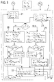
- FIG. 3 shows a functional circuit diagram of a modulation method according to the invention, by means of which a pseudo rate modulator is digitally simulated.
- data memories 21 to 23, comparators 25 to 27 and arithmetic units 28 to 33 are provided for performing the method, which form the essential elements of a computing device (modulator 4). Additional components required for executing digital processes, such as clock generators, computing registers and storage elements in the computing units, are not shown separately.
- each time interval .DELTA.t k (sampling period) located at the entrance of the modulator 4, the constant for the duration of this time interval the input signal e k to (k is the serial number of the k-th time interval).
- an additional calculation cycle will be necessary to determine that the last switching point calculated would already fall in the next time interval ⁇ t k + 1 and is therefore no longer part of the current sequence.
- the first switch-on time t se is calculated in a first arithmetic unit 28, based on the beginning of the time interval ⁇ t k . This is done according to the following rules: where h s1 and a s1 auxiliary variables, ⁇ t s1 the period until the switch-on time t se , h1 and T M mean modulator parameters already mentioned and ln the natural logarithm.
- the first switch-on time t se including the associated sign [sign (e k )!], Has thus been determined, and it must now be calculated when the corresponding pulse is to be switched off again. This is done as follows:
- the state variables i s and r s are transferred to a buffer store 23, which serves as an initial value store for the subsequent computing cycle.
- the state variables i s and r s valid for the end of the current time interval ⁇ t k are still closed calculate, using a transition function ⁇ according to the regulation for the one possible case that the last calculated switching time, which no longer falls within the time interval ⁇ t k, was a switch-on time t se (t se > ⁇ t k ), and according to the regulation for the other possible case that this last calculated time was a switch-off time t sa (t sa > ⁇ t k ).
- the switching state initiated at the previously calculated switching time is maintained.
- the state variables i s and r s according to (6) or (7) applicable to the end of the current operation cycle and thus also to the end of the time interval ⁇ t k are then read into the second data memory 22 and at the beginning of the following time interval ⁇ t k + 1 as new initial values in place of the quantities i k and r k in the first data memory 21.
- the system-related modulator parameters such as response and switch-off thresholds (h 1, h 2), modulator gain (K M ) and delay time constants (T M ) as a function of external signals or internal operating states of a higher-level control loop are adaptable.
- This can be done, for example, by transferring said parameters from a read-only memory (ROM) into a read-write memory (RAM) when the digital modulation device is switched on or when calling up one of these equivalent subroutines, which adaptively adopts new values via external data connections which can replace the old ones.
- ROM read-only memory
- RAM read-write memory
- This ensures that usable parameter values are available at all times, even if there is no external data input, which do not guarantee optimal behavior of the associated higher-level control loop or process, but at least ensure proper functioning.
- the maximum number of computing cycles required to determine all switch-on and switch-off times is to be specified in order to determine the switching states over the entire duration of a predetermined time or sampling interval ⁇ t k .
- This is important because the reading process of the calculated pulse sequence can only begin when its determination has been completed and the sequence control of digital processes takes place in fixed time frames.
- the number of switching states in a predetermined time interval ⁇ t k will therefore not exceed the closest integer number below the value 2t A / T min .
- the calculable step for the transition of the internal modulator state variables at the end of the sampling interval must then be added to the number of computing cycles that can be determined in this way for determining the switching states.
Landscapes
- Engineering & Computer Science (AREA)
- Remote Sensing (AREA)
- Chemical & Material Sciences (AREA)
- Combustion & Propulsion (AREA)
- Radar, Positioning & Navigation (AREA)
- Aviation & Aerospace Engineering (AREA)
- Automation & Control Theory (AREA)
- Feedback Control In General (AREA)
- Gyroscopes (AREA)
Applications Claiming Priority (2)
| Application Number | Priority Date | Filing Date | Title |
|---|---|---|---|
| DE4210966 | 1992-04-02 | ||
| DE4210966A DE4210966C2 (de) | 1992-04-02 | 1992-04-02 | Verfahren zur digitalen Modulation |
Publications (3)
| Publication Number | Publication Date |
|---|---|
| EP0563719A2 true EP0563719A2 (fr) | 1993-10-06 |
| EP0563719A3 EP0563719A3 (en) | 1995-03-15 |
| EP0563719B1 EP0563719B1 (fr) | 2000-12-20 |
Family
ID=6455814
Family Applications (1)
| Application Number | Title | Priority Date | Filing Date |
|---|---|---|---|
| EP93104616A Expired - Lifetime EP0563719B1 (fr) | 1992-04-02 | 1993-03-20 | Méthode de modulation numérique |
Country Status (4)
| Country | Link |
|---|---|
| US (1) | US5473633A (fr) |
| EP (1) | EP0563719B1 (fr) |
| JP (1) | JP2929567B2 (fr) |
| DE (2) | DE4210966C2 (fr) |
Cited By (1)
| Publication number | Priority date | Publication date | Assignee | Title |
|---|---|---|---|---|
| EP0861784A3 (fr) * | 1997-01-31 | 1998-11-11 | Space Systems/Loral, Inc. | Méthode et appareil de contrÔle d'attitude d'un véhicule spatial |
Families Citing this family (7)
| Publication number | Priority date | Publication date | Assignee | Title |
|---|---|---|---|---|
| US5684805A (en) * | 1995-11-30 | 1997-11-04 | Brown; Anthony Kevin Dale | Microwave multiphase detector |
| WO1998028847A1 (fr) * | 1996-12-23 | 1998-07-02 | Dsc Communications A/S | Procede et circuit pour le transfert de donnees |
| DE19931824B4 (de) * | 1999-07-08 | 2012-03-15 | Robert Bosch Gmbh | Verfahren und Vorrichtung zur Ausgabe eines pulsweitenmodulierten Signals |
| US20100098399A1 (en) * | 2008-10-17 | 2010-04-22 | Kurt Breish | High intensity, strobed led micro-strip for microfilm imaging system and methods |
| CN103029851B (zh) * | 2012-11-30 | 2015-04-22 | 北京控制工程研究所 | 一种参数自整定伪速率调制器 |
| FR3029661B1 (fr) * | 2014-12-04 | 2016-12-09 | Stmicroelectronics Rousset | Procedes de transmission et de reception d'un signal binaire sur un lien serie, en particulier pour la detection de la vitesse de transmission, et dispositifs correspondants |
| CN106125748B (zh) * | 2016-07-19 | 2018-11-23 | 北京控制工程研究所 | 一种伪速率喷气控制系统参数确定方法 |
Citations (3)
| Publication number | Priority date | Publication date | Assignee | Title |
|---|---|---|---|---|
| EP0046151A1 (fr) * | 1980-08-19 | 1982-02-24 | Messerschmitt-Bölkow-Blohm Gesellschaft mit beschränkter Haftung | Dispositif de commande d'attitude de véhicules élastiques |
| EP0101302A2 (fr) * | 1982-08-11 | 1984-02-22 | Ford Aerospace & Communications Corporation | Système de commande de l'attitude d'un vaisseau spacial |
| FR2546688A1 (fr) * | 1983-05-27 | 1984-11-30 | Messerschmitt Boelkow Blohm | Modulateur numerique d'impulsions en largeur et en frequence |
Family Cites Families (9)
| Publication number | Priority date | Publication date | Assignee | Title |
|---|---|---|---|---|
| US4001728A (en) * | 1974-02-27 | 1977-01-04 | The United States Of America As Represented By The Secretary Of The Navy | Digital method of pulse width modulation |
| US4138632A (en) * | 1977-04-04 | 1979-02-06 | Pneumo Corporation | Pulse width modulator digital servo system |
| US4646321A (en) * | 1984-08-31 | 1987-02-24 | Raytheon Company | Interpolation pulse duration modulated adder |
| JPS61133403A (ja) * | 1984-12-03 | 1986-06-20 | Nippon Denso Co Ltd | 電磁作動器駆動装置 |
| JP2504751B2 (ja) * | 1986-09-06 | 1996-06-05 | 勤 氏家 | 切断処理装置 |
| DE3885883D1 (de) * | 1987-09-16 | 1994-01-05 | Deutsche Aerospace | Vorrichtung zur sollwertregelung und/oder stabilisierung von freibeweglichen körpern mit gespeichertem drall. |
| JP2790808B2 (ja) * | 1987-12-15 | 1998-08-27 | 株式会社リコー | 音声認識装置 |
| JPH0374176A (ja) * | 1989-08-11 | 1991-03-28 | Fujitsu General Ltd | Pwm波形出力方法 |
| DE3926599A1 (de) * | 1989-08-11 | 1991-02-14 | Bodenseewerk Geraetetech | Schaltungsanordnung fuer die analogsignal-frequenz-wandlung |
-
1992
- 1992-04-02 DE DE4210966A patent/DE4210966C2/de not_active Expired - Fee Related
-
1993
- 1993-03-20 EP EP93104616A patent/EP0563719B1/fr not_active Expired - Lifetime
- 1993-03-20 DE DE59310129T patent/DE59310129D1/de not_active Expired - Fee Related
- 1993-03-30 JP JP5072287A patent/JP2929567B2/ja not_active Expired - Fee Related
- 1993-04-02 US US08/042,269 patent/US5473633A/en not_active Expired - Fee Related
Patent Citations (3)
| Publication number | Priority date | Publication date | Assignee | Title |
|---|---|---|---|---|
| EP0046151A1 (fr) * | 1980-08-19 | 1982-02-24 | Messerschmitt-Bölkow-Blohm Gesellschaft mit beschränkter Haftung | Dispositif de commande d'attitude de véhicules élastiques |
| EP0101302A2 (fr) * | 1982-08-11 | 1984-02-22 | Ford Aerospace & Communications Corporation | Système de commande de l'attitude d'un vaisseau spacial |
| FR2546688A1 (fr) * | 1983-05-27 | 1984-11-30 | Messerschmitt Boelkow Blohm | Modulateur numerique d'impulsions en largeur et en frequence |
Non-Patent Citations (1)
| Title |
|---|
| JOURNAL OF GUIDANCE, CONTROL AND DYNAMICS, Bd.13, Nr.6, November 1990, WASHINGTON,DC,US Seiten 1014 - 1022 T. C. ANTHONY ET AL.: 'Pulse-Modulated Control Synthesis for a Flexible Spacecraft' * |
Cited By (2)
| Publication number | Priority date | Publication date | Assignee | Title |
|---|---|---|---|---|
| EP0861784A3 (fr) * | 1997-01-31 | 1998-11-11 | Space Systems/Loral, Inc. | Méthode et appareil de contrÔle d'attitude d'un véhicule spatial |
| US5957411A (en) * | 1997-01-31 | 1999-09-28 | Space Systems/Loral, Inc. | Method using double thruster firings to deadbeat flexible solar array structural oscillations |
Also Published As
| Publication number | Publication date |
|---|---|
| DE4210966C2 (de) | 1994-06-23 |
| JPH06222806A (ja) | 1994-08-12 |
| US5473633A (en) | 1995-12-05 |
| JP2929567B2 (ja) | 1999-08-03 |
| DE4210966A1 (de) | 1993-10-07 |
| EP0563719A3 (en) | 1995-03-15 |
| EP0563719B1 (fr) | 2000-12-20 |
| DE59310129D1 (de) | 2001-01-25 |
Similar Documents
| Publication | Publication Date | Title |
|---|---|---|
| DE2434517C2 (fr) | ||
| DE2751743A1 (de) | Verfahren und regeleinrichtung zum zumessen stroemender medien | |
| DE3202339C2 (de) | Digitale elektrische Längen- oder Winkelmeßeinrichtung | |
| EP0531712B1 (fr) | Système de réglage, particulièrement contrÔle de vol | |
| DE2637620C2 (de) | Verfahren zum Regeln einer von mehreren Stellgrößen abhängigen Größe | |
| EP0563719B1 (fr) | Méthode de modulation numérique | |
| DE3731984A1 (de) | Verfahren zur adaptiven stellregelung bei elektro-mechanischen antrieben | |
| WO2000022487A1 (fr) | Dispositif de regulation pour la regulation d'un systeme asservi a plusieurs grandeurs reglees couplees | |
| DE2539628A1 (de) | Schaltungsanordnung | |
| DE2219692B2 (fr) | ||
| DE2643148C2 (fr) | ||
| DE60115905T2 (de) | Hochauflösungspositionsdetektor | |
| DE4005037A1 (de) | Verfahren zum umsetzen einer analogen spannung in einen digitalwert | |
| EP0149152B1 (fr) | Montage pour une commande numérique de niveau | |
| DE2615162B1 (de) | Schaltungsanordnung zur Linearisierung der Ausgangssignale von Messfuehlern | |
| DE2620969C2 (de) | Digital-Analogwandler bei einem Lagemeßsystem | |
| EP0786709A1 (fr) | Circuit pour un régulateur à rétroaction flexible | |
| DE2461501C2 (de) | Steuereinrichtung für einen impulsbreitenmodulierten Stromrichter | |
| EP0700536B1 (fr) | Dispositif de regulation | |
| DE4237857C2 (de) | Verfahren zur zeitlich getakteten Ermittlung von Stellgrößen nach einer Fuzzy-Logik | |
| DE1588318B2 (de) | Digitale regelanordnung mit veraenderbarer verstaerkung | |
| DE2643441C2 (de) | Digitaler Regler | |
| DE3521594C2 (fr) | ||
| DE1588318C (de) | Digitale Regelanordnung mit veränderbarer Verstärkung | |
| DE19518515B4 (de) | Verfahren zur Wandlung eines Binärwortes in ein Pulspausensignal, insbesondere zur Ansteuerung von Schrittmotoren oder Antrieben mit analoger Schnittstelle in getasteten Lageregelungssystemen |
Legal Events
| Date | Code | Title | Description |
|---|---|---|---|
| PUAI | Public reference made under article 153(3) epc to a published international application that has entered the european phase |
Free format text: ORIGINAL CODE: 0009012 |
|
| AK | Designated contracting states |
Kind code of ref document: A2 Designated state(s): DE FR GB IT |
|
| PUAL | Search report despatched |
Free format text: ORIGINAL CODE: 0009013 |
|
| AK | Designated contracting states |
Kind code of ref document: A3 Designated state(s): DE FR GB IT |
|
| RAP1 | Party data changed (applicant data changed or rights of an application transferred) |
Owner name: DAIMLER-BENZ AEROSPACE AKTIENGESELLSCHAFT |
|
| 17P | Request for examination filed |
Effective date: 19950829 |
|
| 17Q | First examination report despatched |
Effective date: 19970903 |
|
| RTI1 | Title (correction) |
Free format text: DIGITAL MODULATING METHOD |
|
| GRAG | Despatch of communication of intention to grant |
Free format text: ORIGINAL CODE: EPIDOS AGRA |
|
| GRAG | Despatch of communication of intention to grant |
Free format text: ORIGINAL CODE: EPIDOS AGRA |
|
| GRAH | Despatch of communication of intention to grant a patent |
Free format text: ORIGINAL CODE: EPIDOS IGRA |
|
| RAP1 | Party data changed (applicant data changed or rights of an application transferred) |
Owner name: DAIMLERCHRYSLER AEROSPACE AG |
|
| GRAH | Despatch of communication of intention to grant a patent |
Free format text: ORIGINAL CODE: EPIDOS IGRA |
|
| RAP1 | Party data changed (applicant data changed or rights of an application transferred) |
Owner name: DAIMLERCHRYSLER AEROSPACE GMBH |
|
| RAP1 | Party data changed (applicant data changed or rights of an application transferred) |
Owner name: EADS DEUTSCHLAND GMBH |
|
| GRAA | (expected) grant |
Free format text: ORIGINAL CODE: 0009210 |
|
| ITF | It: translation for a ep patent filed |
Owner name: DE DOMINICIS & MAYER S.R.L. |
|
| AK | Designated contracting states |
Kind code of ref document: B1 Designated state(s): DE FR GB IT |
|
| REF | Corresponds to: |
Ref document number: 59310129 Country of ref document: DE Date of ref document: 20010125 |
|
| ET | Fr: translation filed | ||
| GBT | Gb: translation of ep patent filed (gb section 77(6)(a)/1977) |
Effective date: 20010316 |
|
| PLBE | No opposition filed within time limit |
Free format text: ORIGINAL CODE: 0009261 |
|
| STAA | Information on the status of an ep patent application or granted ep patent |
Free format text: STATUS: NO OPPOSITION FILED WITHIN TIME LIMIT |
|
| 26N | No opposition filed | ||
| REG | Reference to a national code |
Ref country code: GB Ref legal event code: IF02 |
|
| PGFP | Annual fee paid to national office [announced via postgrant information from national office to epo] |
Ref country code: GB Payment date: 20040303 Year of fee payment: 12 |
|
| PGFP | Annual fee paid to national office [announced via postgrant information from national office to epo] |
Ref country code: DE Payment date: 20040305 Year of fee payment: 12 |
|
| PGFP | Annual fee paid to national office [announced via postgrant information from national office to epo] |
Ref country code: FR Payment date: 20040310 Year of fee payment: 12 |
|
| PG25 | Lapsed in a contracting state [announced via postgrant information from national office to epo] |
Ref country code: IT Free format text: LAPSE BECAUSE OF NON-PAYMENT OF DUE FEES;WARNING: LAPSES OF ITALIAN PATENTS WITH EFFECTIVE DATE BEFORE 2007 MAY HAVE OCCURRED AT ANY TIME BEFORE 2007. THE CORRECT EFFECTIVE DATE MAY BE DIFFERENT FROM THE ONE RECORDED. Effective date: 20050320 Ref country code: GB Free format text: LAPSE BECAUSE OF NON-PAYMENT OF DUE FEES Effective date: 20050320 |
|
| PG25 | Lapsed in a contracting state [announced via postgrant information from national office to epo] |
Ref country code: DE Free format text: LAPSE BECAUSE OF NON-PAYMENT OF DUE FEES Effective date: 20051001 |
|
| GBPC | Gb: european patent ceased through non-payment of renewal fee |
Effective date: 20050320 |
|
| PG25 | Lapsed in a contracting state [announced via postgrant information from national office to epo] |
Ref country code: FR Free format text: LAPSE BECAUSE OF NON-PAYMENT OF DUE FEES Effective date: 20051130 |
|
| REG | Reference to a national code |
Ref country code: FR Ref legal event code: ST Effective date: 20051130 |