EP0561610B1 - Polierscheibe - Google Patents
Polierscheibe Download PDFInfo
- Publication number
- EP0561610B1 EP0561610B1 EP93301976A EP93301976A EP0561610B1 EP 0561610 B1 EP0561610 B1 EP 0561610B1 EP 93301976 A EP93301976 A EP 93301976A EP 93301976 A EP93301976 A EP 93301976A EP 0561610 B1 EP0561610 B1 EP 0561610B1
- Authority
- EP
- European Patent Office
- Prior art keywords
- polishing pad
- pad according
- carrier
- polishing
- abrasive
- Prior art date
- Legal status (The legal status is an assumption and is not a legal conclusion. Google has not performed a legal analysis and makes no representation as to the accuracy of the status listed.)
- Expired - Lifetime
Links
Images


Classifications
-
- B—PERFORMING OPERATIONS; TRANSPORTING
- B24—GRINDING; POLISHING
- B24D—TOOLS FOR GRINDING, BUFFING OR SHARPENING
- B24D7/00—Bonded abrasive wheels, or wheels with inserted abrasive blocks, designed for acting otherwise than only by their periphery, e.g. by the front face; Bushings or mountings therefor
- B24D7/06—Bonded abrasive wheels, or wheels with inserted abrasive blocks, designed for acting otherwise than only by their periphery, e.g. by the front face; Bushings or mountings therefor with inserted abrasive blocks, e.g. segmental
- B24D7/066—Grinding blocks; their mountings or supports
-
- B—PERFORMING OPERATIONS; TRANSPORTING
- B24—GRINDING; POLISHING
- B24B—MACHINES, DEVICES, OR PROCESSES FOR GRINDING OR POLISHING; DRESSING OR CONDITIONING OF ABRADING SURFACES; FEEDING OF GRINDING, POLISHING, OR LAPPING AGENTS
- B24B7/00—Machines or devices designed for grinding plane surfaces on work, including polishing plane glass surfaces; Accessories therefor
- B24B7/20—Machines or devices designed for grinding plane surfaces on work, including polishing plane glass surfaces; Accessories therefor characterised by a special design with respect to properties of the material of non-metallic articles to be ground
- B24B7/22—Machines or devices designed for grinding plane surfaces on work, including polishing plane glass surfaces; Accessories therefor characterised by a special design with respect to properties of the material of non-metallic articles to be ground for grinding inorganic material, e.g. stone, ceramics, porcelain
-
- B—PERFORMING OPERATIONS; TRANSPORTING
- B24—GRINDING; POLISHING
- B24D—TOOLS FOR GRINDING, BUFFING OR SHARPENING
- B24D3/00—Physical features of abrasive bodies, or sheets, e.g. abrasive surfaces of special nature; Abrasive bodies or sheets characterised by their constituents
- B24D3/02—Physical features of abrasive bodies, or sheets, e.g. abrasive surfaces of special nature; Abrasive bodies or sheets characterised by their constituents the constituent being used as bonding agent
- B24D3/20—Physical features of abrasive bodies, or sheets, e.g. abrasive surfaces of special nature; Abrasive bodies or sheets characterised by their constituents the constituent being used as bonding agent and being essentially organic
- B24D3/28—Resins or natural or synthetic macromolecular compounds
- B24D3/30—Resins or natural or synthetic macromolecular compounds for close-grained structure
-
- Y—GENERAL TAGGING OF NEW TECHNOLOGICAL DEVELOPMENTS; GENERAL TAGGING OF CROSS-SECTIONAL TECHNOLOGIES SPANNING OVER SEVERAL SECTIONS OF THE IPC; TECHNICAL SUBJECTS COVERED BY FORMER USPC CROSS-REFERENCE ART COLLECTIONS [XRACs] AND DIGESTS
- Y10—TECHNICAL SUBJECTS COVERED BY FORMER USPC
- Y10T—TECHNICAL SUBJECTS COVERED BY FORMER US CLASSIFICATION
- Y10T428/00—Stock material or miscellaneous articles
- Y10T428/24—Structurally defined web or sheet [e.g., overall dimension, etc.]
- Y10T428/24273—Structurally defined web or sheet [e.g., overall dimension, etc.] including aperture
- Y10T428/24322—Composite web or sheet
-
- Y—GENERAL TAGGING OF NEW TECHNOLOGICAL DEVELOPMENTS; GENERAL TAGGING OF CROSS-SECTIONAL TECHNOLOGIES SPANNING OVER SEVERAL SECTIONS OF THE IPC; TECHNICAL SUBJECTS COVERED BY FORMER USPC CROSS-REFERENCE ART COLLECTIONS [XRACs] AND DIGESTS
- Y10—TECHNICAL SUBJECTS COVERED BY FORMER USPC
- Y10T—TECHNICAL SUBJECTS COVERED BY FORMER US CLASSIFICATION
- Y10T428/00—Stock material or miscellaneous articles
- Y10T428/24—Structurally defined web or sheet [e.g., overall dimension, etc.]
- Y10T428/24355—Continuous and nonuniform or irregular surface on layer or component [e.g., roofing, etc.]
- Y10T428/24372—Particulate matter
-
- Y—GENERAL TAGGING OF NEW TECHNOLOGICAL DEVELOPMENTS; GENERAL TAGGING OF CROSS-SECTIONAL TECHNOLOGIES SPANNING OVER SEVERAL SECTIONS OF THE IPC; TECHNICAL SUBJECTS COVERED BY FORMER USPC CROSS-REFERENCE ART COLLECTIONS [XRACs] AND DIGESTS
- Y10—TECHNICAL SUBJECTS COVERED BY FORMER USPC
- Y10T—TECHNICAL SUBJECTS COVERED BY FORMER US CLASSIFICATION
- Y10T428/00—Stock material or miscellaneous articles
- Y10T428/24—Structurally defined web or sheet [e.g., overall dimension, etc.]
- Y10T428/24479—Structurally defined web or sheet [e.g., overall dimension, etc.] including variation in thickness
- Y10T428/24488—Differential nonuniformity at margin
-
- Y—GENERAL TAGGING OF NEW TECHNOLOGICAL DEVELOPMENTS; GENERAL TAGGING OF CROSS-SECTIONAL TECHNOLOGIES SPANNING OVER SEVERAL SECTIONS OF THE IPC; TECHNICAL SUBJECTS COVERED BY FORMER USPC CROSS-REFERENCE ART COLLECTIONS [XRACs] AND DIGESTS
- Y10—TECHNICAL SUBJECTS COVERED BY FORMER USPC
- Y10T—TECHNICAL SUBJECTS COVERED BY FORMER US CLASSIFICATION
- Y10T428/00—Stock material or miscellaneous articles
- Y10T428/24—Structurally defined web or sheet [e.g., overall dimension, etc.]
- Y10T428/24479—Structurally defined web or sheet [e.g., overall dimension, etc.] including variation in thickness
- Y10T428/2457—Parallel ribs and/or grooves
- Y10T428/24587—Oblique to longitudinal axis of web or sheet
-
- Y—GENERAL TAGGING OF NEW TECHNOLOGICAL DEVELOPMENTS; GENERAL TAGGING OF CROSS-SECTIONAL TECHNOLOGIES SPANNING OVER SEVERAL SECTIONS OF THE IPC; TECHNICAL SUBJECTS COVERED BY FORMER USPC CROSS-REFERENCE ART COLLECTIONS [XRACs] AND DIGESTS
- Y10—TECHNICAL SUBJECTS COVERED BY FORMER USPC
- Y10T—TECHNICAL SUBJECTS COVERED BY FORMER US CLASSIFICATION
- Y10T428/00—Stock material or miscellaneous articles
- Y10T428/24—Structurally defined web or sheet [e.g., overall dimension, etc.]
- Y10T428/24479—Structurally defined web or sheet [e.g., overall dimension, etc.] including variation in thickness
- Y10T428/24612—Composite web or sheet
-
- Y—GENERAL TAGGING OF NEW TECHNOLOGICAL DEVELOPMENTS; GENERAL TAGGING OF CROSS-SECTIONAL TECHNOLOGIES SPANNING OVER SEVERAL SECTIONS OF THE IPC; TECHNICAL SUBJECTS COVERED BY FORMER USPC CROSS-REFERENCE ART COLLECTIONS [XRACs] AND DIGESTS
- Y10—TECHNICAL SUBJECTS COVERED BY FORMER USPC
- Y10T—TECHNICAL SUBJECTS COVERED BY FORMER US CLASSIFICATION
- Y10T428/00—Stock material or miscellaneous articles
- Y10T428/24—Structurally defined web or sheet [e.g., overall dimension, etc.]
- Y10T428/24802—Discontinuous or differential coating, impregnation or bond [e.g., artwork, printing, retouched photograph, etc.]
- Y10T428/24893—Discontinuous or differential coating, impregnation or bond [e.g., artwork, printing, retouched photograph, etc.] including particulate material
- Y10T428/24909—Free metal or mineral containing
-
- Y—GENERAL TAGGING OF NEW TECHNOLOGICAL DEVELOPMENTS; GENERAL TAGGING OF CROSS-SECTIONAL TECHNOLOGIES SPANNING OVER SEVERAL SECTIONS OF THE IPC; TECHNICAL SUBJECTS COVERED BY FORMER USPC CROSS-REFERENCE ART COLLECTIONS [XRACs] AND DIGESTS
- Y10—TECHNICAL SUBJECTS COVERED BY FORMER USPC
- Y10T—TECHNICAL SUBJECTS COVERED BY FORMER US CLASSIFICATION
- Y10T428/00—Stock material or miscellaneous articles
- Y10T428/24—Structurally defined web or sheet [e.g., overall dimension, etc.]
- Y10T428/24802—Discontinuous or differential coating, impregnation or bond [e.g., artwork, printing, retouched photograph, etc.]
- Y10T428/24926—Discontinuous or differential coating, impregnation or bond [e.g., artwork, printing, retouched photograph, etc.] including ceramic, glass, porcelain or quartz layer
-
- Y—GENERAL TAGGING OF NEW TECHNOLOGICAL DEVELOPMENTS; GENERAL TAGGING OF CROSS-SECTIONAL TECHNOLOGIES SPANNING OVER SEVERAL SECTIONS OF THE IPC; TECHNICAL SUBJECTS COVERED BY FORMER USPC CROSS-REFERENCE ART COLLECTIONS [XRACs] AND DIGESTS
- Y10—TECHNICAL SUBJECTS COVERED BY FORMER USPC
- Y10T—TECHNICAL SUBJECTS COVERED BY FORMER US CLASSIFICATION
- Y10T428/00—Stock material or miscellaneous articles
- Y10T428/25—Web or sheet containing structurally defined element or component and including a second component containing structurally defined particles
- Y10T428/252—Glass or ceramic [i.e., fired or glazed clay, cement, etc.] [porcelain, quartz, etc.]
-
- Y—GENERAL TAGGING OF NEW TECHNOLOGICAL DEVELOPMENTS; GENERAL TAGGING OF CROSS-SECTIONAL TECHNOLOGIES SPANNING OVER SEVERAL SECTIONS OF THE IPC; TECHNICAL SUBJECTS COVERED BY FORMER USPC CROSS-REFERENCE ART COLLECTIONS [XRACs] AND DIGESTS
- Y10—TECHNICAL SUBJECTS COVERED BY FORMER USPC
- Y10T—TECHNICAL SUBJECTS COVERED BY FORMER US CLASSIFICATION
- Y10T428/00—Stock material or miscellaneous articles
- Y10T428/26—Web or sheet containing structurally defined element or component, the element or component having a specified physical dimension
- Y10T428/268—Monolayer with structurally defined element
-
- Y—GENERAL TAGGING OF NEW TECHNOLOGICAL DEVELOPMENTS; GENERAL TAGGING OF CROSS-SECTIONAL TECHNOLOGIES SPANNING OVER SEVERAL SECTIONS OF THE IPC; TECHNICAL SUBJECTS COVERED BY FORMER USPC CROSS-REFERENCE ART COLLECTIONS [XRACs] AND DIGESTS
- Y10—TECHNICAL SUBJECTS COVERED BY FORMER USPC
- Y10T—TECHNICAL SUBJECTS COVERED BY FORMER US CLASSIFICATION
- Y10T428/00—Stock material or miscellaneous articles
- Y10T428/30—Self-sustaining carbon mass or layer with impregnant or other layer
Definitions
- This invention relates to a polishing pad.
- Polishing pads are used extensively in industry for fine finishing or polishing various workpieces, which are typically stone or ceramic in nature. Such polishing pads consist of a carrier having a layer of abrasive particles suitably secured to a surface thereof. The abrasive particles may be secured to the surface of the carrier by means of metal or resin binders.
- One such polishing pad is described in United States Patent No. 4,927,432. This polishing pad comprises a porous thermoplastic resin matrix reinforced with a fibrous network and optionally containing abrasive particles such as silicon carbide, cerium oxide, titanium oxide or diamond. The pad is used for polishing silicon wafers by chemical attack, the pores being necessary to accommodate liquid chemical reagent.
- JP-A-59 093 264 discloses the use of polyether ether ketone (PEEK) resin as the bonding agent for ultra-hard abrasive particle grindstones to increase the toughness of the resin layer.
- PEEK polyether ether ketone
- JP-A-62 057 876 discloses the use of aromatic polyimide binding agent for bonding a layer of abrasive particles to a grindstone base to make a wheel-type grindstone.
- WO-A-92/0501 published between the priority dates claimed for the present Application, discloses an abrasive tool such as a grinding wheel or saw wherein the working portion comprises a mass of ultra-hard abrasive particles dispersed in a non-porous matrix of a thermoplastic polymer, e.g. polyetheretherketone (PEEK), polyaryletherketone, poly (amide-imide), polyphenylene sulphide, liquid crystal polymer and mixtures thereof.
- a thermoplastic polymer e.g. polyetheretherketone (PEEK), polyaryletherketone, poly (amide-imide), polyphenylene sulphide, liquid crystal polymer and mixtures thereof.
- a polishing pad comprises a carrier having major surfaces on opposite sides thereof, the major surfaces having longitudinal edges and an abrasive layer secured to one of these surfaces, the abrasive layer comprising a plurality of spaced strips secured to the surface such that they lie transverse to the longitudinal edges of the surface and major faces of the strips are exposed to present abrasive polishing surfaces, and the abrasive layer further comprising a non-porous thermoplastic polymer containing a mass of discrete abrasive particles uniformly dispersed therein, the abrasive particles having a particle size of up to 500 microns, typically 2 to 300 microns, and being present in the layer in a concentration of up to 30 volume percent, e.g. 1 to 12 volume percent.
- the carrier for the polishing pad may be rigid or flexible. It may be made of metal such as steel, or a polymer which may be thermosetting or thermoplastic. Examples of suitable thermosetting polymers are phenolic and polyurethane. Examples of suitable thermoplastic polymers are acrylonitrile/butadiene/styrene and polypropylene.
- the carrier will have major surfaces on opposite sides thereof, and the abrasive layer will be secured to one of these surfaces.
- the abrasive layer will generally cover up to 70 percent of the surface to which it is secured.
- the abrasive layer comprises a plurality of spaced strips secured to a surface of the carrier and a major face of each strip is exposed to present an abrasive polishing surface.
- the abrasive polishing surface for the pad will be a discontinuous surface.
- the carrier will have major surfaces on opposite sides thereof and each major surface will have opposed longitudinal edges.
- the spaced strips may be secured to one of the major surfaces such that they lie transverse to the longitudinal edges of that surface.
- the strips may be secured by bonding them, for example, using an adhesive, to the carrier surface.
- the strips are secured to the carrier surface by engaging complemental formations on or in the strip and carrier surface. These complemental formations may, for example, be complemental pins and holes. In this form of the invention, it is preferred that the strips are produced by injection moulding.
- the polishing surface of each strip may be flat or convex in shape.
- the abrasive particles will typically be ultra-hard abrasive particles such as diamond or cubic boron nitride.
- the abrasive layer may include fillers which may be in the form of fibres or particles.
- the filler may be bronze powder to improve thermal conductivity, silica powder for abrasion resistance, alumina for wear resistance, or PTFE, silicon or graphite for improved lubricity.
- the thermoplastic polymer for the abrasive layer is preferably selected from one or more of the following polymers: Polyetheretherketone (PEEK) and polyetherketone (PEK) such as that marketed by ICI under the trade name VICTREX®. Polyaryletherketone such as that marketed by BASF under the trade name ULTRAPEK®. Poly (amide-imide) such as that marketed by Amoco under the trade name TORLON®. Polyphenylene sulphide (PPS) such as that marketed by Phillips under the trade name RYTON®. Liquid Crystal Polymer (LCP) such as that marketed by Hoechst under the trade name VECTRA®.
- PEEK Polyetheretherketone
- PEK polyetherketone
- VICTREX® trade name
- Polyaryletherketone such as that marketed by BASF under the trade name ULTRAPEK®.
- Poly (amide-imide) such as that marketed by Amoco under the trade name TORLON®.
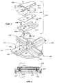
- a polishing pad comprises a carrier 10 having major flat surfaces 12, 14 on opposite sides thereof.
- the one major surface 14 has a plurality of spaced abrasive strips 16 secured to it.
- Figure 4 illustrates one such strip.
- the strip is elongate in shape having an exposed convex upper surface 18 and a flat lower surface 20. Integrally formed with the lower surface 20 are three spaced pins 22.
- the polymer of the strip 16 will preferably be a thermoplastic polymer and the strip made by injection moulding. Any one of the thermoplastic polymers described above may be used.
- the abrasive particles will preferably be diamond.
- the strips 16 are secured to the surface 14 by locating each strip in a recess 24 and the pins in complemental holes 26 formed in the carrier 10.
- Each strip presents an upper convex polishing surface 18.
- the polishing surface 18 may also be flat.
- one of the side surfaces 19a and 19b may be convex and the other concave, rather than flat, as illustrated.
- the strips 16 may have a plurality of fine holes extending from surface 18 to surface 20 or a number of cut-outs formed in the surface 18.
- the strips 16 are arranged across the surface 14 such that they extend across the whole of this surface and are transverse and diagonal to the longitudinal edges 14a and 14b of that surface 14. This arrangement is a preferred arrangement because the polishing pad, in use, will be mounted on a polishing head for rotation about an axis transverse to the longitudinal edges 14a and 14b.
- the carrier 10 has spaced pins 28 integrally formed with the lower surface 12. These pins 28 are received by complemental holes 30 in a base 32, the base 32 being adapted to be mounted on a polishing head. The location of the pins 28 in the holes 30 detachably secures the carrier 10 to the base 32. The engagement of the pins 28 in the holes 30 is such that the carrier 10 will be firmly secured to the base 32 to enable polishing to take place. However, when the abrasive strips 16 have worn to a point where effective polishing is no longer possible, the carrier may be removed by inserting an instrument such as a screwdriver in recess 34 and prising the carrier off the base. A new carrier with abrasive strips can then be attached to the base 32.
- the polishing pad provides effective polishing which, it has been found, can achieve in excess of 1000 square metres of granite polishing for a three millimetre height of abrasive strip. Since both the strips and the carrier can, and preferably are, made by injection moulding, this can be achieved at a relatively low cost. When the pad is consumed, it can be replaced quickly and easily by a new pad.
- the base 32 may be made of metal or a polymer such as acetal polymer.
- the distance between the polishing surface 18 of each strip and the surface 14 of the carrier will generally be up to 5mm, and typically 1 to 3mm.
- Figure 5 shows the rotary polishing head 40 of a known polishing apparatus used to polish the surface of a material such as granite or marble.
- the polishing head 40 has an off-centre hub 42 and four arms 44 radiating from the hub.
- Each arm 44 includes an elongate support member 46 which is formed with a longitudinal recess 48 of dovetail section.
- Figure 5 also shows four polishing pad assemblies 50, one for each arm 44.
- Each assembly 50 has four main components, namely a base 52, an intermediate pad 54, an insert 56 and a polishing pad 58.
- the base 52 in each case is made of metal or polymer and has a longitudinally extending locating portion 60 which is of dovetail section and which is dimensioned to slide radially into the recess 48 of one of the support members 46. Screws 62 passing downwardly through the base 52 serve to adjust the base in position on the support member 46 such that the abrasive layer 76 is parallel to a surface which is to be polished.
- Each base 52 is formed with a longitudinally extending recess 64 which tapers down in width in a radially inward direction. The sides of the recess 64 are slightly undercut. In addition, each base is formed with screw holes 66 countersunk from below as illustrated in Figure 7.
- the intermediate pads 54 are made of a material such as natural or synthetic rubber and are resilient. They have a tapering shape and are located in the recesses 64.
- the inserts 56 are made of metal or polymer and each has a slightly tapering shape in cross-section. Each insert is formed with threaded holes 70 which align with the screw holes 66, and with corresponding holes in the pad 54, when the insert is slipped radially to the appropriate position in the relevant recess 64. Cap screws 72 are located in the aligned holes to secure the insert to the base.
- spacers 68 are provided in each hole 66.
- the spacers 68 limit the amount by which the insert 56 can be drawn towards the base, and hence the compressive force that is applied to the pad 54 when the screws 72 are fully tightened.
- Each polishing pad 58 has a steel carrier 74 and an abrasive layer 76.
- the carrier 74 has side flanges 78 and a central section 80 which is slightly arcuate in transverse cross-section.
- the abrasive layer 76 extends only over the central section 80 and has a convex upper polishing surface.
- the flanges 78 are formed with longitudinally spaced holes 82.
- the abrasive pad 58 is of tapering shape and the side flanges 78 of the carrier are correspondingly convergent in a direction towards the narrower end of the pad.
- the pads 58 are located over the inserts 56 with the inserts embraced between the flanges 78, and are secured to the inserts by cap screws 84 which pass through the holes 82 and into corresponding, threaded holes formed in the inserts.
- the polishing head 40 is rotated and the polishing pad assemblies describe a pendular path.
- the polishing surfaces presented by the abrasive layers 76 of the polishing pads 58 are applied with appropriate axial pressure to a surface such as a surface of a block of granite. These polishing surfaces apply a polishing action to the relevant surface.
- compositions for the abrasive layer all using diamond as the abrasive, have been tried and found to be successful.
- examples of these compositions are: Polymer Diamond Concentration Vol.% Diamond Size (Microns) PEEK 16 53 - 63 PEEK 12 190 PEEK 10 115 PEEK 8 90 PEEK 6 60 PEEK 4 20 PEEK 1 5
Claims (15)
- Polierunterlage, umfassend einen Träger (10) mit Hauptoberflächen (12, 14) an seinen gegenüberliegenden Seiten, wobei die Hauptoberflächen Längskanten (14a, 14b) und eine an einer dieser Oberflächen befestigte Schleifmittelschicht aufweisen, wobei die Schleifmittelschicht eine Vielzahl von mit Abstand voneinander angeordneten Streifen (16) aufweist, die an der Oberfläche (14) befestigt sind, so daß sie quer zu den Längskanten (14a, 14b) auf der Oberfläche (14) liegen, und Hauptflächen der Streifen freigelegt sind, so daß sie Schleifmittel-Polieroberflächen (18) darstellen, und wobei die Schleifmittelschicht weiter ein nichtporöses thermoplastisches Polymer umfaßt, das eine Masse aus einzelnen Schleifmittelteilchen darin gleichmäßig dispergiert umfaßt, wobei die Schleifmittelteilchen eine Teilchengröße von bis zu 500 Mikrometern aufweisen und in der Schicht in einer Konzentration von bis zu 30 Vol.-% vorhanden sind.
- Polierunterlage nach Anspruch 1, wobei die Streifen (16) an der Hauptoberfläche (14) befestigt sind, so daß sie diagonal zu den Längskanten (14a, 14b) dieser Oberfläche (14) liegen.
- Polierunterlage nach Anspruch 1 oder Anspruch 2, wobei die Streifen (16) Strukturen (22) haben, die in komplementäre Strukturen (26) in oder auf der Trägeroberfläche (14) eingreifen, so daß die Streifen (16) an der Trägeroberfläche (14) befestigt werden.
- Polierunterlage nach Anspruch 3, wobei die komplementären Strukturen Stifte (22) und Löcher (26) sind.
- Polierunterlage nach einem der Ansprüche 1 bis 4, wobei die Streifen (16) gleichmäßig auf der Trägeroberfläche (14), an der sie befestigt sind, in Zwischenräumen angeordnet sind.
- Polierunterlage nach einem der Ansprüche 1 bis 5, wobei die Streifen (16) bis zu 70 % der Trägeroberfläche (14), an der sie befestigt sind, bedecken.
- Polierunterlage nach einem der Ansprüche 1 bis 6, wobei die Polieroberfläche (18) jedes Streifens konvex ist.
- Polierunterlage nach einem der vorhergehenden Ansprüche, wobei der Träger (10) abnehmbar an einem Grundkörper (32) befestigt ist, der zur Anbringung an einen Polierkopf angepaßt ist.
- Polierunterlage nach Anspruch 8, wobei der Träger (10) abnehmbar durch eingreifende Strukturen (28) auf oder in der Oberfläche eines Trägers (10) an der Oberfläche eines Grundkörpers (32) mit komplementären Strukturen (30) auf oder in der Oberfläche des Grundkörpers befestigt ist.
- Polierunterlage nach Anspruch 9, wobei die komplementären Strukturen Stifte (28) und Löcher (30) sind.
- Polierunterlage nach einem der vorhergehenden Ansprüche, wobei die Teilchengröße der Schleifmittelteilchen im Bereich von 2 bis 300 Mikrometer liegt.
- Polierunterlage nach einem der vorhergehenden Ansprüche, wobei die Konzentration von Schleifmittelteilchen in der Schleifmittelschicht (16) im Bereich von 1 bis 12 Vol.-% liegt.
- Polierunterlage nach einem der vorhergehenden Ansprüche, wobei die Schleifmittelteilchen aus Diamant und kubischem Bornitrid ausgewählt sind.
- Polierunterlage nach einem der vorhergehenden Ansprüche, wobei das thermoplastische Polymer aus Polyetheretherketon, Polyetherketon, Polyaryletherketon, Poly(amid-imid), Polyphenylensulfid und Flüssigkristall-Polymer ausgewählt ist.
- Verwendung einer Polierunterlage nach einem der Ansprüche 1 bis 14 für das Fein-Oberflächenbehandeln oder Polieren von Werkstücken aus Stein oder Keramik.
Applications Claiming Priority (4)
| Application Number | Priority Date | Filing Date | Title |
|---|---|---|---|
| GB929205664A GB9205664D0 (en) | 1992-03-16 | 1992-03-16 | Polishing pad |
| GB9205664 | 1992-03-16 | ||
| GB929221397A GB9221397D0 (en) | 1992-10-12 | 1992-10-12 | Polishing pad |
| GB9221397 | 1992-10-12 |
Publications (2)
| Publication Number | Publication Date |
|---|---|
| EP0561610A1 EP0561610A1 (de) | 1993-09-22 |
| EP0561610B1 true EP0561610B1 (de) | 1996-01-10 |
Family
ID=26300538
Family Applications (1)
| Application Number | Title | Priority Date | Filing Date |
|---|---|---|---|
| EP93301976A Expired - Lifetime EP0561610B1 (de) | 1992-03-16 | 1993-03-16 | Polierscheibe |
Country Status (9)
| Country | Link |
|---|---|
| US (1) | US5567503A (de) |
| EP (1) | EP0561610B1 (de) |
| JP (1) | JPH06134675A (de) |
| AT (1) | ATE132788T1 (de) |
| AU (1) | AU654901B2 (de) |
| CA (1) | CA2091660A1 (de) |
| DE (1) | DE69301259T2 (de) |
| ES (1) | ES2082592T3 (de) |
| TW (1) | TW243466B (de) |
Cited By (1)
| Publication number | Priority date | Publication date | Assignee | Title |
|---|---|---|---|---|
| CN108081132A (zh) * | 2017-12-15 | 2018-05-29 | 广东五月花网络科技有限公司 | 一种大理石抛光块的固定结构 |
Families Citing this family (86)
| Publication number | Priority date | Publication date | Assignee | Title |
|---|---|---|---|---|
| IT1266157B1 (it) * | 1994-07-08 | 1996-12-23 | Veglio Hs Srl | Inserto di supporto per montare in modo elastico un elemento abrasivo per l'uso su macchine calibratrici a teste rotanti con bracci |
| US6876454B1 (en) | 1995-03-28 | 2005-04-05 | Applied Materials, Inc. | Apparatus and method for in-situ endpoint detection for chemical mechanical polishing operations |
| DE69618698T2 (de) | 1995-03-28 | 2002-08-14 | Applied Materials Inc | Verfahren und Vorrichtung zur In-Situ-Kontroll und Bestimmung des Endes von chemisch-mechanischen Planiervorgänge |
| US5893796A (en) * | 1995-03-28 | 1999-04-13 | Applied Materials, Inc. | Forming a transparent window in a polishing pad for a chemical mechanical polishing apparatus |
| US5709589A (en) * | 1996-03-29 | 1998-01-20 | Boone; Charles Daniel | Hardwood floor finishing process |
| KR100210840B1 (ko) * | 1996-12-24 | 1999-07-15 | 구본준 | 기계 화학적 연마 방법 및 그 장치 |
| US5762545A (en) * | 1997-02-07 | 1998-06-09 | Edwards; Kerri O. | Sanding disk with extended blades |
| US6196911B1 (en) * | 1997-12-04 | 2001-03-06 | 3M Innovative Properties Company | Tools with abrasive segments |
| US6284345B1 (en) * | 1997-12-08 | 2001-09-04 | Washington University | Designer particles of micron and submicron dimension |
| JP3295888B2 (ja) * | 1998-04-22 | 2002-06-24 | 株式会社藤森技術研究所 | ケミカルマシンポリッシャの研磨盤用研磨ドレッサ |
| WO2000030812A1 (en) * | 1998-11-25 | 2000-06-02 | Repla S.R.L. | Abrasive tool for smoothing machines |
| KR100585480B1 (ko) | 1999-01-21 | 2006-06-02 | 롬 앤드 하스 일렉트로닉 머티리얼스 씨엠피 홀딩스 인코포레이티드 | 개선된 연마 패드 및 기판의 연마 방법 |
| US20020016139A1 (en) * | 2000-07-25 | 2002-02-07 | Kazuto Hirokawa | Polishing tool and manufacturing method therefor |
| GB0025745D0 (en) * | 2000-10-20 | 2000-12-06 | H K Founders Ltd | Semiconductor wafer manufacturing equipment |
| CN1224499C (zh) * | 2000-12-01 | 2005-10-26 | 东洋橡膠工业株式会社 | 研磨垫及其制造方法和研磨垫用缓冲层 |
| US6672943B2 (en) * | 2001-01-26 | 2004-01-06 | Wafer Solutions, Inc. | Eccentric abrasive wheel for wafer processing |
| US6632012B2 (en) | 2001-03-30 | 2003-10-14 | Wafer Solutions, Inc. | Mixing manifold for multiple inlet chemistry fluids |
| US6641472B2 (en) * | 2001-04-27 | 2003-11-04 | Ciena Corporation | Polishing pad assembly for fiber optic cable connector polishing apparatus |
| US7175514B2 (en) | 2001-04-27 | 2007-02-13 | Ciena Corporation | Polishing fixture assembly for a fiber optic cable connector polishing apparatus |
| ITPC20010018U1 (it) * | 2001-08-06 | 2003-02-06 | Tullio Arcobello | Utensile, in particolare settore diamantato per macchine e per la lucidatura di superfici quali agglomerati, piastrelle o simili. |
| US6612459B2 (en) * | 2001-09-04 | 2003-09-02 | Todd Young | Nestable multiple compartment tray for faux painting material and applicators |
| DE20116110U1 (de) * | 2001-10-01 | 2001-12-06 | Arminius Gmbh Schleifmittel | Rotationsschleifwerkzeug |
| TW561541B (en) * | 2001-10-09 | 2003-11-11 | Hitachi Chemical Co Ltd | Polishing pad for CMP, method for polishing substrate using it and method for producing polishing pad for CMP |
| US20050009456A1 (en) * | 2001-11-01 | 2005-01-13 | Tatsuya Sasaki | Polishing apparatus |
| US6739963B1 (en) * | 2002-12-20 | 2004-05-25 | Promociones Crevimas, S.L. | Disk for grinding concrete |
| JP2006520273A (ja) * | 2003-03-14 | 2006-09-07 | 株式会社荏原製作所 | 研磨工具および研磨装置 |
| US7001827B2 (en) * | 2003-04-15 | 2006-02-21 | International Business Machines Corporation | Semiconductor wafer front side protection |
| US7094140B2 (en) * | 2003-06-03 | 2006-08-22 | Onfloor Technologies, L.L.C. | Abrasive sanding surface |
| SE525501C2 (sv) * | 2003-06-11 | 2005-03-01 | Htc Sweden Ab | Slipplatta samt en slipelementbärande hållarplatta för lösbar montering på en slipplatta |
| US7481602B2 (en) * | 2004-08-16 | 2009-01-27 | Lampley Leonard A | Diamond trowel blade |
| US7255513B2 (en) * | 2004-08-16 | 2007-08-14 | Lampley Leonard A | Diamond trowel blade |
| KR100492854B1 (ko) * | 2004-09-15 | 2005-06-02 | 세원테크 주식회사 | 연마 휠 |
| US20060116060A1 (en) * | 2004-11-29 | 2006-06-01 | Htc Sweden Ab | Holder plate supporting grinding elements |
| US20070224925A1 (en) * | 2006-03-21 | 2007-09-27 | Rajeev Bajaj | Chemical Mechanical Polishing Pad |
| US20090277098A1 (en) * | 2004-12-06 | 2009-11-12 | Klaus-Peter Spies | Abrasive and Method of Fabricating Same |
| SE530209C2 (sv) * | 2005-01-07 | 2008-04-01 | Htc Sweden Ab | Bearbetningsplatta med bearbetningselement med separat foder |
| US7744447B2 (en) * | 2005-03-16 | 2010-06-29 | Goei, Co., Ltd. | Abrasive disc |
| CN100465713C (zh) * | 2005-06-20 | 2009-03-04 | 乐金显示有限公司 | 液晶显示设备用研磨机轮和用其制造液晶显示设备的方法 |
| CH699037B1 (de) * | 2005-12-21 | 2010-01-15 | Ilgner Schleif Innovationen Gmbh | Schleifwerkzeug für Naturstein-, Kunststein- und Industrieböden. |
| US7192339B1 (en) * | 2006-01-19 | 2007-03-20 | Equipment Development Company, Inc. | Grinder disc, insert holder and insert assembly |
| US7147548B1 (en) | 2006-04-03 | 2006-12-12 | Mohsen Mehrabi | Grinding and cutting head |
| US7775741B2 (en) * | 2006-05-26 | 2010-08-17 | Paul Copoulos | Apparatus and method for surface finishing cured concrete |
| US7530762B2 (en) * | 2006-05-26 | 2009-05-12 | Johnny Reed | Methods and apparatuses for surface finishing cured concrete |
| US7419422B1 (en) | 2006-10-09 | 2008-09-02 | Mohsen Mehrabi | Rotary cutting head |
| US20080176498A1 (en) * | 2007-01-18 | 2008-07-24 | Nufinish Corporation | Grinding tools and apparatus for securing grinding tools to grinding machines |
| US7713109B2 (en) * | 2007-01-19 | 2010-05-11 | Michael Jack Estes | Quick-change grinding pad and mounting system |
| EP1955809A1 (de) * | 2007-02-12 | 2008-08-13 | HTC Sweden AB | Werkzeug zum Bearbeiten von Stein- oder Betonböden |
| US7997960B2 (en) * | 2007-09-13 | 2011-08-16 | Williams Sr Bruce Michael | Floor resurfacing disk |
| SE533586C2 (sv) * | 2008-09-05 | 2010-11-02 | Husqvarna Ab | Dubbelradig abrasiv skiva |
| EP2454053B1 (de) | 2009-07-15 | 2013-09-25 | Blastrac B.V. | Schleifkopf für schleifmaschine |
| ES1071330Y (es) * | 2009-09-30 | 2010-05-12 | Matilla Botella Raquel | Pieza multicapa para el pulido de piedra |
| KR100987579B1 (ko) * | 2009-12-14 | 2010-10-12 | (주)성심 | 연마용 툴의 탈부착이 용이한 연마 휠 어셈블리 |
| JP5686338B2 (ja) * | 2009-12-22 | 2015-03-18 | 日鉄住金防蝕株式会社 | 回転研削工具およびその製造方法 |
| US8192255B2 (en) * | 2010-02-11 | 2012-06-05 | Eric Gallup | Tool holder with tapered slot for a grinding machine |
| US9387569B2 (en) * | 2013-04-27 | 2016-07-12 | John Blick | Leather head finishing system having plurality of apertures and angled shoe rails |
| USD746654S1 (en) | 2013-12-16 | 2016-01-05 | Husqvarna Ab | Cutting disk |
| KR101602553B1 (ko) * | 2014-03-11 | 2016-03-10 | 김용권 | 연마장치 |
| USD795666S1 (en) | 2014-06-06 | 2017-08-29 | Diamond Tool Supply, Inc. | Polishing pad |
| WO2017053737A1 (en) | 2015-09-24 | 2017-03-30 | Diamond Tool Supply, Inc. | Polishing or grinding pad assembly |
| US10414012B2 (en) * | 2017-01-13 | 2019-09-17 | Husqvarna Construction Products North America, Inc. | Grinding pad apparatus |
| US10246885B2 (en) | 2014-09-18 | 2019-04-02 | Husqvarna Construction Products North America, Inc. | Grouting pan assembly with reinforcement ring |
| US9580916B2 (en) | 2014-09-18 | 2017-02-28 | Diamond Tool Supply, Inc. | Method for finishing a composite surface and a grounting pan for finishing a composite surface |
| KR101556565B1 (ko) * | 2015-02-02 | 2015-10-02 | 이화다이아몬드공업 주식회사 | 그라인딩 공구 |
| TWI609742B (zh) * | 2015-04-20 | 2018-01-01 | 中國砂輪企業股份有限公司 | 研磨工具 |
| TWI603813B (zh) * | 2015-04-20 | 2017-11-01 | 中國砂輪企業股份有限公司 | 研磨工具及其製造方法 |
| CN105234846A (zh) * | 2015-09-16 | 2016-01-13 | 丹阳市长平机械有限公司 | 一种分体式磨轮 |
| US20170291272A1 (en) * | 2016-04-11 | 2017-10-12 | Diamond Productions Ltd. | Cylindrical abrasive for floor finishing machine |
| US11697182B2 (en) | 2016-04-27 | 2023-07-11 | Dynamic Concrete, Llc | Method and apparatus for removing stock material from a surface |
| US10259095B2 (en) | 2016-04-27 | 2019-04-16 | Ron Yagur | Method and apparatus for treating a floor surface with zero-tolerance edging |
| USD854902S1 (en) | 2016-09-23 | 2019-07-30 | Husqvarna Construction Products North America, Inc. | Polishing or grinding pad |
| IT201700060693A1 (it) * | 2017-06-01 | 2018-12-01 | Ditech S R L | Composizione abrasiva per la lucidatura di manufatti ceramici e/o pietre naturali e relativo procedimento di fabbricazione |
| USD958626S1 (en) | 2017-08-30 | 2022-07-26 | Husqvarna Ab | Polishing or grinding pad assembly with abrasive disks, reinforcement and pad |
| AU201810919S (en) | 2017-08-30 | 2018-04-13 | Husqvarna Construction Products North America | Polishing or grinding pad assembly with abrasive discs reinforcement and pad |
| USD927952S1 (en) | 2017-08-30 | 2021-08-17 | Husqvarna Ab | Polishing or grinding pad assembly with abrasive disk, spacer, reinforcement and pad |
| US11396085B2 (en) * | 2017-09-15 | 2022-07-26 | Diamond Productions Ltd. | Adapter for coupling abrasive elements to a floor finishing machine |
| US10710214B2 (en) * | 2018-01-11 | 2020-07-14 | Husqvarna Ab | Polishing or grinding pad with multilayer reinforcement |
| US10926375B2 (en) | 2018-06-20 | 2021-02-23 | Gestion Anny Picard Inc. | Pressure-fit grinding pad assembly and method of construction |
| USD876501S1 (en) * | 2018-10-05 | 2020-02-25 | Diamond Productions Ltd. | Polishing machine attachment for grinding and polishing concrete |
| US20220364375A1 (en) * | 2019-09-23 | 2022-11-17 | Concria Oy | Tool for the mechanical treatment of a concrete floor |
| US11942319B2 (en) * | 2020-12-18 | 2024-03-26 | Applied Materials, Inc. | Pad carrier for horizontal pre-clean module |
| WO2022182817A1 (en) | 2021-02-24 | 2022-09-01 | Milwaukee Electric Tool Corporation | Concrete trowel |
| WO2022182820A1 (en) * | 2021-02-24 | 2022-09-01 | Milwaukee Electric Tool Corporation | Concrete trowel |
| SE544763C2 (en) * | 2021-03-03 | 2022-11-08 | Husqvarna Ab | Abrasive tools for grinding and polishing concrete surfaces |
| US20220331927A1 (en) * | 2021-04-16 | 2022-10-20 | SlurryMonster, LLC | Detachable grinding tool |
| IT202100013040A1 (it) * | 2021-05-20 | 2022-11-20 | Abra Iride S P A | Utensile abrasivo per la lavorazione superficiale di pietre naturali, agglomerati con resine sintetiche o con leganti idraulici e materiali ceramici. |
| IT202100013031A1 (it) * | 2021-05-20 | 2022-11-20 | Abra Iride S P A | Utensile abrasivo per la lavorazione superficiale di pietre naturali, agglomerati con resine sintetiche o con leganti idraulici e materiali ceramici. |
Family Cites Families (24)
| Publication number | Priority date | Publication date | Assignee | Title |
|---|---|---|---|---|
| US1988065A (en) * | 1931-09-26 | 1935-01-15 | Carborundum Co | Manufacture of open-spaced abrasive fabrics |
| US2059583A (en) * | 1934-05-21 | 1936-11-03 | Carborundum Co | Abrasive belt |
| US2115904A (en) * | 1934-10-04 | 1938-05-03 | Carborundum Co | Curved abrasive fabric |
| US2806772A (en) * | 1954-09-15 | 1957-09-17 | Electro Refractories & Abrasiv | Abrasive bodies |
| US2806882A (en) * | 1954-09-16 | 1957-09-17 | Hoffmann La Roche | Acyclic ketone |
| FR1390205A (fr) * | 1963-06-04 | 1965-02-26 | Zane & C Snc | Disque abrasif flexible, procédé pour sa fabrication et moyens pour réaliser ce procédé |
| US3383191A (en) * | 1965-06-03 | 1968-05-14 | Simonds Abrasive Company | Diamond abrasive article containing hexagonal crystalline boron nitride particles |
| US3594963A (en) * | 1969-07-17 | 1971-07-27 | Univis Inc | Grinding pad |
| US3795078A (en) * | 1972-11-01 | 1974-03-05 | Norton Co | Segmental cut-off wheel |
| US3960518A (en) * | 1973-07-19 | 1976-06-01 | Hall George H | Method of forming a cutting tool |
| NL162006C (nl) * | 1973-09-26 | Norddeutsche Schleifmittel Ind | Slijpwerktuig. | |
| US4369046A (en) * | 1979-06-15 | 1983-01-18 | Abrasives International N.V. | Process for making an abrasive grinding wheel |
| IN155783B (de) * | 1980-04-02 | 1985-03-09 | De Beers Ind Diamond | |
| FR2532875A1 (fr) * | 1982-09-14 | 1984-03-16 | Sti Applic Indles Diamant | Meule a patins abrasifs multiples |
| JPS5993264A (ja) * | 1982-11-19 | 1984-05-29 | Tokyo Daiyamondo Kogu Seisakusho:Kk | レジンボンド超砥粒研削砥石 |
| JPS60167770A (ja) * | 1984-02-09 | 1985-08-31 | Okayama Ishiku Center:Kk | ブレ−ドにおけるチツプの装着構造 |
| US4927432A (en) * | 1986-03-25 | 1990-05-22 | Rodel, Inc. | Pad material for grinding, lapping and polishing |
| US4787362A (en) * | 1986-10-20 | 1988-11-29 | Thermocarbon, Inc. | Abrasive blade having a polycrystalline ceramic core |
| US5049165B1 (en) * | 1989-01-30 | 1995-09-26 | Ultimate Abrasive Syst Inc | Composite material |
| IT1230092B (it) * | 1989-04-27 | 1991-10-05 | Vincent Spa | Utensile per teste operatrici di macchine levigatrici di materiali lapidei o simili. |
| JPH0783725B2 (ja) * | 1989-09-28 | 1995-09-13 | 帝人株式会社 | シート状ブラシ材料及びブラシ構造物 |
| GB9020462D0 (en) * | 1990-09-19 | 1990-10-31 | Filters For Industry Ltd | Abrasive segments |
| US5197249A (en) * | 1991-02-07 | 1993-03-30 | Wiand Ronald C | Diamond tool with non-abrasive segments |
| US5243790A (en) * | 1992-06-25 | 1993-09-14 | Abrasifs Vega, Inc. | Abrasive member |
-
1993
- 1993-03-12 AU AU35200/93A patent/AU654901B2/en not_active Ceased
- 1993-03-15 CA CA002091660A patent/CA2091660A1/en not_active Abandoned
- 1993-03-16 JP JP5094795A patent/JPH06134675A/ja active Pending
- 1993-03-16 ES ES93301976T patent/ES2082592T3/es not_active Expired - Lifetime
- 1993-03-16 EP EP93301976A patent/EP0561610B1/de not_active Expired - Lifetime
- 1993-03-16 AT AT93301976T patent/ATE132788T1/de active
- 1993-03-16 DE DE69301259T patent/DE69301259T2/de not_active Expired - Fee Related
- 1993-03-25 TW TW082102242A patent/TW243466B/zh active
-
1994
- 1994-09-19 US US08/308,399 patent/US5567503A/en not_active Expired - Fee Related
Cited By (1)
| Publication number | Priority date | Publication date | Assignee | Title |
|---|---|---|---|---|
| CN108081132A (zh) * | 2017-12-15 | 2018-05-29 | 广东五月花网络科技有限公司 | 一种大理石抛光块的固定结构 |
Also Published As
| Publication number | Publication date |
|---|---|
| AU654901B2 (en) | 1994-11-24 |
| AU3520093A (en) | 1993-09-23 |
| TW243466B (de) | 1995-03-21 |
| DE69301259D1 (de) | 1996-02-22 |
| ATE132788T1 (de) | 1996-01-15 |
| CA2091660A1 (en) | 1993-09-17 |
| US5567503A (en) | 1996-10-22 |
| JPH06134675A (ja) | 1994-05-17 |
| ES2082592T3 (es) | 1996-03-16 |
| DE69301259T2 (de) | 1996-09-19 |
| EP0561610A1 (de) | 1993-09-22 |
Similar Documents
| Publication | Publication Date | Title |
|---|---|---|
| EP0561610B1 (de) | Polierscheibe | |
| US5454752A (en) | Abrasive device | |
| EP0550487B1 (de) | Schleifsegment | |
| EP0655024B1 (de) | Schleifwerkzeug-bestandteil | |
| US3867795A (en) | Composite resinoid bonded abrasive wheels | |
| KR100523304B1 (ko) | 연마 세그먼트를 갖춘 공구 | |
| US8795034B2 (en) | Brazed diamond dressing tool | |
| KR100794823B1 (ko) | 윈도우를 갖는 폴리싱 패드 | |
| KR20010042180A (ko) | 연삭 공구 | |
| KR20040062681A (ko) | 도전성 재료의 연마 및 증착용 연삭물 | |
| CA2375956A1 (en) | Abrasive tools for grinding electronic components | |
| CA1273802A (en) | Grinding wheel | |
| US6949012B2 (en) | Polishing pad conditioning method and apparatus | |
| WO2007022016A2 (en) | Abrasive tool | |
| US4907376A (en) | Plate mounted grinding wheel | |
| US20040038633A1 (en) | Sanding system | |
| US20060068691A1 (en) | Abrading tools with individually controllable grit and method of making the same | |
| JPS62188675A (ja) | 超砥粒切断研削研磨工具要素 | |
| JPS63283866A (ja) | 超砥粒切断・研削砥石 | |
| JPH11138449A (ja) | 平面研削盤用砥石・ホルダ組立体及び砥石セグメント | |
| JPH1142566A (ja) | 研削治具 | |
| TW586988B (en) | Retaining ring for chemical-mechanical polishing | |
| JP2003080443A (ja) | 研磨用砥石及び研磨工具 | |
| HU214734B (hu) | Gyémántlapkás marófej kőmegmunkáláshoz | |
| PL145286B2 (en) | Grinding tool for making shallow indentations in surfaces |
Legal Events
| Date | Code | Title | Description |
|---|---|---|---|
| PUAI | Public reference made under article 153(3) epc to a published international application that has entered the european phase |
Free format text: ORIGINAL CODE: 0009012 |
|
| AK | Designated contracting states |
Kind code of ref document: A1 Designated state(s): AT BE CH DE ES FR GB IE IT LI NL SE |
|
| 17P | Request for examination filed |
Effective date: 19930824 |
|
| 17Q | First examination report despatched |
Effective date: 19940603 |
|
| GRAA | (expected) grant |
Free format text: ORIGINAL CODE: 0009210 |
|
| AK | Designated contracting states |
Kind code of ref document: B1 Designated state(s): AT BE CH DE ES FR GB IE IT LI NL SE |
|
| REF | Corresponds to: |
Ref document number: 132788 Country of ref document: AT Date of ref document: 19960115 Kind code of ref document: T |
|
| ITF | It: translation for a ep patent filed |
Owner name: BARZANO' E ZANARDO MILANO S.P.A. |
|
| REG | Reference to a national code |
Ref country code: IE Ref legal event code: FG4D Free format text: 66859 |
|
| REF | Corresponds to: |
Ref document number: 69301259 Country of ref document: DE Date of ref document: 19960222 |
|
| REG | Reference to a national code |
Ref country code: CH Ref legal event code: NV Representative=s name: BOVARD AG PATENTANWAELTE |
|
| REG | Reference to a national code |
Ref country code: ES Ref legal event code: FG2A Ref document number: 2082592 Country of ref document: ES Kind code of ref document: T3 |
|
| ET | Fr: translation filed | ||
| PLBE | No opposition filed within time limit |
Free format text: ORIGINAL CODE: 0009261 |
|
| STAA | Information on the status of an ep patent application or granted ep patent |
Free format text: STATUS: NO OPPOSITION FILED WITHIN TIME LIMIT |
|
| 26N | No opposition filed | ||
| PGFP | Annual fee paid to national office [announced via postgrant information from national office to epo] |
Ref country code: CH Payment date: 19970320 Year of fee payment: 5 |
|
| PGFP | Annual fee paid to national office [announced via postgrant information from national office to epo] |
Ref country code: NL Payment date: 19970327 Year of fee payment: 5 |
|
| PG25 | Lapsed in a contracting state [announced via postgrant information from national office to epo] |
Ref country code: LI Free format text: LAPSE BECAUSE OF NON-PAYMENT OF DUE FEES Effective date: 19980331 Ref country code: CH Free format text: LAPSE BECAUSE OF NON-PAYMENT OF DUE FEES Effective date: 19980331 |
|
| PG25 | Lapsed in a contracting state [announced via postgrant information from national office to epo] |
Ref country code: NL Free format text: LAPSE BECAUSE OF NON-PAYMENT OF DUE FEES Effective date: 19981001 |
|
| REG | Reference to a national code |
Ref country code: CH Ref legal event code: PL |
|
| NLV4 | Nl: lapsed or anulled due to non-payment of the annual fee |
Effective date: 19981001 |
|
| PGFP | Annual fee paid to national office [announced via postgrant information from national office to epo] |
Ref country code: SE Payment date: 20000307 Year of fee payment: 8 |
|
| PGFP | Annual fee paid to national office [announced via postgrant information from national office to epo] |
Ref country code: AT Payment date: 20000313 Year of fee payment: 8 |
|
| PGFP | Annual fee paid to national office [announced via postgrant information from national office to epo] |
Ref country code: ES Payment date: 20000322 Year of fee payment: 8 |
|
| PGFP | Annual fee paid to national office [announced via postgrant information from national office to epo] |
Ref country code: BE Payment date: 20000518 Year of fee payment: 8 |
|
| PG25 | Lapsed in a contracting state [announced via postgrant information from national office to epo] |
Ref country code: AT Free format text: LAPSE BECAUSE OF NON-PAYMENT OF DUE FEES Effective date: 20010316 |
|
| PG25 | Lapsed in a contracting state [announced via postgrant information from national office to epo] |
Ref country code: SE Free format text: LAPSE BECAUSE OF NON-PAYMENT OF DUE FEES Effective date: 20010317 Ref country code: ES Free format text: LAPSE BECAUSE OF NON-PAYMENT OF DUE FEES Effective date: 20010317 |
|
| PG25 | Lapsed in a contracting state [announced via postgrant information from national office to epo] |
Ref country code: BE Free format text: LAPSE BECAUSE OF NON-PAYMENT OF DUE FEES Effective date: 20010331 |
|
| BERE | Be: lapsed |
Owner name: DE BEERS INDUSTRIAL DIAMOND DIVISION (PROPRIETARY Effective date: 20010331 |
|
| EUG | Se: european patent has lapsed |
Ref document number: 93301976.2 |
|
| REG | Reference to a national code |
Ref country code: GB Ref legal event code: IF02 |
|
| REG | Reference to a national code |
Ref country code: ES Ref legal event code: FD2A Effective date: 20030203 |
|
| PGFP | Annual fee paid to national office [announced via postgrant information from national office to epo] |
Ref country code: FR Payment date: 20060308 Year of fee payment: 14 |
|
| PGFP | Annual fee paid to national office [announced via postgrant information from national office to epo] |
Ref country code: DE Payment date: 20060309 Year of fee payment: 14 |
|
| PGFP | Annual fee paid to national office [announced via postgrant information from national office to epo] |
Ref country code: IE Payment date: 20060313 Year of fee payment: 14 |
|
| PGFP | Annual fee paid to national office [announced via postgrant information from national office to epo] |
Ref country code: GB Payment date: 20060315 Year of fee payment: 14 |
|
| GBPC | Gb: european patent ceased through non-payment of renewal fee |
Effective date: 20070316 |
|
| REG | Reference to a national code |
Ref country code: IE Ref legal event code: MM4A |
|
| PGFP | Annual fee paid to national office [announced via postgrant information from national office to epo] |
Ref country code: IT Payment date: 20070626 Year of fee payment: 15 |
|
| REG | Reference to a national code |
Ref country code: FR Ref legal event code: ST Effective date: 20071130 |
|
| PG25 | Lapsed in a contracting state [announced via postgrant information from national office to epo] |
Ref country code: IE Free format text: LAPSE BECAUSE OF NON-PAYMENT OF DUE FEES Effective date: 20070316 Ref country code: DE Free format text: LAPSE BECAUSE OF NON-PAYMENT OF DUE FEES Effective date: 20071002 |
|
| PG25 | Lapsed in a contracting state [announced via postgrant information from national office to epo] |
Ref country code: GB Free format text: LAPSE BECAUSE OF NON-PAYMENT OF DUE FEES Effective date: 20070316 |
|
| PG25 | Lapsed in a contracting state [announced via postgrant information from national office to epo] |
Ref country code: FR Free format text: LAPSE BECAUSE OF NON-PAYMENT OF DUE FEES Effective date: 20070402 |
|
| PG25 | Lapsed in a contracting state [announced via postgrant information from national office to epo] |
Ref country code: IT Free format text: LAPSE BECAUSE OF NON-PAYMENT OF DUE FEES Effective date: 20080316 |