EP0560157A1 - Festbettreaktoren mit kurzem Katalysatorbett in Strömungsrichtung - Google Patents
Festbettreaktoren mit kurzem Katalysatorbett in Strömungsrichtung Download PDFInfo
- Publication number
- EP0560157A1 EP0560157A1 EP93103212A EP93103212A EP0560157A1 EP 0560157 A1 EP0560157 A1 EP 0560157A1 EP 93103212 A EP93103212 A EP 93103212A EP 93103212 A EP93103212 A EP 93103212A EP 0560157 A1 EP0560157 A1 EP 0560157A1
- Authority
- EP
- European Patent Office
- Prior art keywords
- catalyst
- catalyst bed
- reactors
- flow
- reactor
- Prior art date
- Legal status (The legal status is an assumption and is not a legal conclusion. Google has not performed a legal analysis and makes no representation as to the accuracy of the status listed.)
- Granted
Links
- 239000003054 catalyst Substances 0.000 title claims abstract description 138
- 238000006243 chemical reaction Methods 0.000 claims abstract description 52
- 238000012546 transfer Methods 0.000 claims abstract description 29
- 239000000126 substance Substances 0.000 claims abstract description 18
- 239000007789 gas Substances 0.000 claims description 36
- 239000000463 material Substances 0.000 claims description 16
- 229910052751 metal Inorganic materials 0.000 claims description 7
- 239000002184 metal Substances 0.000 claims description 7
- 238000006356 dehydrogenation reaction Methods 0.000 claims description 6
- 238000005984 hydrogenation reaction Methods 0.000 claims description 6
- 230000015572 biosynthetic process Effects 0.000 claims description 4
- 238000010574 gas phase reaction Methods 0.000 claims description 3
- 238000000034 method Methods 0.000 claims description 3
- 230000029936 alkylation Effects 0.000 claims description 2
- 238000005804 alkylation reaction Methods 0.000 claims description 2
- 230000026030 halogenation Effects 0.000 claims description 2
- 238000005658 halogenation reaction Methods 0.000 claims description 2
- 230000003647 oxidation Effects 0.000 claims description 2
- 238000007254 oxidation reaction Methods 0.000 claims description 2
- 230000008569 process Effects 0.000 claims description 2
- 239000007858 starting material Substances 0.000 abstract description 17
- 239000011521 glass Substances 0.000 description 34
- 239000000047 product Substances 0.000 description 29
- LQNUZADURLCDLV-UHFFFAOYSA-N nitrobenzene Chemical compound [O-][N+](=O)C1=CC=CC=C1 LQNUZADURLCDLV-UHFFFAOYSA-N 0.000 description 24
- 239000000203 mixture Substances 0.000 description 16
- DMBHHRLKUKUOEG-UHFFFAOYSA-N diphenylamine Chemical compound C=1C=CC=CC=1NC1=CC=CC=C1 DMBHHRLKUKUOEG-UHFFFAOYSA-N 0.000 description 12
- 238000010276 construction Methods 0.000 description 11
- 238000009826 distribution Methods 0.000 description 11
- 239000001257 hydrogen Substances 0.000 description 11
- 229910052739 hydrogen Inorganic materials 0.000 description 11
- KDLHZDBZIXYQEI-UHFFFAOYSA-N palladium Substances [Pd] KDLHZDBZIXYQEI-UHFFFAOYSA-N 0.000 description 11
- PAYRUJLWNCNPSJ-UHFFFAOYSA-N Aniline Chemical compound NC1=CC=CC=C1 PAYRUJLWNCNPSJ-UHFFFAOYSA-N 0.000 description 10
- UFHFLCQGNIYNRP-UHFFFAOYSA-N Hydrogen Chemical compound [H][H] UFHFLCQGNIYNRP-UHFFFAOYSA-N 0.000 description 9
- HEMHJVSKTPXQMS-UHFFFAOYSA-M Sodium hydroxide Chemical compound [OH-].[Na+] HEMHJVSKTPXQMS-UHFFFAOYSA-M 0.000 description 9
- RPFGCUFAJAQNLJ-UHFFFAOYSA-N n-phenylcyclohexanimine Chemical compound C1CCCCC1=NC1=CC=CC=C1 RPFGCUFAJAQNLJ-UHFFFAOYSA-N 0.000 description 9
- IJGRMHOSHXDMSA-UHFFFAOYSA-N Atomic nitrogen Chemical compound N#N IJGRMHOSHXDMSA-UHFFFAOYSA-N 0.000 description 8
- 230000009849 deactivation Effects 0.000 description 8
- 238000013461 design Methods 0.000 description 7
- 238000001035 drying Methods 0.000 description 7
- XLYOFNOQVPJJNP-UHFFFAOYSA-N water Chemical compound O XLYOFNOQVPJJNP-UHFFFAOYSA-N 0.000 description 7
- 238000001816 cooling Methods 0.000 description 6
- 239000000243 solution Substances 0.000 description 6
- 230000008901 benefit Effects 0.000 description 5
- 230000000052 comparative effect Effects 0.000 description 4
- 230000002349 favourable effect Effects 0.000 description 4
- 229910052757 nitrogen Inorganic materials 0.000 description 4
- OKKJLVBELUTLKV-UHFFFAOYSA-N Methanol Chemical compound OC OKKJLVBELUTLKV-UHFFFAOYSA-N 0.000 description 3
- 230000004913 activation Effects 0.000 description 3
- 239000007864 aqueous solution Substances 0.000 description 3
- 230000000694 effects Effects 0.000 description 3
- 238000002474 experimental method Methods 0.000 description 3
- OGUCKKLSDGRKSH-UHFFFAOYSA-N oxalic acid oxovanadium Chemical compound [V].[O].C(C(=O)O)(=O)O OGUCKKLSDGRKSH-UHFFFAOYSA-N 0.000 description 3
- 229910052763 palladium Inorganic materials 0.000 description 3
- 239000002245 particle Substances 0.000 description 3
- 230000035515 penetration Effects 0.000 description 3
- 238000002360 preparation method Methods 0.000 description 3
- 239000000376 reactant Substances 0.000 description 3
- 238000007086 side reaction Methods 0.000 description 3
- ABKQFSYGIHQQLS-UHFFFAOYSA-J sodium tetrachloropalladate Chemical compound [Na+].[Na+].Cl[Pd+2](Cl)(Cl)Cl ABKQFSYGIHQQLS-UHFFFAOYSA-J 0.000 description 3
- HGINCPLSRVDWNT-UHFFFAOYSA-N Acrolein Chemical compound C=CC=O HGINCPLSRVDWNT-UHFFFAOYSA-N 0.000 description 2
- QGZKDVFQNNGYKY-UHFFFAOYSA-N Ammonia Chemical compound N QGZKDVFQNNGYKY-UHFFFAOYSA-N 0.000 description 2
- CTQNGGLPUBDAKN-UHFFFAOYSA-N O-Xylene Chemical group CC1=CC=CC=C1C CTQNGGLPUBDAKN-UHFFFAOYSA-N 0.000 description 2
- QQONPFPTGQHPMA-UHFFFAOYSA-N Propene Chemical compound CC=C QQONPFPTGQHPMA-UHFFFAOYSA-N 0.000 description 2
- LLEMOWNGBBNAJR-UHFFFAOYSA-N biphenyl-2-ol Chemical compound OC1=CC=CC=C1C1=CC=CC=C1 LLEMOWNGBBNAJR-UHFFFAOYSA-N 0.000 description 2
- 239000006227 byproduct Substances 0.000 description 2
- 239000012159 carrier gas Substances 0.000 description 2
- 230000003197 catalytic effect Effects 0.000 description 2
- 239000007795 chemical reaction product Substances 0.000 description 2
- 239000000571 coke Substances 0.000 description 2
- JHIVVAPYMSGYDF-UHFFFAOYSA-N cyclohexanone Chemical compound O=C1CCCCC1 JHIVVAPYMSGYDF-UHFFFAOYSA-N 0.000 description 2
- 238000010790 dilution Methods 0.000 description 2
- 239000012895 dilution Substances 0.000 description 2
- 239000012153 distilled water Substances 0.000 description 2
- 238000005516 engineering process Methods 0.000 description 2
- 230000017525 heat dissipation Effects 0.000 description 2
- 238000010438 heat treatment Methods 0.000 description 2
- 238000009434 installation Methods 0.000 description 2
- CPJRRXSHAYUTGL-UHFFFAOYSA-N isopentenyl alcohol Chemical compound CC(=C)CCO CPJRRXSHAYUTGL-UHFFFAOYSA-N 0.000 description 2
- 229940046892 lead acetate Drugs 0.000 description 2
- 239000007788 liquid Substances 0.000 description 2
- 238000011068 loading method Methods 0.000 description 2
- 238000004519 manufacturing process Methods 0.000 description 2
- 230000000750 progressive effect Effects 0.000 description 2
- 238000004064 recycling Methods 0.000 description 2
- 230000009467 reduction Effects 0.000 description 2
- 238000011144 upstream manufacturing Methods 0.000 description 2
- GPPXJZIENCGNKB-UHFFFAOYSA-N vanadium Chemical compound [V]#[V] GPPXJZIENCGNKB-UHFFFAOYSA-N 0.000 description 2
- 229910052720 vanadium Inorganic materials 0.000 description 2
- NWZSZGALRFJKBT-KNIFDHDWSA-N (2s)-2,6-diaminohexanoic acid;(2s)-2-hydroxybutanedioic acid Chemical compound OC(=O)[C@@H](O)CC(O)=O.NCCCC[C@H](N)C(O)=O NWZSZGALRFJKBT-KNIFDHDWSA-N 0.000 description 1
- SMZOUWXMTYCWNB-UHFFFAOYSA-N 2-(2-methoxy-5-methylphenyl)ethanamine Chemical compound COC1=CC=C(C)C=C1CCN SMZOUWXMTYCWNB-UHFFFAOYSA-N 0.000 description 1
- GVNVAWHJIKLAGL-UHFFFAOYSA-N 2-(cyclohexen-1-yl)cyclohexan-1-one Chemical compound O=C1CCCCC1C1=CCCCC1 GVNVAWHJIKLAGL-UHFFFAOYSA-N 0.000 description 1
- NIXOWILDQLNWCW-UHFFFAOYSA-N 2-Propenoic acid Natural products OC(=O)C=C NIXOWILDQLNWCW-UHFFFAOYSA-N 0.000 description 1
- SEPQTYODOKLVSB-UHFFFAOYSA-N 3-methylbut-2-enal Chemical compound CC(C)=CC=O SEPQTYODOKLVSB-UHFFFAOYSA-N 0.000 description 1
- PNEYBMLMFCGWSK-UHFFFAOYSA-N Alumina Chemical compound [O-2].[O-2].[O-2].[Al+3].[Al+3] PNEYBMLMFCGWSK-UHFFFAOYSA-N 0.000 description 1
- VEXZGXHMUGYJMC-UHFFFAOYSA-M Chloride anion Chemical compound [Cl-] VEXZGXHMUGYJMC-UHFFFAOYSA-M 0.000 description 1
- LFQSCWFLJHTTHZ-UHFFFAOYSA-N Ethanol Chemical compound CCO LFQSCWFLJHTTHZ-UHFFFAOYSA-N 0.000 description 1
- DGAQECJNVWCQMB-PUAWFVPOSA-M Ilexoside XXIX Chemical compound C[C@@H]1CC[C@@]2(CC[C@@]3(C(=CC[C@H]4[C@]3(CC[C@@H]5[C@@]4(CC[C@@H](C5(C)C)OS(=O)(=O)[O-])C)C)[C@@H]2[C@]1(C)O)C)C(=O)O[C@H]6[C@@H]([C@H]([C@@H]([C@H](O6)CO)O)O)O.[Na+] DGAQECJNVWCQMB-PUAWFVPOSA-M 0.000 description 1
- ISWSIDIOOBJBQZ-UHFFFAOYSA-N Phenol Chemical compound OC1=CC=CC=C1 ISWSIDIOOBJBQZ-UHFFFAOYSA-N 0.000 description 1
- LGRFSURHDFAFJT-UHFFFAOYSA-N Phthalic anhydride Natural products C1=CC=C2C(=O)OC(=O)C2=C1 LGRFSURHDFAFJT-UHFFFAOYSA-N 0.000 description 1
- 238000006887 Ullmann reaction Methods 0.000 description 1
- 230000004308 accommodation Effects 0.000 description 1
- 238000009825 accumulation Methods 0.000 description 1
- 239000011149 active material Substances 0.000 description 1
- 239000000654 additive Substances 0.000 description 1
- 229910021529 ammonia Inorganic materials 0.000 description 1
- JHIWVOJDXOSYLW-UHFFFAOYSA-N butyl 2,2-difluorocyclopropane-1-carboxylate Chemical compound CCCCOC(=O)C1CC1(F)F JHIWVOJDXOSYLW-UHFFFAOYSA-N 0.000 description 1
- 238000004364 calculation method Methods 0.000 description 1
- 238000003776 cleavage reaction Methods 0.000 description 1
- 150000001875 compounds Chemical class 0.000 description 1
- 238000010924 continuous production Methods 0.000 description 1
- 238000000354 decomposition reaction Methods 0.000 description 1
- 238000007865 diluting Methods 0.000 description 1
- 239000003085 diluting agent Substances 0.000 description 1
- 238000005429 filling process Methods 0.000 description 1
- 238000000227 grinding Methods 0.000 description 1
- IKDUDTNKRLTJSI-UHFFFAOYSA-N hydrazine monohydrate Substances O.NN IKDUDTNKRLTJSI-UHFFFAOYSA-N 0.000 description 1
- 229930195733 hydrocarbon Natural products 0.000 description 1
- 150000002430 hydrocarbons Chemical class 0.000 description 1
- 230000003993 interaction Effects 0.000 description 1
- 150000002500 ions Chemical class 0.000 description 1
- 230000014759 maintenance of location Effects 0.000 description 1
- FPYJFEHAWHCUMM-UHFFFAOYSA-N maleic anhydride Chemical compound O=C1OC(=O)C=C1 FPYJFEHAWHCUMM-UHFFFAOYSA-N 0.000 description 1
- 150000002739 metals Chemical class 0.000 description 1
- 230000004048 modification Effects 0.000 description 1
- 238000012986 modification Methods 0.000 description 1
- 238000000465 moulding Methods 0.000 description 1
- IJDNQMDRQITEOD-UHFFFAOYSA-N n-butane Chemical compound CCCC IJDNQMDRQITEOD-UHFFFAOYSA-N 0.000 description 1
- 229940078552 o-xylene Drugs 0.000 description 1
- 150000002894 organic compounds Chemical class 0.000 description 1
- 235000010292 orthophenyl phenol Nutrition 0.000 description 1
- 230000001590 oxidative effect Effects 0.000 description 1
- TWNQGVIAIRXVLR-UHFFFAOYSA-N oxo(oxoalumanyloxy)alumane Chemical compound O=[Al]O[Al]=O TWNQGVIAIRXVLR-UHFFFAOYSA-N 0.000 description 1
- 238000012856 packing Methods 0.000 description 1
- 150000002941 palladium compounds Chemical class 0.000 description 1
- 238000005192 partition Methods 0.000 description 1
- 239000002243 precursor Substances 0.000 description 1
- 238000005086 pumping Methods 0.000 description 1
- 239000011541 reaction mixture Substances 0.000 description 1
- 150000003839 salts Chemical class 0.000 description 1
- 238000004904 shortening Methods 0.000 description 1
- 229910052708 sodium Inorganic materials 0.000 description 1
- 239000011734 sodium Substances 0.000 description 1
- 239000002904 solvent Substances 0.000 description 1
- 238000006467 substitution reaction Methods 0.000 description 1
- 238000003786 synthesis reaction Methods 0.000 description 1
- 238000010626 work up procedure Methods 0.000 description 1
Images




Classifications
-
- C—CHEMISTRY; METALLURGY
- C07—ORGANIC CHEMISTRY
- C07C—ACYCLIC OR CARBOCYCLIC COMPOUNDS
- C07C45/00—Preparation of compounds having >C = O groups bound only to carbon or hydrogen atoms; Preparation of chelates of such compounds
- C07C45/27—Preparation of compounds having >C = O groups bound only to carbon or hydrogen atoms; Preparation of chelates of such compounds by oxidation
- C07C45/32—Preparation of compounds having >C = O groups bound only to carbon or hydrogen atoms; Preparation of chelates of such compounds by oxidation with molecular oxygen
- C07C45/33—Preparation of compounds having >C = O groups bound only to carbon or hydrogen atoms; Preparation of chelates of such compounds by oxidation with molecular oxygen of CHx-moieties
- C07C45/34—Preparation of compounds having >C = O groups bound only to carbon or hydrogen atoms; Preparation of chelates of such compounds by oxidation with molecular oxygen of CHx-moieties in unsaturated compounds
- C07C45/35—Preparation of compounds having >C = O groups bound only to carbon or hydrogen atoms; Preparation of chelates of such compounds by oxidation with molecular oxygen of CHx-moieties in unsaturated compounds in propene or isobutene
-
- B—PERFORMING OPERATIONS; TRANSPORTING
- B01—PHYSICAL OR CHEMICAL PROCESSES OR APPARATUS IN GENERAL
- B01J—CHEMICAL OR PHYSICAL PROCESSES, e.g. CATALYSIS OR COLLOID CHEMISTRY; THEIR RELEVANT APPARATUS
- B01J8/00—Chemical or physical processes in general, conducted in the presence of fluids and solid particles; Apparatus for such processes
- B01J8/02—Chemical or physical processes in general, conducted in the presence of fluids and solid particles; Apparatus for such processes with stationary particles, e.g. in fixed beds
- B01J8/0207—Chemical or physical processes in general, conducted in the presence of fluids and solid particles; Apparatus for such processes with stationary particles, e.g. in fixed beds the fluid flow within the bed being predominantly horizontal
-
- B—PERFORMING OPERATIONS; TRANSPORTING
- B01—PHYSICAL OR CHEMICAL PROCESSES OR APPARATUS IN GENERAL
- B01J—CHEMICAL OR PHYSICAL PROCESSES, e.g. CATALYSIS OR COLLOID CHEMISTRY; THEIR RELEVANT APPARATUS
- B01J8/00—Chemical or physical processes in general, conducted in the presence of fluids and solid particles; Apparatus for such processes
- B01J8/02—Chemical or physical processes in general, conducted in the presence of fluids and solid particles; Apparatus for such processes with stationary particles, e.g. in fixed beds
- B01J8/0207—Chemical or physical processes in general, conducted in the presence of fluids and solid particles; Apparatus for such processes with stationary particles, e.g. in fixed beds the fluid flow within the bed being predominantly horizontal
- B01J8/0235—Chemical or physical processes in general, conducted in the presence of fluids and solid particles; Apparatus for such processes with stationary particles, e.g. in fixed beds the fluid flow within the bed being predominantly horizontal in a spiral shaped bed
-
- B—PERFORMING OPERATIONS; TRANSPORTING
- B01—PHYSICAL OR CHEMICAL PROCESSES OR APPARATUS IN GENERAL
- B01J—CHEMICAL OR PHYSICAL PROCESSES, e.g. CATALYSIS OR COLLOID CHEMISTRY; THEIR RELEVANT APPARATUS
- B01J8/00—Chemical or physical processes in general, conducted in the presence of fluids and solid particles; Apparatus for such processes
- B01J8/02—Chemical or physical processes in general, conducted in the presence of fluids and solid particles; Apparatus for such processes with stationary particles, e.g. in fixed beds
- B01J8/0285—Heating or cooling the reactor
-
- B—PERFORMING OPERATIONS; TRANSPORTING
- B01—PHYSICAL OR CHEMICAL PROCESSES OR APPARATUS IN GENERAL
- B01J—CHEMICAL OR PHYSICAL PROCESSES, e.g. CATALYSIS OR COLLOID CHEMISTRY; THEIR RELEVANT APPARATUS
- B01J8/00—Chemical or physical processes in general, conducted in the presence of fluids and solid particles; Apparatus for such processes
- B01J8/02—Chemical or physical processes in general, conducted in the presence of fluids and solid particles; Apparatus for such processes with stationary particles, e.g. in fixed beds
- B01J8/06—Chemical or physical processes in general, conducted in the presence of fluids and solid particles; Apparatus for such processes with stationary particles, e.g. in fixed beds in tube reactors; the solid particles being arranged in tubes
- B01J8/067—Heating or cooling the reactor
-
- C—CHEMISTRY; METALLURGY
- C07—ORGANIC CHEMISTRY
- C07B—GENERAL METHODS OF ORGANIC CHEMISTRY; APPARATUS THEREFOR
- C07B39/00—Halogenation
-
- C—CHEMISTRY; METALLURGY
- C07—ORGANIC CHEMISTRY
- C07C—ACYCLIC OR CARBOCYCLIC COMPOUNDS
- C07C209/00—Preparation of compounds containing amino groups bound to a carbon skeleton
- C07C209/30—Preparation of compounds containing amino groups bound to a carbon skeleton by reduction of nitrogen-to-oxygen or nitrogen-to-nitrogen bonds
- C07C209/32—Preparation of compounds containing amino groups bound to a carbon skeleton by reduction of nitrogen-to-oxygen or nitrogen-to-nitrogen bonds by reduction of nitro groups
- C07C209/36—Preparation of compounds containing amino groups bound to a carbon skeleton by reduction of nitrogen-to-oxygen or nitrogen-to-nitrogen bonds by reduction of nitro groups by reduction of nitro groups bound to carbon atoms of six-membered aromatic rings in presence of hydrogen-containing gases and a catalyst
-
- C—CHEMISTRY; METALLURGY
- C07—ORGANIC CHEMISTRY
- C07C—ACYCLIC OR CARBOCYCLIC COMPOUNDS
- C07C209/00—Preparation of compounds containing amino groups bound to a carbon skeleton
- C07C209/44—Preparation of compounds containing amino groups bound to a carbon skeleton by reduction of carboxylic acids or esters thereof in presence of ammonia or amines, or by reduction of nitriles, carboxylic acid amides, imines or imino-ethers
- C07C209/52—Preparation of compounds containing amino groups bound to a carbon skeleton by reduction of carboxylic acids or esters thereof in presence of ammonia or amines, or by reduction of nitriles, carboxylic acid amides, imines or imino-ethers by reduction of imines or imino-ethers
-
- C—CHEMISTRY; METALLURGY
- C07—ORGANIC CHEMISTRY
- C07C—ACYCLIC OR CARBOCYCLIC COMPOUNDS
- C07C45/00—Preparation of compounds having >C = O groups bound only to carbon or hydrogen atoms; Preparation of chelates of such compounds
- C07C45/006—Preparation of compounds having >C = O groups bound only to carbon or hydrogen atoms; Preparation of chelates of such compounds by hydrogenation of aromatic hydroxy compounds
-
- C—CHEMISTRY; METALLURGY
- C07—ORGANIC CHEMISTRY
- C07C—ACYCLIC OR CARBOCYCLIC COMPOUNDS
- C07C45/00—Preparation of compounds having >C = O groups bound only to carbon or hydrogen atoms; Preparation of chelates of such compounds
- C07C45/27—Preparation of compounds having >C = O groups bound only to carbon or hydrogen atoms; Preparation of chelates of such compounds by oxidation
- C07C45/32—Preparation of compounds having >C = O groups bound only to carbon or hydrogen atoms; Preparation of chelates of such compounds by oxidation with molecular oxygen
- C07C45/37—Preparation of compounds having >C = O groups bound only to carbon or hydrogen atoms; Preparation of chelates of such compounds by oxidation with molecular oxygen of >C—O—functional groups to >C=O groups
- C07C45/38—Preparation of compounds having >C = O groups bound only to carbon or hydrogen atoms; Preparation of chelates of such compounds by oxidation with molecular oxygen of >C—O—functional groups to >C=O groups being a primary hydroxyl group
-
- B—PERFORMING OPERATIONS; TRANSPORTING
- B01—PHYSICAL OR CHEMICAL PROCESSES OR APPARATUS IN GENERAL
- B01J—CHEMICAL OR PHYSICAL PROCESSES, e.g. CATALYSIS OR COLLOID CHEMISTRY; THEIR RELEVANT APPARATUS
- B01J2208/00—Processes carried out in the presence of solid particles; Reactors therefor
- B01J2208/00008—Controlling the process
- B01J2208/00017—Controlling the temperature
- B01J2208/00026—Controlling or regulating the heat exchange system
- B01J2208/00035—Controlling or regulating the heat exchange system involving measured parameters
- B01J2208/00044—Temperature measurement
- B01J2208/00061—Temperature measurement of the reactants
-
- B—PERFORMING OPERATIONS; TRANSPORTING
- B01—PHYSICAL OR CHEMICAL PROCESSES OR APPARATUS IN GENERAL
- B01J—CHEMICAL OR PHYSICAL PROCESSES, e.g. CATALYSIS OR COLLOID CHEMISTRY; THEIR RELEVANT APPARATUS
- B01J2208/00—Processes carried out in the presence of solid particles; Reactors therefor
- B01J2208/00008—Controlling the process
- B01J2208/00017—Controlling the temperature
- B01J2208/00106—Controlling the temperature by indirect heat exchange
- B01J2208/00168—Controlling the temperature by indirect heat exchange with heat exchange elements outside the bed of solid particles
- B01J2208/00212—Plates; Jackets; Cylinders
-
- B—PERFORMING OPERATIONS; TRANSPORTING
- B01—PHYSICAL OR CHEMICAL PROCESSES OR APPARATUS IN GENERAL
- B01J—CHEMICAL OR PHYSICAL PROCESSES, e.g. CATALYSIS OR COLLOID CHEMISTRY; THEIR RELEVANT APPARATUS
- B01J2208/00—Processes carried out in the presence of solid particles; Reactors therefor
- B01J2208/00008—Controlling the process
- B01J2208/00017—Controlling the temperature
- B01J2208/00106—Controlling the temperature by indirect heat exchange
- B01J2208/00168—Controlling the temperature by indirect heat exchange with heat exchange elements outside the bed of solid particles
- B01J2208/00212—Plates; Jackets; Cylinders
- B01J2208/00221—Plates; Jackets; Cylinders comprising baffles for guiding the flow of the heat exchange medium
-
- B—PERFORMING OPERATIONS; TRANSPORTING
- B01—PHYSICAL OR CHEMICAL PROCESSES OR APPARATUS IN GENERAL
- B01J—CHEMICAL OR PHYSICAL PROCESSES, e.g. CATALYSIS OR COLLOID CHEMISTRY; THEIR RELEVANT APPARATUS
- B01J2219/00—Chemical, physical or physico-chemical processes in general; Their relevant apparatus
- B01J2219/18—Details relating to the spatial orientation of the reactor
- B01J2219/185—Details relating to the spatial orientation of the reactor vertical
-
- B—PERFORMING OPERATIONS; TRANSPORTING
- B01—PHYSICAL OR CHEMICAL PROCESSES OR APPARATUS IN GENERAL
- B01J—CHEMICAL OR PHYSICAL PROCESSES, e.g. CATALYSIS OR COLLOID CHEMISTRY; THEIR RELEVANT APPARATUS
- B01J2219/00—Chemical, physical or physico-chemical processes in general; Their relevant apparatus
- B01J2219/19—Details relating to the geometry of the reactor
- B01J2219/194—Details relating to the geometry of the reactor round
- B01J2219/1941—Details relating to the geometry of the reactor round circular or disk-shaped
- B01J2219/1943—Details relating to the geometry of the reactor round circular or disk-shaped cylindrical
-
- C—CHEMISTRY; METALLURGY
- C07—ORGANIC CHEMISTRY
- C07C—ACYCLIC OR CARBOCYCLIC COMPOUNDS
- C07C2601/00—Systems containing only non-condensed rings
- C07C2601/12—Systems containing only non-condensed rings with a six-membered ring
- C07C2601/14—The ring being saturated
-
- Y—GENERAL TAGGING OF NEW TECHNOLOGICAL DEVELOPMENTS; GENERAL TAGGING OF CROSS-SECTIONAL TECHNOLOGIES SPANNING OVER SEVERAL SECTIONS OF THE IPC; TECHNICAL SUBJECTS COVERED BY FORMER USPC CROSS-REFERENCE ART COLLECTIONS [XRACs] AND DIGESTS
- Y02—TECHNOLOGIES OR APPLICATIONS FOR MITIGATION OR ADAPTATION AGAINST CLIMATE CHANGE
- Y02P—CLIMATE CHANGE MITIGATION TECHNOLOGIES IN THE PRODUCTION OR PROCESSING OF GOODS
- Y02P20/00—Technologies relating to chemical industry
- Y02P20/50—Improvements relating to the production of bulk chemicals
- Y02P20/582—Recycling of unreacted starting or intermediate materials
Definitions
- the invention relates to fixed bed reactors for converting gaseous starting materials or starting material mixtures, which are characterized in that the starting materials or starting material mixtures flow through a flat catalyst bed approximately or completely perpendicular to these surfaces.
- the invention further relates to the use of such fixed bed reactors for the conversion of gaseous starting materials or starting material mixtures.
- the catalytic conversion of gases on stationary contacts can easily be carried out as a continuous process and has the attractive convenience that the product generally cannot be separated from auxiliaries, such as solvents or catalysts. Accordingly, chemicals with medium and large production quantities are preferably produced in this way in the chemical industry.
- Reactors with an unguided temperature profile consist of a catalyst bed or a catalyst belt formed from catalytically active moldings in a more or less well insulated vessel of simple geometry.
- the step-by-step thermostatting basically breaks down an adiabatic reactor into sections, after leaving which the gas is brought into thermal interaction with a heat transfer medium or fresh reactant mixture is mixed with the appropriate temperature (Ullmann, loc. Cit., P. 473).
- the reaction in this type of reactor must not be too demanding thermally, since otherwise a very large number of stages is required in order to maintain the temperature limits.
- the catalyst can either be placed between the tubes or in the tubes of a heat exchanger (Linde reactor according to DE-OS 34 14 714 or tube bundle reactor according to Chemie-Ingenieur-Technik 51 (1979), pp. 257-265). Reactors of this type with tube diameters from one to several cm and tube lengths of 2-20 m have long been state of the art. Despite the constant heat flow in the radial direction, a "hot spot" forms in the reactor tubes in the case of strongly exothermic reactions from who is responsible for loss of selectivity or catalyst damage.
- the uniform flow through the huge number of pipes is also not discussed, nor is the way in which this is to be guaranteed nor the way in which the pipes are to be filled.
- the cited EP 244 632 deals exclusively with the residence time and the uniform thermostatting which, according to the known teaching, the upstream load on a catalyst bed (1 starting material mixture per m2 upstream surface of the catalyst bed and hour) is generally not a particularly characteristic variable for the properties of a heterogeneous catalyzed gas phase conversion .
- the invention relates to reactors for the continuous conversion of gaseous substances to fixed bed catalysts with continuous temperature control with the aid of a heat transfer medium, which are characterized by the formation of the catalyst bed in the form of one or more regularly shaped flat layers with a thickness of 0.01-50 cm, wherein the surface of the catalyst layers is closed by a gas-permeable layer and this surface on the eductane flow side and / or on the product outlet side at a distance of 0.1-10 cm is opposite a wall which is regularly shaped in the same way and which corresponds to the Separates space for the substances to be reacted or reacted substances from the space for the heat transfer medium, and are characterized by such guidance of the substances to be reacted that they flow approximately or completely perpendicular to the flat catalyst layers through the catalyst bed.
- the invention further relates to the use of the reactors according to the invention in processes for catalyzed, thermally controlled gas-phase reactions with high endothermic or exothermic heat.
- the reactors according to the invention make it possible for the function which describes the temperature and the educt load as a function of the location in the catalyst bed to be as flat as possible. This prevents partial overloads and - especially in the case of highly exothermic reactions - temperature peaks. This makes it possible to suppress side reactions due to catalyst overload or unsuitable catalyst temperature, which benefits both the selectivity of the product production and the catalyst service life.
- thermostatting by means of a secondary heat circuit is mainly dealt with as an important technical embodiment; in principle, however, it is also possible to carry out direct water vapor thermostatting or another comparable direct thermostatting in the reactors according to the invention.
- the fixed bed reactors according to the invention allow uniform loading and thermostatting of the catalyst used.
- a reactor according to the invention for large-scale industrial applications only houses a small number of internals, which are also inexpensive and easy to maintain.
- the arrows with solid lines and the reference number (1) denote the respective material flow from the feed of the educt (1a) (starting material / substance mixture, optionally together with a diluent or carrier gas) for removing the product (1b) ( Reaction product / reaction mixture, optionally with dilution / carrier gas).
- the arrows with dashed lines and the reference number (2) mean the heat flow from the catalyst to the heat transfer medium.
- the dotted, narrow surfaces (3) mean that the catalyst bed is closed off by a gas-permeable layer; the layer permeable to gases is not particularly emphasized in the drawings.
- the horizontally dashed areas (4) mean the space closed off by a wall for the heat transfer medium.
- the heat transfer medium is considered to be moved by the reactor according to the invention and to be connected to an external heating / cooling for the temperature control of endothermic / exothermic reactions.
- the flow of heat transfer medium is denoted by arrows with double dashes and the numbers (4a) for the entry and (4b) for the exit.
- FIG. 1 shows the principle of the reactor according to the invention in section through a flat, flat catalyst bed with opposite heat transfer spaces
- FIG. 2 shows the principle on the section through a catalyst bed designed as a hollow cylinder
- FIG. 3 shows a tubular reactor according to the prior art, likewise in section. While in the reactor according to the invention mass and heat flow always run parallel, antiparallel or both parallel and antiparallel to each other, mass and Heat flow orthogonal to each other. Consequently, in the reactor according to the invention, the areas through which material and heat flow flow are always identical, whereas they cannot be in the conventional reactor.
- FIGS. 4 - 9 show variations of Figure 1 and Figure 2, in which in a modification of the construction - flat catalyst bed or hollow cylinder as a catalyst bed or supply and removal of educt and product or the need for energy supply or energy removal (in the case of endothermic or exothermic reaction) - one parallel or anti-parallel guidance of the starting material to the product stream in the distribution and collection layers and a parallel, anti-parallel or both parallel and anti-parallel material to heat flow guidance in the catalyst bed is shown.
- the heat flow is to be understood here as the one that flows from the catalyst bed to the wall with the heat transfer space or in the opposite direction.
- the additional numerical designation of the drawing symbols has been omitted in FIGS. 4-9 for the sake of clarity. It can be seen that FIGS. 4 and 5 are assigned to FIG. 1 and FIGS. 6 to 9 of FIG. 2. In FIGS. 4 and 5 the heat flow moves both parallel and antiparallel to the material flow; in Figures 6-9 this is either parallel or anti-parallel.
- the catalyst bed can be formed in one or more flat layers.
- the flat catalyst layers and the opposing, in the same way, regularly shaped walls of the heat transfer spaces are combined in a package-like arrangement (FIG. 10); however, the combination of flat catalyst and heat transfer space can also be arranged in a "rolled-up" cylindrical shape (FIG. 11a). If here in the overall arrangement material and heat transfer flow are also orthogonal to each other, this does not apply in detail to the manner described above for the catalyst bed, as is shown in FIG. 11b; in Fig. 11b the heat transfer medium is steered in a spiral and thermostats both the starting material and the product side.
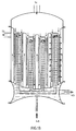
- FIGS. 12-15 show possible technical designs in which tube inserts are used in the manner of conventional tube bundle reactors.
- FIGS. 16-19 show individual tube inserts for such reactors, which can be screwed in, welded in, or inserted in the reactor body in another, generally known manner.
- reactors according to the invention can also be designed for a partial circulation of the reactants around the reactor (recirculation) in such a way that part of the reactor outlet is withdrawn as a product stream which is fed to the workup, while another part of the reactor outlet is returned to the Reactor input is returned to be used there again to complete the reaction or to serve as a native dilution for the starting materials.
- a part of the starting materials which has not yet passed through the catalyst layer can also recirculate; the latter is in FIGS. 14 and 15 are shown using the reactors from FIGS. 12 and 13.
- the partial recirculation of the product stream and especially the educt stream into the reactor inlet is at the same time suitable for increasing the flow rate of the educt stream between the heat exchanger surface and the catalyst surface, the heat transfer between the catalyst bed and the thermostatting medium or vice versa being improved.
- the educt recirculation is particularly suitable because the circulating educt flow along the entire "pipe length" is added as a constant amount to the educt flow passing through the catalyst, which is not the case with product recirculation and which leads to a particularly pronounced effect at the pipe end.
- a product circuit stream corresponding to the feed circuit flow discussed above may have to be installed, which, however, is not passed through the catalyst, as discussed above, but is fed to the product collection channels in accordance with the feed circuit flow discussed above.
- the reactors according to the invention are characterized in that the inflowing starting material strikes the largest possible catalyst bed area and at the same time the largest possible area for heat exchange is realized. This means that for a given space-time load there is a very low inflow load and the temperature of the catalyst is uniform. This in turn means that in the reactors according to the invention, unlike in the known reactors with continuous thermostatting, the heat flow with respect to the material flow through the catalyst is conducted in parallel, antiparallel or in parallel and antiparallel. In connection with this, the catalytically active beds in the reactors according to the invention have a particularly small expansion in the direction of flow.
- the catalyst bed is delimited in the reactors according to the invention by porous walls which, in addition to fixing the catalyst bed, have the task of guaranteeing a uniform flow through the catalyst bed over the entire surface.
- the flow resistance of these walls and the catalyst bed must exceed a certain minimum value, which the person skilled in the art can easily do experimentally or by calculation can be determined.
- the minimum flow resistance of the catalyst beds, including the porous gas distribution walls should be from 1 mbar to 10 bar, preferably from 2 mbar to 1 bar, particularly preferably from 5 mbar to 500 mbar.
- the porous walls in the reactors according to the invention preferably consist of sintered materials with a corresponding porosity, as are known to the person skilled in the art for gas distribution.
- Sintered shaped bodies made of metals are particularly preferred because of their good thermal conductivity.
- Pinhole constructions or mesh constructions can also be used. They too must meet the requirements to distribute the feed gas stream over the catalyst without major local fluctuations and to ensure a uniform flow through the bed; this also requires a sufficient flow resistance, which can also be generated at least partially by the catalyst bed.
- the catalyst material must be sufficiently fine-grained to ensure the required pressure drop at a sufficient level with the low penetration depth.
- the catalyst must have sufficient flow properties to ensure a uniform packing during the filling process; for example, the catalyst material must not tend to stick.
- the relationship between particle shape and size on the one hand and the Flow resistance of a bed of such particles, on the other hand, is known to the person skilled in the art and can be determined experimentally.
- the two walls used for fixing the catalyst bed and for gas distribution can also be replaced by an optionally layered or layered catalytically active molded body, which can consist entirely or partially of sintered material, preferably sintered metal, which is used simultaneously for gas distribution and as a carrier for the serves catalytically active material.
- Such a shaped body can be catalytically active in whole or in part.
- the basic possibilities for covering sintered materials with catalytically active particles are known to the person skilled in the art (EP 416 710).
- Another feature of the reactors according to the invention is the fact that the heat flow has to cross a small gas space in order to get from the gas distribution surface on the educt and / or product side to the surface in question, which limits the thermostatting medium and of course impermeable to the material flow is; the same applies to a heat flow reversed from the thermostatting medium to the gas distribution surface.
- the gap width that the heat flow has to bridge through the gas phase can be in the reactors according to the invention at 0.1-10 cm, preferably 0.2-8 cm, particularly preferably 0.3-6 cm, most preferably 0.4 - 4 cm.
- the targeted use of a heat flow resistance determined by the choice of the gap width of the gas space offers the possibility of placing the temperature difference between the thermostatting medium and the catalyst in a favorable and desired range when designing the reactor. For example, in connection with the extremely uniform heat accumulation over the entire exchanger surface, it is possible to place an oil thermostat in the temperature range that is favorable for the selected oil. This then means if, in a different design of the reactor, an oil as a heat transfer medium would have to be used for a more complicated salt melt.
- the temperature difference between the thermostatting medium and the catalyst surface in the reactors according to the invention can assume values of 2 to 250 ° C., preferably 5 to 200 ° C., particularly preferably 10 to 180 ° C. and very particularly preferably 20 to 130 ° C.
- the vector components of the flow velocity of the heat-transporting gases in the reactors according to the invention lying parallel to the gas distribution or product collection surface are set to values of 0-1000 m / sec, preferably 0-100 m / sec, particularly preferably 0-10 m / sec.
- the lower value zero in this area means the amount that the vector components at the end of the feed layers or at the beginning of the collection and discharge layers in constructions without starting material or product circulation assume.
- the surface shape of the pipes and gas distribution elements can be different from a smooth surface in order to generate turbulence, for example they can have ribs or similar additives.
- the conduct of the reaction is little to is partially adiabatic. More than 20%, preferably more than 40%, particularly preferably more than 60%, very particularly preferably more than 80%, very preferably more than 90% of the heat of reaction are removed or supplied via the thermostatting medium (heat transfer medium).
- the thermostatting medium heat transfer medium
- one or more additional heat transfer components can optionally be added to it. These components preferably result from the starting materials or products of the reaction.
- the embodiment of the reactor is chosen so that the amount of the temperature difference between the mean value of the inflow and outflow temperature of the catalyst bed surface and the temperature of the inside of the catalyst bed is at the hottest (exothermic reaction) or at the coldest (endothermic reaction) point is between 1 and 300 ° C, preferably between 1 and 200 ° C, particularly preferably between 1 and 100 ° C, very particularly preferably between 1 and 60 ° C, very preferably between 1 and 30 ° C.
- a reactor according to the invention can be provided with a pressure-resistant jacket, so that the reactions taking place in it can take place at above or below atmospheric pressure.
- reactors according to the invention In contrast to the known pressure reactors, it is possible in the case of reactors according to the invention to restrict the high-pressure part to the feed system and the actual catalyst bed by using outflow sintered bodies with a corresponding flow resistance.
- Such a construction offers the advantage that the structurally complex high-pressure space can be kept small.
- Table 1 shows the number of tubes of reactors according to the invention with a bed thickness of 1 cm and different tube diameters if the conventional comparative reactors accommodate 10,000 tubes with the same space-time loading and tube length.
- Table 1 Number of tubes of tube bundle reactors according to the invention in comparison to conventional tube bundle reactors ( ⁇ means diameter) conventional tube bundle reactors (10,000 tubes)
- Reactor tubes according to the invention with 40 cm ⁇ can be, for example, those as in FIG. 18, the thin-layer catalyst bed being designed as a hollow tube and being screwed over a pin for the passage of the heat transfer medium.
- Reactor tubes with 10 cm ⁇ according to the invention are, for example, those of the type shown in FIG. 16, the thin-layer catalyst layer again being designed as a hollow tube, but in contrast to FIG. 18 being screwed into a corresponding recess within the volume through which the heat transfer medium flows.
- the tube diameters of the tube bundle reactors according to the invention with a hollow cylindrical catalyst arrangement are in the range from 5 to 200 cm, preferably from 7 to 100 cm, particularly preferably from 10 to 50 cm.
- the pipe lengths range from 1-40 m, preferably from 2-20 m, particularly preferably from 3-10 m.
- the hollow catalyst cylinders according to the invention are generally used in a plurality of them as a larger unit, for example as a tube bundle.
- the reactors according to the invention can be used for any heterogeneously catalyzed gas phase reaction.
- they are particularly suitable for reactions that tend to have a pronounced hot spot in conventional tubular reactors, for reactions that must take place in a narrowly limited temperature range, for reactions whose catalyst is quickly overloaded and then tends to undergo side reactions, for Reactions that require a precisely defined dwell time, otherwise they tend to follow-up reactions, and finally for reactions that require extremely short dwell times with good cooling at the same time, because they run extremely quickly and then tend to follow-up reactions.
- the by-products and subsequent reaction products of a gas phase conversion which are caused by the temperature, the catalyst load or the residence time, can make a decisive contribution to deactivating the catalyst through coke formation. This is basically an undesirable deactivation similar to the catalyst deactivation due to temperature overload.
- the reactors according to the invention are therefore particularly well suited if long catalyst service lives are required it because the catalyst cannot be regenerated or because the technical implementation has to be as little maintenance-intensive as possible.
- the exact conduct of the reaction and the particularly low tendency to deactivate the catalysts in the reactors according to the invention can be explained by the low penetration depth of the catalyst beds and by the fact that low-volatility coke precursors can leave the catalyst bed before they have become stationary.
- Examples of reactions which can be carried out particularly favorably in the reactors according to the invention, without this list being exhaustive, are: dehydrogenations, e.g. from cyclohexylidene aniline to diphenylamine and from cyclohexenyl cyclohexanone to o-phenylphenol; Hydrogenations e.g. from nitrobenzene to aniline and from phenol to cyclohexanone; oxidative alcohol dehydrogenations e.g. from 3-methyl-3-buten-1-ol to 3-methyl-2-buten-1-al; Selective oxidations of hydrocarbons e.g. from n-butane to maleic anhydride, from o-xylene to phthalic anhydride and from propene to acrolein or acrylic acid as well as alkylations and halogenations.
- dehydrogenations e.g. from cyclohexylidene aniline to diphenylamine and from cyclohexeny
- the pretreated, dry carrier was impregnated with an aqueous sodium tetrachloropalladate solution, containing 18 g of Pd, corresponding to 0.216 gram equivalent, according to its absorbency and left to stand for 15 minutes.
- the catalyst was then washed in a flowing stream of distilled water until sodium and chloride ions were no longer detectable in the wash water, which was the case after 12 hours.
- the subsequent drying was carried out in a hot air stream, as previously described for drying the carrier.
- the catalyst produced in this way calculated as metal, contained 18 g of Pd per liter of support (1.555% by weight).
- the catalyst bed was between two beds of 5 mm glass balls.
- the oil jacket of the reactor was connected to a high temperature oil thermostat and the catalyst was heated to 250 ° C. in a stream of hydrogen.
- the hydrogen flow was replaced by a nitrogen flow and the temperature of the oil jacket was raised to 320 ° C.
- cyclohexylidene aniline was passed over the contact in a stream of nitrogen (1 l N2 / g cyclohexylidene aniline).
- diphenylamine in a nitrogen-hydrogen mixture left the reactor in gaseous form with 95% selectivity.
- the main sales zone was identified in the reactor bed by a temperature valley. This temperature valley moved over time from the catalyst head towards Catalyst end. After approx. 100 to 150 hours, the progressive deactivation of the catalyst became noticeable by a rapidly increasing proportion of cyclohexylidene aniline in the product mixture.
- the product gas was discharged through the inner glass tube, the outer glass tube, measured from the NS29 conical section to the lower end of the thermostatted glass tube, had a length of 25 cm.At the end of the thermostatted glass tube, the outer glass tube was sealed gas-tight with the thermostatted glass tube.
- the outer glass sintered tube was fused at the top with a 10 cm long glass tube with NS29 sleeve. An approx. 10 cm long evacuated glass ground stopper sat gas-tight in this sleeve.
- the catalyst bed was located between the outer and inner glass sintered tube.
- the oil jacket of the reactor was connected to a high temperature oil thermostat and the catalyst was heated to 250 ° C. in a hydrogen stream.
- the hydrogen flow was replaced by a nitrogen flow and the temperature of the oil jacket was raised to 320 ° C.
- cyclohexylidene aniline was passed in a nitrogen stream from the outside to the inside via the contact (1 l N2 / g cyclohexylidene aniline).
- diphenylamine in a nitrogen-hydrogen mixture left the reactor in gaseous form with 95% selectivity.
- the experiment was ended after 1000 hours of operation without any significant changes in the product composition (ie without catalyst deactivation).
- the solution was completely absorbed by the carrier within a few minutes.
- the moist carrier was poured into a vertical glass tube of approx. 2 l content and dried in a hot air flow of 120 ° C with an air volume of 25 Nm3 air per hour. The drying time to constant weight was about 30 minutes.
- the dry carrier pretreated in this way was impregnated with 366 ml of an aqueous sodium tetrachloropalladate (II) solution which contained 9 g of palladium, corresponding to 0.169 gram equivalent, in accordance with its absorbency and left to stand for 15 minutes.
- II aqueous sodium tetrachloropalladate
- the support was overlaid in a beaker with 400 ml of a 10% aqueous hydrazine hydrate solution and left to stand for 2 hours.
- the catalyst was then washed in a flowing stream of distilled water until no ions were present in the Compounds used in catalyst preparation were more detectable in the wash water, which was the case after 10 hours.
- the subsequent drying was carried out in a hot air stream, as previously described for drying the carrier.
- the catalyst prepared in this way contained 9 g of palladium per liter of support.
- the Pd-containing catalyst was then impregnated with 366 ml of an aqueous solution containing 9 g of vanadium in the form of vanadyl oxalate.
- the drying of the Pd catalyst impregnated with vanadyl oxalate was carried out analogously to the drying of the support in a hot air stream at 120 ° C.
- the subsequent decomposition of the vanadyl oxalate was carried out at 300 ° C. for 6 hours.
- the catalyst was impregnated with 366 ml of an aqueous solution containing 3 g of lead in the form of lead acetate.
- the catalyst impregnated with lead acetate was filled into a tubular reactor in the moist state and dried during the heating period of the heat transfer medium.
- the activation of the catalyst was carried out in a stream of hydrogen at the temperature of the heat transfer medium, which was 280 ° C.
- the finished catalyst, calculated as metal, contained 9 g palladium, 9 g vanadium and 3 g lead per liter of support.
- a 15 cm catalyst bed was placed in the middle of the glass reactor described in Example 2. After activation in a hydrogen stream, nitrobenzene was passed over the contact at an oil bath temperature of 220 ° C. with a load of 0.5 g / ml h and an excess of hydrogen of 250%. A hot zone with a maximum temperature of approx. 360 ° C formed on the catalyst. This hot zone flattened toward the end of the catalyst. After a running time of approx. 1000 hours, nitrobenzene started to leave the reactor with the product gas mixture. Before the deactivation reached the end of the catalyst, aniline with a selectivity of better than 99.5% was formed at 100% conversion.
- the hollow cylinder reactor described in Example 3 received another vacuum double jacket insert with fused glass sintered hollow cylinder in exchange. Length of the glass sinter tube melted at the upper end 15 cm, diameter 1.2 cm. The radial flow Bed thickness increased from 6 mm to 10 mm. The space between the glass sintered tubes was filled with catalyst.
- Example 5 the catalyst was operated after a pre-reduction at an oil bath temperature of 220 ° C. and a load of 0.5 g of nitrobenzene per ml of catalyst per hour with a 250% excess of hydrogen.
- a temperature of 320 ° C. was measured in the interior of the inner glass sintered tube by means of a temperature sensor.
- the experiment was ended after 4000 hours of running time without significant deactivation of the catalyst. During this period, 100% of nitrobenzene was converted and aniline was formed with more than 99.8% selectivity.
- Example 7 The experiment from Example 7 was repeated at an oil temperature of 320 ° C.
- the outlet temperature of the product gas mixture inside the reactor was 430 ° C. After a running time of 600 hours, the product composition and outlet temperature were unchanged (conversion 100%, selectivity> 99.8%); Only after 800 hours of running time did catalyst deactivation begin.
Landscapes
- Chemical & Material Sciences (AREA)
- Organic Chemistry (AREA)
- Chemical Kinetics & Catalysis (AREA)
- Physics & Mathematics (AREA)
- Fluid Mechanics (AREA)
- Organic Low-Molecular-Weight Compounds And Preparation Thereof (AREA)
- Devices And Processes Conducted In The Presence Of Fluids And Solid Particles (AREA)
- Catalysts (AREA)
- Physical Or Chemical Processes And Apparatus (AREA)
Abstract
Description
- Die Erfindung betrifft Festbettreaktoren zur Umsetzung von gasförmigen Edukten oder Eduktgemischen, die dadurch gekennzeichnet sind, daß die Edukte oder Eduktgemische ein flächig ausgebildetes Katalysatorbett annähernd oder gänzlich senkrecht zu diesen Flächen durchströmen.
- Hierbei ist es möglich, die Funktion, welche die Temperatur und die Eduktbelastung in Abhängigkeit vom Ort im Katalysatorbett beschreibt, möglichst flach verlaufen zu lassen, wodurch partielle Überlastungen und - speziell bei stark exothermen Reaktionen - Temperaturspitzen zu vermeiden.
- Diese Charakteristiken der erfindungsgemäßen Reaktoren ergeben optimale Selektivitäten und Katalysatorstandzeiten.
- Die Erfindung betrifft ferner die Verwendung solcher Festbettreaktoren für die Umsetzung von gasförmigen Edukten beziehungsweise Eduktgemischen.
- Die katalytische Umsetzung von Gasen an stationären Kontakten läßt sich leicht als kontinuierlicher Prozeß führen und besitzt die reizvolle Annehmlichkeit, daß das Produkt im allgemeinen nicht von Hilfsstoffen, wie Lösungsmitteln oder Katalysatoren, abzutrennen ist. Dementsprechend werden in der chemischen Industrie bevorzugt Chemikalien mit mittlerer und großer Produktionsmenge auf diesem Weg erzeugt.
- Viele organische Verbindungen sind im gasförmigen Aggregatzustand bedeutend stabiler als im flüssigen, da aufgrund der geringen räumlichen Konzentration bi- und höhermolekulare Nebenreaktionen unterdrückt werden, so daß beispielsweise stark exotherme Reaktionen auf einem höheren Temperaturniveau durchgeführt werden können als im flüssigen Zustand, was wiederum für eine gekoppelte Wärmeenergiegewinnung von Vorteil ist.
- Andere Reaktionen, beispielsweise endotherme Spaltreaktionen, benötigen besonders hohe Temperaturen und können, insbesondere bei empfindlichen Edukten und Produkten, fast nur in der Gasphase durchgeführt werden.
- In der Literatur ist eine Vielzahl von Reaktortypen beschrieben (Ullmanns, Enzyklopädie der technischen Chemie, 4. Aufl., Bd. 3, S. 468-649; Kirk-Othmer, Encyclopedia of Chemical Technology, Vol. 19 (1982), S. 880-914). Man unterscheidet dabei Reaktoren mit gelenktem und mit ungelenktem Temperaturprofil.
- Reaktoren mit ungelenktem Temperaturprofil bestehen aus einer Katalysatorschüttung beziehungsweise aus einem aus katalytisch aktiven Formkörpern gebildeten Katalysatorbelt in einem mehr oder weniger gut isolierten Gefäß von einfacher Geometrie.
- Die Reaktionsenthalpie wird in solchen Reaktoren dem Produktgemisch mitgegeben; daher bezeichnet man diese Konstruktionen als adiabatisch. Der Hauptreiz dieser Reaktoren besteht in ihrem einfachen und damit preiswerten und wartungsfreundlichen Aufbau. Bei der Verwendung solcher adiabatischer Reaktoren mit ungelenktem Temperaturprofil ist jedoch zu berücksichtigen, daß chemische Umwandlungen sowohl in kinetischer als auch in thermodynamischer Hinsicht einen exponentiellen Charakter haben und damit sehr empfindlich auf Temperaturänderungen reagieren. Das heißt, daß viele Reaktionen nur in einem engen Temperaturbereich mit genügender Selektivität und Geschwindigkeit ablaufen. Auch der Katalysator selbst kann sich als temperaturempfindlich erweisen.
- Da nun die meisten chemischen Reaktionen im Verhältnis zur Wärmekapazität der Systeme eine deutliche Wärmetönung besitzen, kann nur in sehr wenigen Fällen auf die Ab- beziehungsweise Zufuhr von thermischer Energie zur Einhaltung des erforderlichen Temperaturbereichs verzichtet werden (gelenktes Temperaturprofil).
- Bei den Reaktoren mit gelenktem Temperaturprofil unterscheidet man die kontinuierliche von der stufenweisen Thermostatisierung baziehungsweise Wärmeabfuhr oder Wärmezufuhr. Die stufenweise Thermostatisierung zerlegt im Prinzip einen adiabatischen Reaktor in Teilabschnitte, nach deren Verlassen das Gas in thermische Wechselwirkung mit einem Wärmeträger gebracht wird oder frische Eduktmischung mit passender Temperatur zugemischt bekommt (Ullmann, loc. cit., S. 473). Die Reaktion darf bei diesem Reaktortyp thermisch nicht zu anspruchsvoll sein, da sonst eine sehr große Stufenzahl erforderlich ist, um die Temperaturgrenzen einzuhalten. Andererseits sind speziell für die Ammoniak- und Methanol-Synthese sehr komplizierte Reaktorkonstruktionen zur optimalen Unterbringung und zum optimalen Betrieb einer größeren Zahl von Katalysatorbettabschnitten und Wärmeaustauschern in einem Hochdruckraum entwickelt worden (EP 297 474, EP 333 757 und darin genannte Literatur).
- Für Reaktionen mit extrem starker Wärmetönung und Katalysatoren beziehungsweise Reaktionen mit extrem empfindlichem Temperaturverhalten ist daher eina kontinuierliche Thermostatisierung einzurichten. Hierbei kann man den Katalysator entweder zwischen den Rohran oder in den Rohren eines Wärmetauschers unterbringen (Linde-Reaktor gemäß DE-OS 34 14 714 beziehungsweise Rohrbündelreaktor gemäß Chemie-Ingenieur-Technik 51 (1979), S. 257-265). Reaktoren dieser Art mit Rohrdurchmessern von einem bis zu mehreren cm und Rohrlängen von 2-20 m sind seit langem Stand der Technik. Trotz des ständigen Wärmeflusses in radialer Richtung bildet sich bei stark exothermen Reaktionen ein "hot-spot" in den Reaktorrohren aus, welcher für Selektivitätsverluste oder Katalysatorschädigungen verantwortlich zu machen ist. Es ist bereits beschrieben, den "hot-spot" zu verkleinern, indem der Katalysator zu Beginn der Schüttung mit inertem Material verdünnt wird oder indem die Reaktorrohre am Einströmende einen geringeren Durchmesser besitzen als am Ausströmende (DE-OS 29 29 399; GB 2.132.111). Es ist weiterhin beschrieben, den Mangel an einheitlicher Thermostatisierung durch eine Verkürzung der Rohre des Rohrbündelreaktors auf 1-30 cm, bevorzugt 5-20 cm, zu beheben (DE-OS 36 12 213, EP 244 632). Die Rohre eines solchen Kurzrohrreaktors besitzen Innendurchmesser von 0,5-3 cm, bevorzugt 1-2 cm. Die Vorteile dieses Kurzrohrreaktors werden wie folgt beschrieben:
Große spezifische Kühlfläche und gleichmäßige seitliche Anströmung der Rohre durch den Wärmeträger führen zu definierter Temperaturverteilung im Reaktorrohr, gleichmäßige Queranströmung aller Rohre durch den Wärmeträger soll zu kompakter Bauweise mit maximalem Wärmeübergang führen; auch bei feinkörnigem Katalysator soll es nur einen geringen Druckabfall in den Rohren geben. - In der genannten EP 244 632 wird ferner eine Verbindung zwischen Rohrlänge und Verweilzeit geknüpft, ohne auf diese näher einzugehen; das kurze Rohr mit kurzer Verweilzeit und guter Wärmeabfuhr wird als günstig für stark exotherme Reaktionen mit hoher Aktivierungsenergie und thermisch instabilen Reaktanden und Produkten beschrieben. Hiebei wird jedoch nicht auf die Zahl der Rohre eingegangen, die ain Kurzrohrbündelreaktor beherbergen muß, dessen Rohrlänge um den Faktor 50-500 unter der eines gängigen Reaktors liegt, um technisch relevante Produktmengenströme zu ermöglichen. Zur Substitution eines in der Technik nicht selten anzutreffenden Reaktors mit 10.000 Rohren Üblicher Länge wären dies beim Kurzrohrbündelreaktor 500.000 bis 5 Mio Kurzrohreinbauten. Ebenso wenig wird auf die gleichmäßige Durchströmung der riesigen Rohrzahl eingegangen, noch auf die Art, wie dies gewährleistet werden soll, noch auf die Art, wie die Rohre befüllt werden sollen. Die genannte EP 244 632 befaßt sich ausschließlich mit dar Verweilzeit und dar gleichmäßigen Thermostatisierung, de nach der bakannten Lehre die Aufströmbelastung eines Katalysatorbettes (1 Eduktmischung pro m² Aufströmoberfläche des Katalysatorbettes und Stunde) im allgemeinen keine besonders charakteristische Größe für die Eigenschaften einer heterogenen katalysierten Gasphasenumsetzung ist.
- Die Erfindung betrifft Reaktoren für die kontinuierliche Umsetzung gasförmiger Stoffe an Festbettkatalysatoren bei kontinuierlicher Temperaturlenkung mit Hilfe eines Wärmeträgers, die gekennzeichnet sind durch die Ausbildung des Katalysatorbettes in Form von einer oder mehreren regelmäßig geformten flächigen Schichten mit einer Dicke von 0,01-50 cm, wobei die Oberfläche der Katalysatorschichten durch eine für Gase durchlässige Schicht abgeschlossen ist und wobei diese Oberfläche auf der Eduktanströmseite und/oder auf der Produktaustrittsseite in einem Abstand von 0,1-10 cm einer in gleicher Weise regelmäßig geformten Wandung gegenüber steht, die den Raum für die umzusetzenden Stoffe beziehungsweise umgesetzten Stoffe vom Raum für den Wärmeträger trennt, und gekennzeichnet sind durch eine solche Führung der umzusetzenden Stoffe, daß diese das Katalysatorbett annähernd oder gänzlich senkrecht zu den flächigen Katalysatorschichten durchströmen.
- Die Erfindung betrifft weiterhin den Einsatz der erfindungsgemäßen Reaktoren in Verfahren zu katalysierten, thermogelenkten Gasphasenreaktionen mit hoher endothermer oder exothermer Wärmetönung.
- Die beigefügten Zeichnungen zeigen den prinzipiellen Aufbau und die prinzipielle Wirkungsweise der erfindungsgemäßen Reaktoren und einige denkbare technische Ausführungsvarianten.
- Die erfindungsgemäßen Reaktoren erlauben es, die Funktion, welche die Temperatur und die Eduktbelastung in Abhängigkeit vom Ort im Katalysatorbett beschreibt, möglichst flach verlaufen zu lassen. Hierdurch werden partielle Überbelastungen und - speziell bei stark exothermen Reaktionen - Temperaturspitzen vermieden. Damit wird es möglich, Nebenreaktionen durch Katalysatorüberlastung oder durch ungeeignete Katalysatortemperatur zu unterdrücken, was sowohl der Selektivität der Produktherstellung als auch der Katalysatorstandzeit zugute kommt. Diese Vorteils werden im erfindungsgemäßen Reaktor dadurch erreicht, daß das Katalysatorbett in Strömungsrichtung eine besonders geringe Ausdehnung erhält und zum anderen dadurch, daß die Reaktionswärme parallel, antiparallel oder parallel und antiparallel zur Strömungsrichtung der Stoffe durch das Katalysatorbett aus der Reaktionszone abgeführt oder der Reaktionszone zugeführt wird. Ein weiterer günstiger Effekt der geringen Durchdringungstiefe solcher gleichmäßig temperierter und belasteter Katalysatorbetten ist ihr geringes Rückhaltevermögen für schwerflüchtige Nebenprodukte, was zusätzlich extrem lange Katalysatorstandzeiten fördert. Im folgenden wird hauptsächlich auf eine Thermostatisierung durch einen sekundären Wärmekreislauf als einer wichtigen technischen Ausführungsform eingegangen; es ist dennoch grundsätzlich möglich, auch eine direkte Wasserdampf-Thermostatisierung oder eine andere vergleichbare direkte Thermostatisierung in den erfindungsgemäßen Reaktoren durchzuführen.
- Die erfindungsgemäßen Festbettreaktoren erlauben eine gleichmäßige Belastung und Thermostatisierung des eingesetzten Katalysators. Ein erfindungsgemäßer Reaktor für großtechnische Anwendungen beherbergt trotzdem nur eine geringe Anzahl von Einbauten, die ferner preiswert und leicht zu warten sind.
- In den beigefügten Zeichnungen bedeuten die Pfeile mit durchgezogenen Linien und der Bezugsziffer (1) den jeweiligen Stoffstrom von der Zuführung des Edukts (1a) (Ausgangsstoff/-stoffgemisch, gegebenenfalls gemeinsam mit einem Verdünnungs- oder Trägergas) zur Abführung des Produkts (1b) (Reaktionserzeugnis/Reaktionsgemisch, gegebenenfalls mit verdünnung/Trägergas). Die Pfeile mit gestrichelten Linien und der Bezugsziffer (2) bedeuten den Wärmestrom vom Katalysator zum Wärmeträger. In den beigefügten Zeichnungen zeigen gestrichelte Pfeile zur Illustrierung der Wärmeströme am Katalysator den Fall einer exothermen Reaktion. Endotherme Umsetzungen besitzen einen zur Pfeilrichtung diametralen Wärmefluß; solche Verhältnisse sind in den Zeichnungen explizit nicht berücksichtigt. Die punktierten, schmalen Flächen (3) bedeuten das durch eine für Gase durchlässige Schicht abgeschlossene Katalysatorbett; die für Gase durchlässige Schicht ist in den Zeichnungen nicht besonders hervorgehoben. Die waagerecht gestrichelten Flächen (4) bedeuten den durch eine Wandung abgeschlossenen Raum für den Wärmeträger. Der Wärmeträger gilt in einer dem Fachmann bekannten Weise als durch den erfindungsgemäßen Reaktor bewegt und als mit einer externen Heizung/Kühlung für die Temperaturlenkung endothermer/exothermer Reaktionen verbunden. Wo es in den Zeichnungen beispielhaft gezeigt werden soll, wird der Wärmeträgerstrom durch Pfeile mit Doppelstrich und den Ziffern (4a) für den Eintritt beziehungsweise (4b) für den Austritt bezeichnet.
- Figur 1 zeigt das Prinzip des erfindungsgemäßen Reaktors am Schnitt durch ein ebenes, flaches Katalysatorbett mit gegenüber liegenden Wärmeträgerräumen; Figur 2 zeigt das Prinzip am Schnitt durch ein als Hohlzylinder ausgebildetes Katalysatorbett; Figur 3 zeigt im Gegensatz hierzu einen Rohrreaktor gemäß Stand der Technik, ebenfalls im Schnitt. Während beim erfindungsgemäßen Reaktor Stoff- und Wärmestrom stets parallel, antiparallel oder sowohl parallel als auch antiparallel zueinander verlaufen, stehen im herkömmlichen Reaktor Stoff- und Wärmestrom orthogonal zueinander. Folgerichtig sind im erfindungsgemäßen Reaktor die von Stoff- und Wärmestrom durchströmten Flächen stets identisch, während sie dies im herkömmmlichen Reaktor nicht sein können.
- Figuren 4 - 9 zeigen Variationen von Figur 1 und Figur 2, bei denen in Abwandlung der Bauausführung - flaches Katalysatorbett oder Hohlzylinder als Katalysatorbett beziehungsweise Zu- und Abfuhr von Edukt und Produkt beziehungsweise Notwendigkeit der Energiezufuhr oder Energieabfuhr (bei endothermer oder exothermer Reaktion) - eins parallele oder antiparallele Führung von Edukt-zu Produktstrom in den Verteilungs- und Sammelschichten und eine parallele, antiparallele oder sowohl parallele als auch antiparallele Stoff- zu Wärmefluß-Führung im Katalysatorbett gezeigt wird. Als Wärmefluß ist hierbei derjenige zu verstehen, der vom Katalysatorbett zur Wandung mit dem Wärmeträgerraum oder in umgekehrter Richtung strömt. Die zusätzliche Ziffernbezeichnung der Zeichnungssymbole wurde der Übersichtlichkeit halber in den Figuren 4 -9 fortgelassen. Es ist ersichtlich, daß die Figuren 4 und 5 der Figur 1 zugeordnet sind und die Figuren 6 -9 der Figur 2. In den Figuren 4 und 5 bewegt sich der Wärmestrom sowohl parallel als auch antiparallel zum Stoffstrom; in den Figuren 6 - 9 ist dies entweder parallel oder antiparallel.
- Das Katalysatorbett kann in einer oder mehreren flächigen Schichten ausgebildet werden. So können die flächigen Katalysatorschichten und die gegenüber stehenden, in gleicher Weise regelmäßig geformten Wandungen der Wärmeträgerräume in einer paketähnlichen Anordnung vereinigt werden (Figur 10); die Kombination aus flächigem Katalysator und Wärmeträgerraum kann jedoch auch in einer "aufgerollten" zylindrischen Form angeordnet werden (Figur 11a). Wenn hierbei in der Gesamtanordnung Stoff- und Wärmeträgerfluß auch in orthogonaler Richtung zueinander stehen, trifft dies in der oben geschilderten Weise für das Katalysatorbett im einzelnen nicht zu, wie in Fig. 11b gezeigt wird; in Fig. 11b wird der Wärmeträger im Sinne einer Spirale gelenkt und thermostatisiert sowohl die Edukt- als auch die Produktseite.
- Die Figuren 12 - 15 zeigen mögliche technische Ausführungen, bei denen Rohreinsätze in der Art herkömmlicher Rohrbündelreaktoren Verwendung finden. Die Figuren 16 -19 zeigen einzelne Rohreinsätze für solche Reaktoren, die eingeschraubt, eingeschweißt oder auf andere, grundsälzlich bekannte Weise in den Reaktorkörper eingesetzt werden können.
- Technische Ausführungsformen der erfindungsgemäßen Reaktoren können auch für einen teilweisen Umlauf der Reaktionspartner um den Reaktor (Rezirkulation) in der Weise ausgelegt werden, daß ein Teil des Reaktorablaufs als Produktstrom entnommen wird, der der Aufarbeitung zugeführt wird, während ein weiterer Teil des Reaktorablaufs erneut an den Reaktoreingang zurückgeführt wird, um dort zur Vervollständigung der Reaktion erneut eingesetzt zu werden oder als systemeigene Verdünnung für die Edukte zu dienen. In entsprechender Weise kann auch ein Teil der Edukte, der noch nicht durch die Katalysatorschicht getreten ist, rezirkulieren; letzteres ist in Figur 14 und 15 anhand der Reaktoren aus den Figuren 12 und 13 gezeigt. Die teilweise Rückführung des Produktstromes und besonders des Eduktstromes in den Reaktoreingang ist gleichzeitig dazu geeignet, die Strömungsgeschwindigkeit des Eduktstromes zwischen der Wärmeaustauscherfläche und der Katalysatoroberfläche zu erhöhen, wobei der Wärmeübergang zwischen Katalysatorbett und Thermostatisiermedium beziehungsweise umgekehrt verbessert wird. In besonderer Weise ist die Eduktrückführung dazu geeignet, weil sich der zirkulierende Eduktstrom entlang der gesamten "Rohrlänge" dem durch den Katalysator tretenden Eduktstrom als konstanter Betrag zuaddiert, was bei der Produktrezirkulation nicht der Fall ist und was am Rohrende zu einem besonders ausgeprägten Effekt führt.
- Für Reaktoren mit produktseitiger Thermostatisierung ist gegebenenfalls ein dem oben diskutierten Eduktkreisstrom entsprechender Produktkreisstrom zu installieren, der jedoch nicht, wie weiter oben diskutiert, durch den Katalysator geführt wird, sondern entsprechend dem oben diskutierten Eduktkreisstrom den Produktsammelkanälen zugeführt wird.
- Gegebenenfalls können alle drei Varianten zur Verbesserung des Wärmeübergangs gleichzeitig realisiert werden.
- Die gezeigten beispielhaften Ausführungsformen machen ferner deutlich, daß in den erfindungsgemäßen Reaktoren über die gesamte Wärmeaustauschfläche eine gleichmäßige Wärmeabgabe beziehungsweise -zufuhr erzielt wird, wobei eine einfachere Reaktorkonstruktion auf der Seite des Thermostatisiermediums ermöglicht wird.
- Die erfindungsgemäßen Reaktoren sind dadurch gekennzeichnet, daß das anströmende Edukt auf eine möglichst große Katalysatorbettfläche trifft und gleichzeitig eine möglichst große Fläche zum Wärmeaustausch realisiert wird. Das bedeutet, daß bei einer gegebenen Raum-Zeit-Belastung eine sehr niedrige Aufströmbelastung vorliegt und der Katalysator gleichmäßig temperiert ist. Das wiederum bedeutet, daß in den erfindungsgemäßen Reaktoren, anders als in den bekannten Reaktoren mit kontinuierlicher Thermostatisierung, der Wärmestrom bezüglich des Stoffstroms durch den Katalysator parallel, antiparallel oder parallel und antiparallel geführt wird. Im Zusammenhang hiermit besitzen die katalytisch aktiven Betten in den erfindungsgemäßen Reaktoren eine besonders geringe Ausdehnung in Strömungsrichtung. Diese bewegt sich bei 0,01-50 cm, bevorzugt bei 0,02-20 cm, besonders bevorzugt bei 0,05-10 cm, ganz besonders bevorzugt bei 0,1-5 cm, ausgesprochen bevorzugt bei 0,2-2 cm. Die Katalysatorschüttung wird in den erfindungsgemäßen Reaktoren durch poröse Wände begrenzt, die neben der Fixierung der Katalysatorschüttung die Aufgabe haben, die gleichmäßige Durchströmung des Katalysatorbetts über die gesamte Oberfläche zu garantieren. Hierzu muß der Strömungswiderstand dieser Wände und des Katalysatorbettes einen gewissen Mindestwert überschreiten, der vom Fachmann leicht experimentell oder durch Rechnung ermittelt werden kann. Im allgemeinen soll der Mindestströmungswiderstand der Katalysatorbetten einschließlich der porösen Gasverteilungswände Werte von 1 mbar bis 10 bar, bevorzugt von 2 mbar bis 1 bar, besonders bevorzugt von 5 mbar bis 500 mbar liegen.
- Die porösen Wände in den erfindungsgemäßen Reaktoren bestehen bevorzugt aus Sinterwerkstoffen mit einer entsprechenden Porosität, wie sie zur Gasverteilung dem Fachmann bekannt sind, Besonders bevorzugt sind Sinterformkörper aus Metallen wegen ihrer guten Wärmeleitfähigkeit. Des weiteren sind auch Lochblendenkonstruktionen oder Maschengeflechtkonstruktionen brauchbar. Auch sie müssen die Voraussetzungen erfüllen, den Eduktgasstrom ohne größere örtliche Schwankungen auf den Katalysator zu verteilen und eine gleichmäßige Durchströmung der Schüttung zu gewährleisten; hierzu ist ebenfalls wieder ein genügender Strömungswiderstand erforderlich, der auch mindestens teilweise von der Katalysatorschüttung erzeugt werden kann. Zu diesem Zweck muß das Katalysatormaterial genügend feinkörnig sein, um bei der geringen Durchdringungstiefe den erforderlichen Druckabfall in ausreichender Höhe zu gewährleisten. Es ist ferner verständlich, daß der Katalysator eine ausreichende Rieselfähigkeit haben muß, um beim Vorgang des Einfüllens eine einheitliche Packung zu gewährleisten; so darf das Katalysatormaterial beispielsweise nicht zur Verklebung neigen. Der Zusammenhang zwischen Partikelform und -größe einerseits und dem Strömungswiderstand einer Schüttung aus solchen Partikeln andererseits ist dem Fachmann bekannt und kann experimentell ermittelt werden. Die beiden zur Fixierung der Katalysatorschüttung und zur Gasverteilung dienenden Wände können auch durch einen gegebenenfalls schichtförmigen bzw. aus Schichten aufgebauten katalytisch aktiven Formkörper, der ganz oder teilweise aus Sintermaterial, bevorzugt Sintermetall bestehen kann, ersetzt werden, der gleichzeitig zur Gasverteilung und als Träger für das katalytisch aktive Material dient. Ein solcher Formkörper kann ganz oder teilweise katalytisch aktiv sein. Die prinzipiellen Möglichkeiten zur Belegung von Sinterwerkstoffen mit katalytisch aktiven Partikeln sind dem Fachmann bekannt (EP 416 710).
- Ein weiteres Merkmal der erfindungsgemäßen Reaktoren ist ferner die Tatsache, daß der Wärmestrom eine kleine Gasraumstrecke durchqueren muß, um von der Gasverteilungsoberfläche auf der Edukt- und/oder Produktseite zur jeweils infrage kommenden Oberfläche zu gelangen, die das Thermostatisiermedium eingrenzt und selbstverständlich für den Stoffstrom undurchlässig ist; das gleiche gilt für einen Wärmestrom umgekehrt vom Thermostatisiermedium zur Gasverteilungsoberfläche.
- Beim Einsatz von umzusetzenden Gasen, die eine geringe Wärmeleitfähigkeit haben, ist es günstig, die Länge des Gasweges zwischen Katalysator und der Trennwand zum Thermostatisiermedium kürzer auszubilden, Es ist zwar prinzipiell möglich, auch bei Gasen mit schlechter Wärmeleitfähigkeit eine große Gaswegstrecke vorzusehen und die Wärmeleitung durch Kühlblechkonstruktionen aus Metall, die von der Trennfläche zum Thermostatisiermedium ausgehen, zu bewirken. Eine solche Konstruktion ist jedoch kompliziert und daher nicht bevorzugt.
- Eine weitere Möglichkeit zur Benutzung großer Wegstrecken für die Gase bei schlechter Wärmeleitung ist die Erhöhung der Strömungsgeschwindigkeit, wie dies weiter oben bereits beschrieben wurde und durch einen teilweisen Umlauf des Edukts und/oder des Produkts zum Reaktoreingang und/oder des Produktes in die Sammelkanäle realisiert werden kann. Die Spaltbreite, die der Wärmestrom durch die Gasphase zu überbrücken hat (Abstand zwischen Katalysatorbett und Wandung zum Thermostatisierungsmedium), kann in den erfindungsgemäßen Reaktoren bei 0,1 -10 cm, bevorzugt 0,2 - 8 cm, besonders bevorzugt 0,3 -6 cm, ganz besonders bevorzugt 0,4 - 4 cm liegen.
- Der gezielte Einsatz eines durch Wahl der Spaltbreite des Gasraumes festgelegten Wärmeströmungswiderstandes bietet die Möglichkeit, den Temperaturunterschied zwischen dem Thermostatisiermedium und dem Katalysator bei der Auslegung des Reaktors in einen günstigen und gewünschten Bereich zu legen. So ist es beispielsweise möglich, im Zusammenhang mit dem außerordentlich gleichmäßigen Wärmeanfall über die gesamte Austauscherfläche, eine Ölthermostatisierung in den für das gewählte Öl günstigen Temperaturbereich zu legen. Dies hat dann Bedeutung, wenn bei anderer Auslegung des Reaktors von einem Öl als Wärmeträger auf eine komplizierer zu handhabende Salzschmelze übergegangen werden müßte.
- Die Temperaturdifferenz zwischen dem Thermostatisiermedium und der Katalysatoroberfläche kann in den erfindungsgemäßen Reaktoren Werte von 2 bis 250°C, bevorzugt 5 bis 200°C, besonders bevorzugt 10 bis 180°C und ganz besonders bevorzugt von 20 bis 130°C annehmen.
- Die parallel zur Gasverteilungs- oder Produktsammeloberfläche liegenden Vektorkomponenten der Strömungsgeschwindigkeit der die Wärme transportierenden Gase in den erfindungsgemäßen Reaktoren werden auf Werte von 0 - 1000 m/sec, bevorzugt von 0 - 100 m/sec, besonders bevorzugt 0 - 10 m/sec eingestellt. Der untere Wert Null in diesem Bereich bedeutet hierbei den Betrag den die besagten Vektorkomponenten am Ende der Zuführungsschichten beziehungsweise am Anfang der Sammel- und Ableitungsschichten in Konstruktionen ohne Edukt- beziehungsweise Produktumlauf annehmen.
- Die Oberflächenform der Rohre und Gasverteilungselemente kann zur Erzeugung von Turbulenzen von einer glatten Fläche unterschiedlich sein, also beispielsweise Rippen oder ähnliche Zusätze aufweisen.
- Für die halbseitig thermostatisierten Reaktortypen gilt, daß die Reaktionsführung in Abhängigkeit von der Bettdicke, der Wärmeleitfähigkeit des Katalysatorbettes, des Gasverteilungssystems und der Gasströme wenig bis teilweise adiabatisch ist. Es werden mehr als 20 %, bevorzugt mehr als 40 %, besonders bevorzugt mehr 60 %, ganz besonders bevorzugt mehr als 80 %, ausgesprochen bevorzugt mehr als 90 % der Reaktionswärme über das Thermostatisiermedium (Wärmeträger) ab- beziehungsweise zugeführt. Zur Verbesserung der Wärmekapazität des umzusetzenden Gasgemisches kann gegebenenfalls diesem eine oder mehrere zusätzliche Wärmeträgerkomponenten zugefügt werden. Diese Komponenten ergeben sich bevorzugt aus den Edukten beziehungsweise Produkten der Umsetzung.
- Für die doppelseitig thermostatisierten Reaktortypen gilt, daß die Ausführungsform des Reaktors so gewählt wird, daß der Betrag der Temperaturdifferenz zwischen dem Mittelwert von Ein- und Ausströmtemperatur der Katalysatorbettoberfläche und der Temperatur des Katalysatorbettinneren am heißesten (exotherme Reaktion) beziehungsweise am kältesten (endotherme Reaktion) Punkt zwischen 1 und 300°C, bevorzugt zwischen 1 und 200°C, besonders bevorzugt zwischen 1 und 100°C, ganz besonders bevorzugt zwischen 1 und 60°C, ausgesprochen bevorzugt zwischen 1 und 30°C liegt.
- Obengenannte Temperaturdifferenzgrenzen gelten ebenfalls für die halbseitig thermostatisierten Ausführungsformen.
- Entsprechend dem Stand der Technik kann ein erfindungsgemäßer Reaktor mit einer druckfesten Ummantelung versehen werden, so daß die in ihm ablaufenden Reaktionen bei über- oder unteratmosphärischem Druck ablaufen können.
- Im Unterschied zu den bekannten Druckreaktoren ist es bei erfindungsgemäßen Reaktoren möglich, den Hochdruckteil auf das Zuleitungssystem und das eigentliche Katalysatorbett zu beschränken, indem man Ausströmsinterkörper mit einem entsprechenden Strömungswiderstand verwendet.
- Eine derartige Konstruktion bietet den Vorteil, daß der konstruktiv aufwendige Hochdruckraum klein gehalten werden kann.
- Bevorzugt werden hierfür z.B. Konstruktionen verwendet, wie sie in Figur 13 und 15 gezeigt sind.
- Für Hochdruckreaktionen mit nur teilweisem Umsatz und einer entsprechenden Eduktrecyclisierung ist bei den erfindungsgemäßen Reaktoren hervorzuheben, daß das System auf einen sehr geringen Strömungswiderstand hin optimiert werden kann bei gleichzeitig sehr guter Thermostatisierung, was geringe Pumpleistungen zur Rückführung der komprimierten viskosen Gase zur Folge hat.
- Anhand einer Hohlzylinderkonstruktion soll im folgenden auf die Menge der Einbauten in einem solchen Reaktortyp und auf ihre Dimensionierung eingegangen werden. Die Tendenz bei herkömmlichen Rohrbündelreaktoren, zwecks besserer Reaktionskontrolle zu immer kleineren Einbauten überzugehen, seien es nun immer dünnere Rohre oder immer kürzere, führt zu einer Steigerung der Anzahl der Rohre. Technische Reaktoren herkömmlicher Bauart besitzen nicht selten 10.000 Rohre oder mehr. Bei dem in der oben bereits genannten EP 244 632 beschriebenen Kurzrohrreaktor würde sicher eine Anzahl an Rohren von 100.000 erreicht oder überschritten. Am Beispiel von erfindungsgemäßen Rohrbündelreaktoren mit radialem Wärme- und Stofffluß (also parallel oder antiparallel oder sowohl parallel als auch antiparallel) soll verdeutlicht werden, daß mit dem erfindungsgemäßen Reaktorprinzip die Tendenz zu immer zahlreicheren Einbauten durchbrochen wird. Als Vergleichsreaktoren sollen konventionelle Rohrbündelreaktoren mit Rohrinnendurchmessern von 1,5 beziehungsweise 2,5 cm betrachtet werden. Tabelle 1 zeigt die Rohranzahl von erfindungsgemäßen Reaktoren mit einer Bettdicke von 1 cm und unterschiedlichen Rohrdurchmessern, wenn bei gleicher Raumzeitbelastung und Rohrlänge die konventionellen Vergleichsreaktoren 10.000 Rohre beherbergen.
Tabelle 1 Rohranzahl von erfindungsgemäßen Rohrbündelreaktoren im Vergleich zu konventionellen Rohrbündelreaktoren (ø bedeutet Durchmesser) konventionelle Rohrbündelreaktoren (10.000 Rohre) erfindungsgemäße Rohrbündelreaktoren ø = 40 ø = 20 ø = 10 cm Zahl der Rohre ø = 1,5 cm 145 294 625 ø = 2,5 cm 400 833 1666 - Erfindungsgemäße Reaktorrohre mit 40 cm ø können beispielsweise solche wie in Figur 18 sein, wobei das dünnschichtige Katalysatorbett als Hohlrohr ausgebildet ist und über einen Zapfen für den Durchlauf des Wärmeträgermediums geschraubt wird. Erfindungsgemäße Reaktorrohre mit 10 cm ø sind beispielsweise solche der in Figur 16 gezeigten Art, wobei die dünnschichtige Katalysatorschicht wiederum als Hohlrohr ausgebildet ist, aber im Gegensatz zu Figur 18 in eine entsprechende Aussparung innerhalb des vom Wärmeträgermediums durchflossenen Volumens hineingeschraubt wird. Allgemein und unabhängig von der beispielhaften Angabe in der obigen Tabelle 1 liegen die Rohrdurchmesser der erfindungsgemäßen Rohrbündelreaktoren mit hohlzylinderförmiger Katalysatoranordnung im Bereich von 5 - 200 cm, bevorzugt von 7 - 100 cm, besonders bevorzugt von 10 -50 cm. Die Rohrlängen bewegen sich im Bereich 1-40 m, bevorzugt von 2-20 m, besonders bevorzugt von 3-10 m. In Anlehnung an bekannte Bauformen werden auch die erfindungsgemäßen Katalysator-Hohlzylinder im allgemeinen zu mehreren von ihnen als größeres Aggregat, beispielsweise als Rohrbündel, eingesetzt.
- Die erfindungsgemäßen Reaktoren können prinzipiell für jede heterogen katalysierte Gasphasenreaktion eingesetzt werden. Besonders geeignet sind sie jedoch für Reaktionen, die zu einem ausgeprägten hot-spot in konventionelle Rohrreaktoren neigen, weiterhin für Reaktionen, die in einem eng begrenzten Temperaturbereich ablaufen müssen, weiterhin für Reaktionen, deren Katalysator rasch überlastet ist und dann zu Nebenreaktionen neigt, weiterhin für Reaktionen, die eine genau definierte Verweilzeit erfordern, da sie sonst zu Folgereaktionen neigen und schließlich für Reaktionen, die extrem kurze Verweilzeiten bei gleichzeitig guter Kühlung benötigen, weil sie extrem rasch ablaufen und dann zu Folgereaktionen neigen.
- Die Nebenprodukte und Folgereaktionsprodukte einer Gasphasenumsetzung, die bedingt sind durch die Temperatur, die Katalysatorbelastung oder die Verweilzeit, können entscheidend zur Desaktivierung des Katalysators durch Koksbildung beitragen. Dies ist im Grunde eine ähnlich unerwünschte Desaktivierung wie die Katalysatordesaktivierung durch reine Temperaturüberlastung. Daher sind die erfindungsgemäßen Reaktoren besonders gut geeignet, wenn lange Katalysatorstandzeiten erfordert sind, sei es, weil der Katalysator nicht regenerierbar ist oder weil die technische Umsetzung möglichst wenig wartungsintensiv sein muß. Die exakte Reaktionsführung und die besonders geringe Desaktivierungsneigung der Katalysatoren in den erfindungsgemäßen Reaktoren läßt sich durch die geringe Durchdringungstiefe der Katalysatorbetten erklären und dadurch, daß schwerflüchtige Koksvorläufer das Katalysatorbett verlassen können, ehe sie stationär geworden sind.
- Beispiele für besonders günstig durchführbare Reaktionen in den erfindungsgemäßen Reaktoren sind, ohne das diese Aufzählung erschöpfend sind: Dehydrierungen z.B. von Cyclohexyliden-anilin zu Diphenylamin und von Cyclohexenyl-cyclohexanon zu o-Phenylphenol; Hydrierungen z.B. von Nitrobenzol zu Anilin und von Phenol zu Cyclohexanon; oxidative Alkoholdehydrierungen z.B. von 3-Methyl-3-buten-1-ol zu 3-Methyl-2-buten-1-al; Selektivoxidationen von Kohlenwasserstoffen z.B. von n-Butan zu Maleinsäureanhydrid, von o-Xylol zu Phthalsäureanhydrid und von Propen zu Acrolein beziehungsweise Acrylsäure sowie Alkylierungen und Halogenierungen.
- Das außergewöhnlich erfolgreiche Funktionieren der erfindungsgemäßen Reaktoren ist überraschend, da nach dem ingenieurtechnischen Wissensstand Radialreaktoren, wenn überhaupt, nur sehr kompliziert zu thermostatisieren sind (Chem. Tech. 30 (1978), 74). Dieses Vorurteil im Rahmen des ingenieurtechnischen Wissensstandes gründet sich vor allem auf die schlechte Wärmeleitfähigkeit von Gasen. Die erfindungsgemäßen Reaktoren sollten nach diesem Wissensstand daher nur für adiabatisch zu führende Reaktionen geeignet sein.
- Ein Liter eines Aluminiumoxidträgers, bestehend aus Kugeln mit einem Durchmesser von 2,0 bis 3,0 mm, einer BET-Oberfläche von 74 m²/g, einer Saugfähigkeit von 54 ml H₂O pro 100 g Träger und einem Schüttgewicht von 717 g/l, wurde mit 387 ml einer wäßrigen NaOH-Lösung imprägniert, die 13,5 g, entsprechend 0,34 Grammäquivalent NaOH enthielt, Die Lösung wurde innerhalb von 2 Minuten völlig im Träger aufgesaugt. Der feuchte Träger wurde in ein senkrechtes Glasrohr von ca. 2 l Inhalt geschüttet und dann mit warmer Luft von 105 bis 120°C in einer Menge von 20 m³/h von unten nach oben behandelt. Es wurde bis zur Gewichtskonstanz des Trägers getrocknet, was nach 30 Minuten der Fall war. Der Restfeuchtegehalt des getrockneten Trägers lag nach Abkühlen auf Raumtemperatur bei 0,25 Gew,-%, entsprechend ca, 0,47 % der Saugfähigkeit.
- Der vorbehandelte, trockene Träger wurde seiner Saugfähigkeit entsprechend mit einer wäßrigen Natriumtetrachloropalladat-Lösung, 18 g Pd, entsprechend 0,216 Grammäquivalent enthaltend, getränkt und 15 Minuten stehengelassen. Dann wurde der Katalysator in einem fließenden Strom von destilliertem Wasser gewaschen bis keine Natrium- und Chloridionen im Waschwasser mehr nachweisbar waren, was nach 12 Stunden der Fall war.
- Die anschließende Trocknung geschah im Warmluftstrom, wie vorher bei der Trocknung des Trägers beschrieben. Der so hergestellte Katalysator enthielt, als Metall berechnet, 18 g Pd pro Liter Träger ( 1,555 Gew.-%).
- In die Mitte eines ölthermostatisierten Glasrohrreaktors (Länge = 40 cm, Innendurchmesser = 2,3 cm) wurde eine 15 cm lange Katalysatorschüttung eingebracht.
- Die Katalysatorschüttung befand sich zwischen zwei Schüttungen aus 5 mm Glaskugeln. Der Ölmantel des Reaktors wurde mit einem Hochtemperaturöltermostat verbunden und der Katalysator in einem Wasserstoffstrom auf 250°C aufgeheizt. Der Wasserstoffstrom wurde durch einen Stickstoffstrom ersetzt und die Temperatur des Ölmantels auf 320°C heraufgesetzt. Mit einer Belastung von 0,3 g/ml·h (bezogen auf das Katalysator-Schüttungsvolumen) wurde Cyclohexyliden-anilin in einem Stickstoffstrom über den Kontakt geleitet (1 l N₂/g Cyclohexyliden-anilin). Bei 100%igem Umsatz verließ mit 95%iger Selektivität Diphenylamin in einer Stickstoff-Wasserstoff-Mischung gasförmig den Reaktor.
- Die Hauptumsatzzone gab sich im Reaktorbett durch ein Temperaturtal zu erkennen. Dieses Temperaturtal bewegte sich im Laufe der Zeit vom Katalysatorkopf in Richtung Katalysatorende. Nach ca. 100 bis 150 Stunden machte sich die fortschreitende Katalysatordesaktivierung durch einen rasch steigenden Cyclohexyliden-anilin-Anteil im Produktgemisch bemerkbar.
- Der Reaktor bestand aus einem ölthermostatisierten Glasrohr (Länge 62 cm, Innendurchmesser 4,9 cm). Konzentrisch zu diesem Glasrohr befand sich ein Rohr aus Glassinterwerkstoff im Innern des themostatisierten Glasrohrs. Dieses Rohr (Länge = 15 cm, Durchmesser = 2,0 cm, Porosität 3) war am oberen Ende zugeschmolzen und am unteren Ende an ein evakuiertes Doppelmantelglasrohr mit einem Kegelglasschliff (Normalschliff NS29) angeschmolzen (inneres Glasrohr vom Durchmesser 2,4 cm, äußeres Glasrohr von Durchmesser 3,8 cm); der Raum zwischen innerem und äußeren Glasrohr war evakuiert. Durch das innere Glasrohr wurde das Produktgas abgeführt, Das äußere Glasrohr besaß, gemessen vom NS29-Kegelschliff bis zum unteren Ende des thermostatisierten Glasrohrs, eine Länge von 25 cm, Am Ende des thermostatisierten Glasrohres schloß das äußere Glasrohr mit dem thermostatisierten Glasrohr gasdicht ab. Konzentrisch zum inneren Glassinterrohr befand sich ein weiteres Glassinterrohr im Innern des ölthermostatisierten Glasrohr (Länge = 15 cm, Innendurchmesser = 3,2 cm, Wandstärke = 2 mm, Porosität 3). Dieses Glassinterrohr war am unteren Ende an eine NS29-Glasschliffhülse angeschmolzen, welche auf dem Glasschliffkern des Vakuumdoppelmantelrohres gasdicht aufsaß. Das äußere Glassinterrohr war am oberen Ende mit einem 10 cm langen Glasrohr mit NS29-Hülse verschmolzen. In dieser Hülse saß gasdicht ein ca. 10 cm langer evakuierter Glasschliffstopfen.
- Zwischen dem äußeren und inneren Glassinterrohr befand sich die Katalysatorschüttung.
- Der Ölmantel des Reaktors wurde mit einem Hochtemperaturölthermostat verbunden und der Katalysator in einem Wasserstoffstrom auf 250°C aufgeheizt. Der Wasserstoffstrom wurde durch einen Stickstoffstrom ersetzt und die Temperatur des Ölmantels auf 320°C heraufgesetzt. Mit einer Belastung von 0,3 g/ml·h (bezogen auf das Katalysatorvolumen) wurde Cyclohexyliden-anilin in einem Stickstoffstrom von außen nach innen über den Kontakt geleitet (1 l N₂/g Cyclohexyliden-anilin). Bei 100%igem Umsatz verließ mit 95%iger Selektivität Diphenylamin in einer Stickstoff-Wasserstoff-Mischung gasförmig den Reaktor, Der Versuch wurde nach 1000 Stunden Laufzeit ohne nennenswerte Änderungen in der Produktzusammensetzung (d.h. ohne Katalysatordesaktivierung) beendet.
- Ein Liter eines α-Aluminiumoxidträgers in Kugelform mit 3 bis 4 mm Durchmesser, einer BET-Oberfläche von 9,8 m²/g, einer Saugfähigkeit von 45,1 ml Wasser pro 100 g Träger und einem Schüttgewicht von 812 g/l wurde mit 366 ml einer 10,8 g, entsprechend 0,27 Grammäquivalenten, NaOH enthaltenden wässrigen Lösung imprägniert. Die Lösung wurde innerhalb weniger Minuten völlig vom Träger aufgenommen. Der feuchte Träger wurde in ein senkrechtes Glasrohr von ca. 2 l Inhalt geschüttet und im Warmluftstrom von 120°C bei einer Luftmenge von 25 Nm³ Luft pro Stunde getrocknet. Die Trockenzeit bis zur Gewichtskonstanz betrug etwa 30 Minuten. Der Restfeuchtegehalt lag nach dem Abkühlen auf Raumtemperatur bei ca. 0,9 % der Saugfähigkeit des Trägers.
- Der so vorbehandelte trockene Träger wurde, seiner Saugfähigkeit entsprechend, mit 366 ml einer wässrigen Natriumtetrachlorpalladat-(II)-Lösung, die 9 g Palladium, entsprechend 0,169 Grammäquivalent, enthielt, getränkt und 15 Minuten stehen gelassen. Zur Reduktion der auf dem Träger abgeschiedenen Palladiumverbindung zu metallischen Palladium wurde der Träger in einem Becherglas mit 400 ml einer 10%igen wässrigen Hydrazinhydrat-Lösung überschichtet und 2 Stunden stehen gelassen. Danach wurde der Katalysator in einem fließenden Strom von destilliertem Wasser gewaschen, bis keine Ionen der bei der Katalysatorherstellung verwendeten Verbindungen im Waschwasser mehr nachweisbar waren, was nach 10 Stunden der Fall war.
- Die anschließende Trocknung wurde im Warmluftstrom vorgenommen, wie vorher bei der Trocknung des Trägers beschrieben. Der so hergestellte Katalysator enthielt 9 g Palladium pro Liter Träger.
- Der Pd-haltige Katalysator wurde anschließend mit 366 ml einer wäßrigen, 9 g Vanadium in Form von Vanadyloxalat enthaltenden Lösung getränkt. Die Trocknung des mit Vanadyloxalat imprägnierten Pd-Katalysators erfolgte analog der Trocknung des Trägers im Warmluftstrom bei 120°C. Die anschließende Zersetzung des Vanadyloxalates wurde während 6 Stunden bei 300°C durchgeführt.
- Nach dieser Behandlung wurde der Katalysator mit 366 ml einer wäßrigen, 3 g Blei in Form von Bleiacetat enthaltenden Lösung getränkt. Der mit Bleiacetat imprägnierte Katalysator wurde in feuchtem Zustand in einen Rohrreaktor gefüllt und während der Aufheizperiode des Wärmeträgers getrocknet.
- Die Aktivierung des Katalysators wurde im Wasserstoffstrom bei der Temperatur des Wärmeträgers, die 280°C betrug, durchgeführt. Der fertige Katalysator enthielt, als Metall berechnet, 9 g Palladium, 9 g Vanadium und 3 g Blei pro Liter Träger.
- Ein 200 cm langer ölthermostatisierter Metallrohrreaktor wurde mit einer 150 cm langen Katalysatorschüttung versehen (Durchmesser = 2,3 cm). Bei 200°C Öltemperatur wurde ein Wasserstoffstrom über den Katalysator geleitet (594.9 Nl/Std.), die Öltemperatur auf 270°C heraufgenommen und eine Katalysatorbelastung von 0,5 g Nitrobenzol pro ml Katalysator und Stunde eingestellt (Belastung = 0,5 g/ml h, H₂-Überschuß 250 %).
- In der Nähe des Katalysatorkopfes bildete sich eine heiße Zone mit einer Temperatur von ca. 450°C aus, die sich mit annähernd konstanter Geschwindigkeit in Richtung Katalysatorende bewegte.
- Nach etwa 1000 Stunden Laufzeit erreichte diese Zone das Katalysatorende, worauf mit rasch steigender Intensität Nitrobenzol im Produktgasgemisch nachzuweisen war. Bevor die fortschreitende Desaktivierung das Katalysatorende erreichte, wurde bei 100%igem Umsatz mit einer Selektivität besser 99,5 % Anilin gebildet.
- In der Mitte des in Beispiel 2 beschriebenen Glasreaktors wurde eine 15 cm lange Katalysatorschüttung plaziert. Nach der Aktivierung im Wasserstoffstrom wurde bei einer Ölbadtemperatur von 220°C Nitrobenzol mit einer Belastung von 0,5 g/ml h bei einem Wasserstoffüberschuß von 250 % über den Kontakt geleitet. Am Katalysator bildete sich eine heiße Zone mit einer Maximaltemperatur von ca. 360°C aus. Diese heiße Zone bewegte sich unter Abflachung auf das Katalysatorende zu. Nach ca. 1000 Stunden Laufzeit begann Nitrobenzol den Reaktor mit dem Produktgasgemisch zu verlassen. Bevor die Desaktivierung das Katalysatorende erreichte, wurde bei 100%igem Umsatz Anilin mit einer Selektivität von besser als 99,5 % gebildet.
- Der in Beispiel 3 beschriebene Hohlzylinderreaktor erhielt im Austausch einen anderen Vakuum-Doppelmantel-Einsatz mit angeschmolzenem Glassinterhohlzylinder. Länge des am oberen Ende zugeschmolzen Glassinterrohres 15 cm, Durchmesser 1,2 cm. Die radial zu durchströmende Bettdicke stieg damit von 6 mm auf 10 mm. Der Raum zwischen den Glassinterrohren wurde mit Katalysator gefüllt.
- Wie in Beispiel 5 und Beispiel 6 wurde der Katalysator nach einer Vorreduktion bei 220°C Ölbadtemperatur einer Belastung von 0,5 g Nitrobenzol pro ml Katalysator und Stunde bei 250%igem Wasserstoffüberschuß betrieben. Im Innern des inneren Glassinterrohrs wurde mittels eines Temperaturmeßfühlers eine Temperatur von 320°C gemessen. Der Versuch wurde nach 4000 Stunden Laufzeit ohne nennenswerte Katalysatordesaktivierung beendet. Während dieses Zeitraumes wurde Nitrobenzol zu 100 % umgesetzt und Anilin mit mehr als 99,8%iger Selektivität gebildet.
- Der Versuch aus Beispiel 7 wurde bei 320°C Öltemperatur wiederholt. Die Austrittstemperatur des Produktgasgemisches im Innern des Reaktors betrug 430°C. Nach 600 Stunden Laufzeit waren Produktzusammensetzung und Austrittstemperatur unverändert (Umsatz 100 %, Selektivität > 99,8 %); erst nach 800 Stunden Laufzeit zeigte sich eine beginnende Katalysatordesaktivierung.
Claims (8)
- Reaktoren für die kontinuierliche Umsetzung gasförmiger Stoffe an Festbettkatalysatoren bei kontinuierlicher Temperaturlenkung mit Hilfe eines Wärmeträgers, gekennzeichnet durch die Ausbildung des Katalysatorbettes in Form von einer oder mehreren regelmäßig geformten flächigen Schichten mit einer Dicke von 0,01 - 50 cm, wobei die Oberfläche der Katalysatorschichten durch eine für Gase durchlässige Schicht abgeschlossen ist und wobei diese Oberfläche auf der Eduktanströmseite und/oder auf der Produktaustrittsseite in einem Abstand von 0,1 - 10 cm einer in gleicher Weise regelmäßig geformten Wandung gegenüber steht, die den Raum für die umzusetzenden Stoffe beziehungsweise umgesetzten Stoffe vom Raum für den Wärmeträger trennt, und gekennzeichnet durch eine solche Führung der umzusetzenden Stoffe, daß sie das Katalysatorbett senkrecht zu den flächigen Katalysatorschichten durchströmen.
- Reaktor nach Anspruch 1, dadurch gekennzeichnet, daß das Katalysatorbett eine Dicke von 0,02 - 20 cm, bevorzugt 0,05 - 10 cm, besonders bevorzugt 0,1 - 5 cm, ganz besonders bevorzugt 0,2-2 cm hat.
- Reaktor nach Anspruch 1, dadurch gekennzeichnet, daß der Abstand zwischen Katalysatorbett und Wandung 0,2 - 8 cm, bevorzugt 0,3 - 6 cm, besonders bevorzugt 0,4 - 4 cm beträgt.
- Reaktor nach Anspruch 1, dadurch gekennzeichnet, daß die für Gase durchlässige Schicht zum Abschluß der Katalysatorschichten als Maschenwerk, Lochblende oder Sintermaterial, bevorzugt als Sintermaterial, besonders bevorzugt als Sintermetall ausgebildet ist.
- Reaktor nach Anspruch 1, dadurch gekennzeichnet, daß das flächige Katalysatorbett einschließlich seiner für Gase durchlässige abschließende Schicht einen Mindestströmungswiderstand von 1 mbar bis 10 bar, bevorzugt von 2 mbar bis 1 bar, besonders bevorzugt von 5 - 500 mbar hat.
- Reaktor nach Anspruch 1, dadurch gekennzeichnet, daß die regelmäßig geformten flächigen Schichten des Katalysatorbettes als einseitig abgeschlossene Hohlzylinder mit Durchmessern von 5 - 200 cm, bevorzugt 7 - 100 cm, besonders bevorzugt 10 -50 cm ausgebildet sind, die bevorzugt zu mehreren von ihnen als größeres Aggregat, besonders bevorzugt als Rohrbündel angeordnet sind.
- Verfahren zur katalysierten, thermogelenkten Gasphasenreaktion mit hoher endothermer oder exothermer Wärmetönung, dadurch gekennzeichnet, daß ein Reaktor nach Anspruch 1 eingesetzt wird.
- Verfahren nach Anspruch 7, dadurch gekennzeichnet, daß es sich um Dehydrierungen, Hydrierungen, Oxidationen, Alkylierungen oder Halogenierungen handelt.
Applications Claiming Priority (2)
| Application Number | Priority Date | Filing Date | Title |
|---|---|---|---|
| DE4207905 | 1992-03-12 | ||
| DE4207905A DE4207905A1 (de) | 1992-03-12 | 1992-03-12 | Festbettreaktoren mit kurzem katalysatorbett in stroemungsrichtung |
Publications (2)
| Publication Number | Publication Date |
|---|---|
| EP0560157A1 true EP0560157A1 (de) | 1993-09-15 |
| EP0560157B1 EP0560157B1 (de) | 2001-09-12 |
Family
ID=6453905
Family Applications (1)
| Application Number | Title | Priority Date | Filing Date |
|---|---|---|---|
| EP93103212A Expired - Lifetime EP0560157B1 (de) | 1992-03-12 | 1993-03-01 | Festbettreaktoren mit kurzem Katalysatorbett in Strömungsrichtung |
Country Status (4)
| Country | Link |
|---|---|
| US (1) | US5484576A (de) |
| EP (1) | EP0560157B1 (de) |
| JP (1) | JP3381199B2 (de) |
| DE (2) | DE4207905A1 (de) |
Cited By (14)
| Publication number | Priority date | Publication date | Assignee | Title |
|---|---|---|---|---|
| EP0721934A1 (de) * | 1995-01-13 | 1996-07-17 | BASF Aktiengesellschaft | Verfahren zur Herstellung von tert.-Butylamin |
| WO2001089683A3 (de) * | 2000-05-24 | 2002-05-10 | Basf Ag | Vorrichtung und verfahren zur durchführung von heterogen katalysierten gasphasenreaktionen mit wärmetönung |
| EP1161987A3 (de) * | 2000-06-10 | 2003-05-21 | Ballard Power Systems AG | Vorrichtung und Verfahren zur Herstellung einer Vorrichtung zur katalytischen Wasserstofferzeugung aus Kohlenwasserstoffen |
| CN104478738A (zh) * | 2014-11-19 | 2015-04-01 | 南通新邦化工科技有限公司 | 一种利用苯胺连续合成二苯胺的反应方法 |
| EP3827895A1 (de) | 2019-11-28 | 2021-06-02 | Commissariat à l'énergie atomique et aux énergies alternatives | Festbett-röhrenreaktor |
| FR3114520A1 (fr) | 2020-09-29 | 2022-04-01 | Commissariat A L'energie Atomique Et Aux Energies Alternatives | Reacteur tubulaire a lit fixe |
| FR3114519A1 (fr) | 2020-09-29 | 2022-04-01 | Commissariat A L'energie Atomique Et Aux Energies Alternatives | Reacteur tubulaire a lit fixe |
| FR3127704A1 (fr) | 2021-10-05 | 2023-04-07 | Commissariat A L'energie Atomique Et Aux Energies Alternatives | Réacteur tubulaire à lit fixe comportant une membrane séparative |
| FR3127703A1 (fr) | 2021-10-05 | 2023-04-07 | Commissariat A L'energie Atomique Et Aux Energies Alternatives | Réacteur tubulaire à lit fixe comportant une chambre d’appoint |
| FR3128133A1 (fr) | 2021-10-19 | 2023-04-21 | Commissariat A L'energie Atomique Et Aux Energies Alternatives | Réacteur tubulaire à lit fixe avec élément filtrant |
| FR3128134A1 (fr) | 2021-10-19 | 2023-04-21 | Commissariat A L'energie Atomique Et Aux Energies Alternatives | Réacteur tubulaire à lit fixe avec ouvertures collectrices et distributrices décalées |
| FR3140155A1 (fr) | 2022-09-26 | 2024-03-29 | Commissariat A L'energie Atomique Et Aux Energies Alternatives | Réacteur-échangeur à lit fixe muni d’au moins une grille à barreaux creux de circulation d’un fluide caloporteur. |
| FR3167880A1 (fr) | 2024-10-28 | 2026-05-01 | Commissariat A L'energie Atomique Et Aux Energies Alternatives | Réacteur tubulaire à lit fixe avec insert en plusieurs parties |
| FR3167881A1 (fr) | 2024-10-28 | 2026-05-01 | Commissariat A L'energie Atomique Et Aux Energies Alternatives | Réacteur tubulaire à lit fixe avec insert en plusieurs parties |
Families Citing this family (28)
| Publication number | Priority date | Publication date | Assignee | Title |
|---|---|---|---|---|
| US6245303B1 (en) | 1998-01-14 | 2001-06-12 | Arthur D. Little, Inc. | Reactor for producing hydrogen from hydrocarbon fuels |
| US7066973B1 (en) | 1996-08-26 | 2006-06-27 | Nuvera Fuel Cells | Integrated reformer and shift reactor |
| DE19743673C2 (de) | 1997-10-02 | 2002-05-08 | Xcellsis Gmbh | Vorrichtung zur Wasserstofferzeugung aus Kohlenwasserstoffen und Verfahren zur Herstellung eines Katalysators |
| US5877331A (en) * | 1997-11-12 | 1999-03-02 | Huntsman Petrochemical Corporation | Prevention of catalyst attrition and tar formation in manufacture of maleic anhydride |
| US6616909B1 (en) * | 1998-07-27 | 2003-09-09 | Battelle Memorial Institute | Method and apparatus for obtaining enhanced production rate of thermal chemical reactions |
| DE19906672C2 (de) * | 1999-02-18 | 2003-05-08 | Ballard Power Systems | Vorrichtung zur Durchführung einer katalytischen Reaktion |
| US6579502B2 (en) * | 1999-03-29 | 2003-06-17 | Uop Llc | Liquid collector assembly for a reactor |
| US6986797B1 (en) | 1999-05-03 | 2006-01-17 | Nuvera Fuel Cells Inc. | Auxiliary reactor for a hydrocarbon reforming system |
| US6641625B1 (en) | 1999-05-03 | 2003-11-04 | Nuvera Fuel Cells, Inc. | Integrated hydrocarbon reforming system and controls |
| DE19953641A1 (de) * | 1999-11-09 | 2001-06-07 | Metallgesellschaft Ag | Verfahren zur katalytischen Dehydrierung von Kohlenwasserstoffen im Röhrenreaktor |
| JP4648515B2 (ja) * | 2000-05-02 | 2011-03-09 | 株式会社日本触媒 | 反応器のスタートアップ方法 |
| US6977064B1 (en) * | 2000-05-05 | 2005-12-20 | Saudi Basic Industries Corporation | Apparatus for the controlled optimized addition of reactants in continuous flow reaction systems |
| US20030159799A1 (en) * | 2000-05-24 | 2003-08-28 | Broecker Franz Josef | Device and method for carrying out heterogeneously catalysed gas phase reactions with heat tonality |
| JP2006502938A (ja) * | 2002-06-13 | 2006-01-26 | ヌヴェラ フューエル セルズ インコーポレイテッド | 優先的酸化反応装置の温度調整 |
| DE102006011497A1 (de) * | 2006-03-14 | 2007-09-20 | Bayer Technology Services Gmbh | Verfahren und Vorrichtung zur Herstellung von aromatischen Aminen durch eine heterogen katalysierte Hydrierung |
| US7766542B2 (en) * | 2007-01-02 | 2010-08-03 | Cummins Ip, Inc | Apparatus, system, and method for determining a catalyst bed temperature |
| EP2318779A2 (de) * | 2008-07-10 | 2011-05-11 | Infinia Corporation | Speichervorrichtung für wärmeenergie |
| CN101785981B (zh) * | 2009-01-24 | 2013-05-22 | 杭州林达化工技术工程有限公司 | 一种低阻力固定床反应器 |
| EP2216093A1 (de) * | 2009-01-30 | 2010-08-11 | Corning Incorporated | Bildung und in situ Abscheidung von Palladium, Pd(0), in Reaktoren |
| DE102009019436A1 (de) | 2009-04-29 | 2010-11-04 | Bayer Materialscience Ag | Verfahren zur Herstellung von aromatischen Aminen |
| CN101993350B (zh) * | 2009-08-31 | 2013-06-05 | 中国石油化工股份有限公司 | 乙二醇的生产方法 |
| CN101993349B (zh) * | 2009-08-31 | 2013-01-23 | 中国石油化工股份有限公司 | 用草酸酯生产乙二醇的方法 |
| US9593866B2 (en) * | 2012-06-14 | 2017-03-14 | Sunlight Power, Inc. | Thermal heat storage system |
| DE102012016561B4 (de) * | 2012-08-22 | 2019-05-16 | Airbus Defence and Space GmbH | Luftfahrzeug-Brennstoffzellensystem sowie Verwendung desselben |
| CN103990420A (zh) * | 2013-02-20 | 2014-08-20 | 上海融熠投资管理有限公司 | 列管式固定床反应器及其应用 |
| PL3095774T3 (pl) * | 2015-05-22 | 2019-11-29 | Cap Iii Bv | Sposób wytwarzania mieszaniny zawierającej cykloheksanon i cykloheksanol |
| EP3115350B1 (de) * | 2015-07-06 | 2019-02-06 | Cap Iii B.V. | Verfahren zur herstellung eines gemisches mit cyclohexanol und cyclohexanon |
| CA3251331A1 (en) | 2022-05-04 | 2023-11-09 | Syzygy Plasmonics Inc. | PHOTOREACTOR DESIGN FOR LIMITED THERMODYNAMIC CHEMICAL REACTIONS |
Citations (6)
| Publication number | Priority date | Publication date | Assignee | Title |
|---|---|---|---|---|
| US2078947A (en) * | 1934-06-01 | 1937-05-04 | Houdry Process Corp | Temperature regulation of converters |
| US2433670A (en) * | 1941-11-01 | 1947-12-30 | Standard Oil Co | Catalytic reaction apparatus |
| DE942805C (de) * | 1951-06-05 | 1956-05-09 | Dynamit Nobel Ag | Apparat zur Durchfuehrung katalytischer Reaktionen |
| FR1296614A (fr) * | 1961-04-28 | 1962-06-22 | Houilleres Bassin Du Nord | Réacteur à contrôle de température par rétrodiffusion et récupération thermiques |
| FR1297766A (fr) * | 1961-04-28 | 1962-07-06 | Houilleres Bassin Du Nord | Perfectionnement aux réacteurs à rétrodiffusion thermique |
| US3128242A (en) * | 1961-06-08 | 1964-04-07 | Socony Mobil Oil Co Inc | Isothermal-adiabatic catalytic hydrocarbon conversion |
Family Cites Families (11)
| Publication number | Priority date | Publication date | Assignee | Title |
|---|---|---|---|---|
| US1826548A (en) * | 1926-07-24 | 1931-10-06 | Selden Co | Catalytic apparatus |
| CH641140A5 (de) * | 1978-04-17 | 1984-02-15 | Mitsui Toatsu Chemicals | Verfahren zur herstellung eines salzes der pyruvinsaeure. |
| DE2929300A1 (de) * | 1979-07-19 | 1981-01-29 | Linde Ag | Reaktor zur durchfuehrung katalytischer endothermer oder exothermer reaktionen |
| DE3247821A1 (de) * | 1982-12-23 | 1984-09-27 | Kernforschungsanlage Jülich GmbH, 5170 Jülich | Reaktionsrohr fuer eine exotherme, heterogen katalysierte gasreaktion, insbesondere zur fuehrung einer methanisierungsreaktion |
| DE3414717A1 (de) * | 1984-04-18 | 1985-10-31 | Linde Ag, 6200 Wiesbaden | Verfahren und reaktor zur durchfuehrung exothermer katalytischer reaktionen |
| DE3612213A1 (de) * | 1986-04-11 | 1987-10-15 | Basf Ag | Rohrbuendelreaktor, dessen verwendung bei exothermen organischen reaktionen und verfahren zur herstellung von ketonen und aldehyden mit hilfe des rohrbuendelreaktors |
| IN170330B (de) * | 1986-10-22 | 1992-03-14 | Ammonia Casale Sa | |
| EP0333757B1 (de) * | 1986-11-20 | 1993-05-12 | LITOVITZ, Theodore Aaron | Verfahren zur chromatographischen trennung von metallionen |
| ATE74291T1 (de) * | 1987-07-03 | 1992-04-15 | Ammonia Casale Sa | Heterogen-syntheseverfahren und verwandte reaktoren. |
| US4896704A (en) * | 1988-01-27 | 1990-01-30 | Mobil Oil Corp. | Loading techniques for downflow reactors |
| NL8902250A (nl) * | 1989-09-08 | 1991-04-02 | Veg Gasinstituut Nv | Werkwijze voor het uitvoeren van een chemische reactie en daarbij te gebruiken reactor. |
-
1992
- 1992-03-12 DE DE4207905A patent/DE4207905A1/de not_active Withdrawn
-
1993
- 1993-03-01 EP EP93103212A patent/EP0560157B1/de not_active Expired - Lifetime
- 1993-03-01 DE DE59310209T patent/DE59310209D1/de not_active Expired - Lifetime
- 1993-03-04 US US08/026,329 patent/US5484576A/en not_active Expired - Lifetime
- 1993-03-11 JP JP07640093A patent/JP3381199B2/ja not_active Expired - Fee Related
Patent Citations (6)
| Publication number | Priority date | Publication date | Assignee | Title |
|---|---|---|---|---|
| US2078947A (en) * | 1934-06-01 | 1937-05-04 | Houdry Process Corp | Temperature regulation of converters |
| US2433670A (en) * | 1941-11-01 | 1947-12-30 | Standard Oil Co | Catalytic reaction apparatus |
| DE942805C (de) * | 1951-06-05 | 1956-05-09 | Dynamit Nobel Ag | Apparat zur Durchfuehrung katalytischer Reaktionen |
| FR1296614A (fr) * | 1961-04-28 | 1962-06-22 | Houilleres Bassin Du Nord | Réacteur à contrôle de température par rétrodiffusion et récupération thermiques |
| FR1297766A (fr) * | 1961-04-28 | 1962-07-06 | Houilleres Bassin Du Nord | Perfectionnement aux réacteurs à rétrodiffusion thermique |
| US3128242A (en) * | 1961-06-08 | 1964-04-07 | Socony Mobil Oil Co Inc | Isothermal-adiabatic catalytic hydrocarbon conversion |
Cited By (27)
| Publication number | Priority date | Publication date | Assignee | Title |
|---|---|---|---|---|
| EP0721934A1 (de) * | 1995-01-13 | 1996-07-17 | BASF Aktiengesellschaft | Verfahren zur Herstellung von tert.-Butylamin |
| WO2001089683A3 (de) * | 2000-05-24 | 2002-05-10 | Basf Ag | Vorrichtung und verfahren zur durchführung von heterogen katalysierten gasphasenreaktionen mit wärmetönung |
| EP1161987A3 (de) * | 2000-06-10 | 2003-05-21 | Ballard Power Systems AG | Vorrichtung und Verfahren zur Herstellung einer Vorrichtung zur katalytischen Wasserstofferzeugung aus Kohlenwasserstoffen |
| US6932948B2 (en) | 2000-06-10 | 2005-08-23 | Ballard Power Systems Ag | Device and process for producing a device for the catalytic generation of hydrogen from hydrocarbons |
| US7494517B2 (en) | 2000-06-10 | 2009-02-24 | Nucellsys Gmbh | Device and process for producing a device for the catalytic generation of hydrogen from hydrocarbons |
| CN104478738A (zh) * | 2014-11-19 | 2015-04-01 | 南通新邦化工科技有限公司 | 一种利用苯胺连续合成二苯胺的反应方法 |
| CN104478738B (zh) * | 2014-11-19 | 2017-01-25 | 南通新邦化工科技有限公司 | 一种利用苯胺连续合成二苯胺的反应方法 |
| EP3827895A1 (de) | 2019-11-28 | 2021-06-02 | Commissariat à l'énergie atomique et aux énergies alternatives | Festbett-röhrenreaktor |
| FR3103714A1 (fr) | 2019-11-28 | 2021-06-04 | Commissariat A L'energie Atomique Et Aux Energies Alternatives | Reacteur tubulaire a lit fixe |
| FR3114520A1 (fr) | 2020-09-29 | 2022-04-01 | Commissariat A L'energie Atomique Et Aux Energies Alternatives | Reacteur tubulaire a lit fixe |
| FR3114519A1 (fr) | 2020-09-29 | 2022-04-01 | Commissariat A L'energie Atomique Et Aux Energies Alternatives | Reacteur tubulaire a lit fixe |
| WO2022069817A1 (fr) | 2020-09-29 | 2022-04-07 | Commissariat A L'energie Atomique Et Aux Energies Alternatives | Reacteur tubulaire a lit fixe |
| WO2022069816A1 (fr) | 2020-09-29 | 2022-04-07 | Commissariat A L'energie Atomique Et Aux Energies Alternatives | Reacteur tubulaire a lit fixe |
| FR3127704A1 (fr) | 2021-10-05 | 2023-04-07 | Commissariat A L'energie Atomique Et Aux Energies Alternatives | Réacteur tubulaire à lit fixe comportant une membrane séparative |
| FR3127703A1 (fr) | 2021-10-05 | 2023-04-07 | Commissariat A L'energie Atomique Et Aux Energies Alternatives | Réacteur tubulaire à lit fixe comportant une chambre d’appoint |
| WO2023057710A1 (fr) | 2021-10-05 | 2023-04-13 | Commissariat A L'energie Atomique Et Aux Energies Alternatives | Réacteur tubulaire à lit fixe comportant une chambre d'appoint |
| WO2023057711A1 (fr) | 2021-10-05 | 2023-04-13 | Commissariat A L'energie Atomique Et Aux Energies Alternatives | Réacteur tubulaire à lit fixe comportant une membrane séparative |
| FR3128133A1 (fr) | 2021-10-19 | 2023-04-21 | Commissariat A L'energie Atomique Et Aux Energies Alternatives | Réacteur tubulaire à lit fixe avec élément filtrant |
| FR3128134A1 (fr) | 2021-10-19 | 2023-04-21 | Commissariat A L'energie Atomique Et Aux Energies Alternatives | Réacteur tubulaire à lit fixe avec ouvertures collectrices et distributrices décalées |
| WO2023067261A1 (fr) | 2021-10-19 | 2023-04-27 | Commissariat A L'energie Atomique Et Aux Energies Alternatives | Réacteur tubulaire à lit fixe avec élément filtrant |
| WO2023067262A1 (fr) | 2021-10-19 | 2023-04-27 | Commissariat A L'energie Atomique Et Aux Energies Alternatives | Réacteur tubulaire à lit fixe avec ouvertures collectrices et distributrices décalées |
| FR3140155A1 (fr) | 2022-09-26 | 2024-03-29 | Commissariat A L'energie Atomique Et Aux Energies Alternatives | Réacteur-échangeur à lit fixe muni d’au moins une grille à barreaux creux de circulation d’un fluide caloporteur. |
| WO2024068462A1 (fr) | 2022-09-26 | 2024-04-04 | Commissariat A L'energie Atomique Et Aux Energies Alternatives | Réacteur-échangeur à lit fixe muni d'au moins une grille à barreaux creux de circulation d'un fluide caloporteur |
| FR3167880A1 (fr) | 2024-10-28 | 2026-05-01 | Commissariat A L'energie Atomique Et Aux Energies Alternatives | Réacteur tubulaire à lit fixe avec insert en plusieurs parties |
| FR3167881A1 (fr) | 2024-10-28 | 2026-05-01 | Commissariat A L'energie Atomique Et Aux Energies Alternatives | Réacteur tubulaire à lit fixe avec insert en plusieurs parties |
| WO2026093148A1 (fr) | 2024-10-28 | 2026-05-07 | Commissariat A L'energie Atomique Et Aux Energies Alternatives | Réacteur tubulaire à lit fixe avec insert en plusieurs parties |
| WO2026093147A1 (fr) | 2024-10-28 | 2026-05-07 | Commissariat A L'energie Atomique Et Aux Energies Alternatives | Réacteur tubulaire à lit fixe avec insert en plusieurs parties |
Also Published As
| Publication number | Publication date |
|---|---|
| DE4207905A1 (de) | 1993-09-16 |
| JPH06154588A (ja) | 1994-06-03 |
| EP0560157B1 (de) | 2001-09-12 |
| DE59310209D1 (de) | 2001-10-18 |
| US5484576A (en) | 1996-01-16 |
| JP3381199B2 (ja) | 2003-02-24 |
Similar Documents
| Publication | Publication Date | Title |
|---|---|---|
| EP0560157B1 (de) | Festbettreaktoren mit kurzem Katalysatorbett in Strömungsrichtung | |
| DE2830765C2 (de) | ||
| DE69915952T2 (de) | Verfahren zur katalytischen Dampfphasenoxidation und Röhrenkesselreaktor | |
| EP3046668B1 (de) | Katalysator zur herstellung einer ungesättigten carbonsäure durch gasphasenoxidation eines ungesättigten aldehyds | |
| DE60105882T2 (de) | Verfahren zur Herstellung von ungesättigten Aldehyden und ungesättigten Carbonsäuren | |
| DE69028843T2 (de) | Verfahren zur herstellung von methacrolein und methacrylsäure | |
| DE69702354T2 (de) | Verfahren zur Herstellung von Acrylsäure | |
| DE3118835C2 (de) | Katalysator für die partielle Oxidation von n-Butan auf Basis von Phosphor, Vanadin und weiteren Metallkomponenten | |
| EP2150518B1 (de) | Verfahren der inbetriebnahme einer heterogen katalysierten partiellen gasphasenoxidation von acrolein zu acrylsäure oder von methacrolein zu methacrylsäure | |
| EP2627622B1 (de) | Verfahren zum langzeitbetrieb einer heterogen katalysierten partiellen gasphasenoxidation von propen zu acrolein | |
| EP1682474B1 (de) | Verfahren zum langzeitbetrieb einer heterogen katalysierten gasphasenpartialoxidation von propen zu acrolein | |
| DE3445289A1 (de) | Geformter katalysator fuer heterogen katalysierte reaktionen | |
| WO2000053559A1 (de) | Verfahren der katalytischen gasphasenoxidation von acrolein zu acrylsäure | |
| EP1734030A1 (de) | Verfahren zum Langzeitbetrieb einer heterogen katalysierten partiellen Gasphasenoxidation einer organischen Ausgangsverbindung | |
| EP0881206B1 (de) | Verfahren zur kontinuierlichen technischen Herstellung ungesättigter aliphatischer Aldehyde in einem Rohrbündelreaktor | |
| EP1973641B1 (de) | Verfahren der heterogen katalysierten gasphasen-partialoxidation wenigstens einer organischen ausgangsverbindung | |
| DE19717165A1 (de) | Vorrichtung und Verfahren zur Temperaturmessung in Rohrreaktoren | |
| EP1963248B1 (de) | Verfahren der heterogen katalysierten partiellen gasphasenoxidation von propylen zu acrylsäure | |
| DE102014203725A1 (de) | Oxidationskatalysator mit sattelförmigem Trägerformkörper | |
| WO2018054755A1 (de) | Verfahren zur bereitstellung eines katalytisch aktiven festbetts für die hydrierung organischer verbindungen | |
| DE10313212A1 (de) | Verfahren der heterogen katalysierten partiellen Gasphasenoxidation von Propen zu Acrolein | |
| WO2004085370A1 (de) | Verfahren der heterogen katalysierten partiellen gasphasenoxidation von acrolein zu acrylsäure | |
| DE10313211A1 (de) | Verfahren der heterogen katalysierten partiellen Gasphasenoxidation von Acrolein zu Acrylsäure | |
| DE69107095T2 (de) | Verfahren zur Herstellung von Methacrylsäure. | |
| EP0975578B1 (de) | Herstellung von aromatischen aminen mittels neuer hydrierkatalysatoren |
Legal Events
| Date | Code | Title | Description |
|---|---|---|---|
| PUAI | Public reference made under article 153(3) epc to a published international application that has entered the european phase |
Free format text: ORIGINAL CODE: 0009012 |
|
| AK | Designated contracting states |
Kind code of ref document: A1 Designated state(s): BE CH DE FR GB IT LI NL SE |
|
| 17P | Request for examination filed |
Effective date: 19940208 |
|
| 17Q | First examination report despatched |
Effective date: 19951220 |
|
| APAB | Appeal dossier modified |
Free format text: ORIGINAL CODE: EPIDOS NOAPE |
|
| APAD | Appeal reference recorded |
Free format text: ORIGINAL CODE: EPIDOS REFNE |
|
| APAD | Appeal reference recorded |
Free format text: ORIGINAL CODE: EPIDOS REFNE |
|
| APAB | Appeal dossier modified |
Free format text: ORIGINAL CODE: EPIDOS NOAPE |
|
| GRAG | Despatch of communication of intention to grant |
Free format text: ORIGINAL CODE: EPIDOS AGRA |
|
| GRAG | Despatch of communication of intention to grant |
Free format text: ORIGINAL CODE: EPIDOS AGRA |
|
| GRAH | Despatch of communication of intention to grant a patent |
Free format text: ORIGINAL CODE: EPIDOS IGRA |
|
| GRAH | Despatch of communication of intention to grant a patent |
Free format text: ORIGINAL CODE: EPIDOS IGRA |
|
| GRAA | (expected) grant |
Free format text: ORIGINAL CODE: 0009210 |
|
| AK | Designated contracting states |
Kind code of ref document: B1 Designated state(s): BE CH DE FR GB IT LI NL SE |
|
| REG | Reference to a national code |
Ref country code: CH Ref legal event code: NV Representative=s name: E. BLUM & CO. PATENTANWAELTE Ref country code: CH Ref legal event code: EP |
|
| REF | Corresponds to: |
Ref document number: 59310209 Country of ref document: DE Date of ref document: 20011018 |
|
| REG | Reference to a national code |
Ref country code: GB Ref legal event code: IF02 |
|
| GBT | Gb: translation of ep patent filed (gb section 77(6)(a)/1977) |
Effective date: 20011201 |
|
| ET | Fr: translation filed | ||
| PLBE | No opposition filed within time limit |
Free format text: ORIGINAL CODE: 0009261 |
|
| STAA | Information on the status of an ep patent application or granted ep patent |
Free format text: STATUS: NO OPPOSITION FILED WITHIN TIME LIMIT |
|
| 26N | No opposition filed | ||
| PGFP | Annual fee paid to national office [announced via postgrant information from national office to epo] |
Ref country code: SE Payment date: 20040227 Year of fee payment: 12 |
|
| PGFP | Annual fee paid to national office [announced via postgrant information from national office to epo] |
Ref country code: FR Payment date: 20040312 Year of fee payment: 12 |
|
| PGFP | Annual fee paid to national office [announced via postgrant information from national office to epo] |
Ref country code: CH Payment date: 20040323 Year of fee payment: 12 |
|
| PG25 | Lapsed in a contracting state [announced via postgrant information from national office to epo] |
Ref country code: SE Free format text: LAPSE BECAUSE OF NON-PAYMENT OF DUE FEES Effective date: 20050302 |
|
| PG25 | Lapsed in a contracting state [announced via postgrant information from national office to epo] |
Ref country code: LI Free format text: LAPSE BECAUSE OF NON-PAYMENT OF DUE FEES Effective date: 20050331 Ref country code: CH Free format text: LAPSE BECAUSE OF NON-PAYMENT OF DUE FEES Effective date: 20050331 |
|
| APAH | Appeal reference modified |
Free format text: ORIGINAL CODE: EPIDOSCREFNO |
|
| EUG | Se: european patent has lapsed | ||
| REG | Reference to a national code |
Ref country code: CH Ref legal event code: PL |
|
| PG25 | Lapsed in a contracting state [announced via postgrant information from national office to epo] |
Ref country code: FR Free format text: LAPSE BECAUSE OF NON-PAYMENT OF DUE FEES Effective date: 20051130 |
|
| REG | Reference to a national code |
Ref country code: FR Ref legal event code: ST Effective date: 20051130 |
|
| PGFP | Annual fee paid to national office [announced via postgrant information from national office to epo] |
Ref country code: IT Payment date: 20080327 Year of fee payment: 16 |
|
| PG25 | Lapsed in a contracting state [announced via postgrant information from national office to epo] |
Ref country code: IT Free format text: LAPSE BECAUSE OF NON-PAYMENT OF DUE FEES Effective date: 20090301 |
|
| PGFP | Annual fee paid to national office [announced via postgrant information from national office to epo] |
Ref country code: DE Payment date: 20120222 Year of fee payment: 20 |
|
| PGFP | Annual fee paid to national office [announced via postgrant information from national office to epo] |
Ref country code: GB Payment date: 20120301 Year of fee payment: 20 Ref country code: BE Payment date: 20120328 Year of fee payment: 20 |
|
| PGFP | Annual fee paid to national office [announced via postgrant information from national office to epo] |
Ref country code: NL Payment date: 20120322 Year of fee payment: 20 |
|
| REG | Reference to a national code |
Ref country code: DE Ref legal event code: R071 Ref document number: 59310209 Country of ref document: DE |
|
| REG | Reference to a national code |
Ref country code: DE Ref legal event code: R071 Ref document number: 59310209 Country of ref document: DE |
|
| REG | Reference to a national code |
Ref country code: NL Ref legal event code: V4 Effective date: 20130301 |
|
| REG | Reference to a national code |
Ref country code: GB Ref legal event code: PE20 Expiry date: 20130228 |
|
| BE20 | Be: patent expired |
Owner name: *BAYER A.G. Effective date: 20130301 |
|
| PG25 | Lapsed in a contracting state [announced via postgrant information from national office to epo] |
Ref country code: GB Free format text: LAPSE BECAUSE OF EXPIRATION OF PROTECTION Effective date: 20130228 Ref country code: DE Free format text: LAPSE BECAUSE OF EXPIRATION OF PROTECTION Effective date: 20130302 |