EP0560104A1 - Dichtelement und Herstellungsverfahren für Dichtringe - Google Patents
Dichtelement und Herstellungsverfahren für Dichtringe Download PDFInfo
- Publication number
- EP0560104A1 EP0560104A1 EP93102733A EP93102733A EP0560104A1 EP 0560104 A1 EP0560104 A1 EP 0560104A1 EP 93102733 A EP93102733 A EP 93102733A EP 93102733 A EP93102733 A EP 93102733A EP 0560104 A1 EP0560104 A1 EP 0560104A1
- Authority
- EP
- European Patent Office
- Prior art keywords
- sealing
- sealing ring
- annular
- socket
- elements
- Prior art date
- Legal status (The legal status is an assumption and is not a legal conclusion. Google has not performed a legal analysis and makes no representation as to the accuracy of the status listed.)
- Granted
Links
Images


Classifications
-
- F—MECHANICAL ENGINEERING; LIGHTING; HEATING; WEAPONS; BLASTING
- F16—ENGINEERING ELEMENTS AND UNITS; GENERAL MEASURES FOR PRODUCING AND MAINTAINING EFFECTIVE FUNCTIONING OF MACHINES OR INSTALLATIONS; THERMAL INSULATION IN GENERAL
- F16L—PIPES; JOINTS OR FITTINGS FOR PIPES; SUPPORTS FOR PIPES, CABLES OR PROTECTIVE TUBING; MEANS FOR THERMAL INSULATION IN GENERAL
- F16L21/00—Joints with sleeve or socket
- F16L21/02—Joints with sleeve or socket with elastic sealing rings between pipe and sleeve or between pipe and socket, e.g. with rolling or other prefabricated profiled rings
- F16L21/03—Joints with sleeve or socket with elastic sealing rings between pipe and sleeve or between pipe and socket, e.g. with rolling or other prefabricated profiled rings placed in the socket before connection
-
- F—MECHANICAL ENGINEERING; LIGHTING; HEATING; WEAPONS; BLASTING
- F16—ENGINEERING ELEMENTS AND UNITS; GENERAL MEASURES FOR PRODUCING AND MAINTAINING EFFECTIVE FUNCTIONING OF MACHINES OR INSTALLATIONS; THERMAL INSULATION IN GENERAL
- F16J—PISTONS; CYLINDERS; SEALINGS
- F16J15/00—Sealings
- F16J15/02—Sealings between relatively-stationary surfaces
- F16J15/06—Sealings between relatively-stationary surfaces with solid packing compressed between sealing surfaces
- F16J15/10—Sealings between relatively-stationary surfaces with solid packing compressed between sealing surfaces with non-metallic packing
- F16J15/104—Sealings between relatively-stationary surfaces with solid packing compressed between sealing surfaces with non-metallic packing characterised by structure
Definitions
- the present invention relates to a method of manufacturing at least two different types of sealing rings for sealing a space between an inner surface of a socket provided with an annular groove and an outer surface of a spigot end introduced into the socket in a pipe joint.
- the invention relates also to an annular element adapted to be used for manufacturing according to the method of the invention at least two different kinds of sealing rings.
- Sealing rings for sealing a space between an inner surface of a pipe socket formed with a groove and an outer surface of a spigot end introduced into the socket comprises a sealing element which in order to provide its sealing function by compression, lip action or a combination thereof must consist of a relatively soft rubber-elastic material.
- a sealing ring as a whole consisting of a material which is sufficiently soft and elastic for effecting the sealing function is disadvantageous from the point of view that it is difficult to retain in a desired position in the groove of the pipe socket prior to and during the jointing of the pipes for establishing the pipe joint.
- the sealing ring with a retainer element of a material which is substantially more rigid than the rubber-elastic material of the sealing ring, for example plastic or rubber having great hardness.
- the retainer element can for example be constituted by a locking ring which is mounted in a groove formed in the rubber-elastic material of the sealing ring, for example as is previously known from the Swedish Patent Specification No 7803870.0.
- the size of the locking ring must within small tolerances be adapted to the diameter of the groove of the socket, in which the sealing ring shall be positioned.
- the sealing element and the retainer element of the sealing ring are constituted by separate parts which means that it is necessary to handle double as many parts as if the sealing ring consists of one single part and that the correct relative position between the sealing element and the retainer element can be lost during or after the mounting. It may also happen that the retainer element consisting of a separate ring or a sealing ring provided with such a retainer element can be distorted or twisted to a position which makes it difficult or even impossible to provide the pipe joint.
- sealing ring in which the sealing element and the retainer element are permanently bound to each other.
- Different types of such sealing rings are previously known.
- a previously known type of sealing ring is shown and described in the US Patent Specification No 4 834 398.
- the sealing ring according to this patent specification has a sealing element and a retainer element which are positioned axially adjacent each other and are connected with each other at a binding surface extending from the inner periphery of the sealing ring to the outer periphery thereof.
- the sealing ring is positioned in the groove of the socket so that the spigot end initially engages the retainer element when being introduced into the socket.
- sealing ring comprising a sealing element and a retainer element bound thereto the sealing element and the retainer element are so positioned axially adjacent each other after the mounting of the sealing ring in the groove of the socket that the spigot end when being introduced into the socket initially engages the sealing element.
- a sealing ring of this kind is previously known from the US Patent Specification No 4 818 209.
- the last mentioned type of sealing ring can be used at the type of method in which the sealing ring is used as a mould portion when the pipe socket is manufactured. In accordance with this method the sealing ring is positioned on a mandrel whereupon a pipe end portion consisting of thermoplastic material softened by heating is pushed over the mandrel and the sealing ring positioned thereon.
- the pipe end portion initially engages the part of the sealing ring which is constituted by the retainer element designed so as to guide the pipe end portion over the sealing ring.
- the softened pipe end portion connects with the sealing ring which forms a groove in the pipe socket.
- sealing rings consisting of sealing elements and retainer elements bound thereto are previously known.
- the object of the invention is to provide a method and a sealing element for facilitating the manufacturing of sealing rings of different types comprising at least two annular elements which are bound to each other and with regard to their hardness are of different kinds, such as a sealing element consisting of rubber-elastic material and at least one retainer element consisting of a material which is substantially more rigid than the rubber-elastic material of the sealing element, for example a plastic material.
- an annular element of a first kind is manufactured with one and the same design irrespectively of the type of sealing ring which is to be manufactured, the element of the first kind being at the manufacturing provided with at least two separate binding surfaces for binding to element or elements of the second kind, and that the element or elements of the second kind is or are manufactured with a design adapted with regard to the desired type of sealing ring and is or are bound to one of or each one of the binding surfaces provided at the element of the first kind.
- An annular sealing element according to the invention is adapted to be used for manufacturing different kinds of sealing rings according to the method of the invention which sealing rings are adapted for sealing a space between an inner surface of a pipe socket formed with an annular groove and an outer surface of a spigot end introduced into the socket at a pipe joint, each sealing ring comprising at least two annular elements which are connected with each other and with regard to their hardness are of different kinds, such as a sealing element consisting of rubber-elastic material and at least one retainer element consisting of a material which is substantially more rigid than the rubber-elastic material of the sealing element for example a plastic material, the annular element being characterized in that it has at least two separate binding surfaces adapted to be bound to element or elements of the second kind, the element or elements of the second kind being formed and bound to the desired binding surface or surfaces with regard to the desired type of sealing ring.
- Fig. 1 is an axial section of an embodiment of an annular element according to the invention.
- Fig. 2 is an axial section of a first type of sealing ring manufactured according to the method and by means of the element according to the invention shown in fig. 1.
- Fig. 3 shows the sealing ring of fig. 2 in a position tensioned onto a mandrel.
- Fig. 4 is an axial section of the sealing ring shown in fig. 2 positioned in a groove in a pipe socket.
- Fig. 5 is a section corresponding to fig. 4 of a pipe joint in which the sealing ring according to fig. 2 is included.
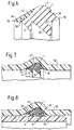
- Fig. 6 is an axial section corresponding to fig. 2 of a second type of sealing ring in which the element according to fig. 1 is included.
- Fig. 7 is an axial section of the sealing ring according to fig. 6 positioned in a groove in a pipe socket.
- Fig. 8 is a section corresponding to fig. 7 of a pipe joint in which a sealing ring according to the second embodiment is included.
- Fig. 9 is an axial section corresponding to fig. 1 of a modified embodiment of an annular element according to the invention.
- Figs. 10 and 11 are axial sections of two different types of sealing rings manufactured according to the method of the invention and by means of the element according to the invention shown in fig. 9.
- Fig. 12 is an axial section corresponding to figs. 1 and 9 of a further embodiment of an annular element according to the invention.
- Figs. 13 and 14 are axial sections of two different types of sealing rings manufactured according to the method of the invention and by means of the element according to the invention shown in fig. 12.
- the element 1 according to the invention shown in fig. 1 is of annular shape and is adapted to form a sealing element of a sealing ring for sealing a space in a pipe joint between two plastic pipes and preferably in a pipe joint between plastic pipes in which the pressure in the pipes is relatively high in relation to the pressure outside the pipes.
- the sealing ring is adapted to be mounted in an annular groove at the inner surface of a pipe socket into which the spigot end of another pipe is introduced for forming the pipe joint. Thereby, the sealing ring is adapted to be compressed between the bottom of the groove in the socket and the outer surface of the spigot end.
- the element 1 of the sealing ring which element is shown in fig. 1 consists of rubber, for example a rubber having a Shore-hardness of for example 40 - 50 o .
- the annular element 1 shown in fig. 1 is adapted to form a sealing element in a sealing ring.
- the element 1 has a surface portion 2 of a rounded shape and adapted to contact the bottom of the groove in the socket.
- the sealing element has an obliquely inwards directed lip 4.
- the lip forms a conical entering surface 6 which is initially engaged by the spigot end when the pipe joint is to be established by introducing the spigot end into the socket provided with the sealing ring.
- dirt which is present on the outer surface of the spigot end will be wiped off from the outer surface by the edge 8 of the lip.
- the sealing element has an obliquely inwards directed sealing projection 10.
- the sealing projection 10 has from its inner end initially a portion 12 having a constant thickness and merging into a portion 4 with reduced thickness.
- the sealing element 1 has between the surface portion 2 and the lip 4 a projecting edge portion 16. Between the surface portion 2 and the sealing projection 10 the sealing element 1 has an edge portion 18 projecting in the opposite direction in relation to the edge portion 16.
- the projecting edge portion 16 forms part of a binding surface 20 at one side of the sealing element 1, while the projecting edge portion 18 forms part of a binding surface 22 positioned at the other side of the sealing element 1.
- the binding surfaces 20 and 22 are positioned between the axial planes 24 and 26.
- the binding surface 20 forms a peripherally extending recess 28 having the object of increasing the area and efficiency of the binding surface.
- the binding surface 22 forms perpendicularly extending grooves 30 and a ridge 32 positioned between the grooves.
- the sealing element according to fig. 1 can be used for manufacturing two different types of sealing rings according to the method of the invention.
- the first type of sealing ring is shown in an axial section in fig. 2.
- the sealing ring has a retainer element 34 which is bound to the binding surface 22 of the sealing element 1.
- the binding surface 22 is not used for binding purposes.
- the sealing ring is manufactured by positioning the sealing element 1 in a mould space having a mould surface for forming the retainer element 34 in connection with the binding surface 22, whereupon a plastic material is injected into the mould space. The plastic material binds to the binding surface 22, and when the plastic material has been polymerized and the sealing ring has been removed from the mould it has the appearance as shown in fig. 2.
- the retainer element 34 has an outer conical surface 36 which connects with the surface portion 2 of the sealing element 1.
- the retainer element 34 has an obliquely inwards directed point 38 which is somewhat expandable in the radial direction.
- the retainer element 34 can be considered to be designed in accordance with the retainer portion of the sealing ring according to the US Patent No 4 818 209.
- the embodiment of the sealing ring shown in fig. 2 is intended to be used as a combined moulding and sealing ring, and in accordance therewith the ring is positioned in a shallow groove 40 on a mandrel 42 in accordance what is shown in fig. 3.
- An end portion of a thermoplastic material pipe softened by heating is pushed over the mandrel 42 and the sealing ring positioned thereon, while the ring is axially supported by a support cylinder 44.
- the support cylinder is withdrawn from the pipe end portion, whereby the pipe end portion will connect with the mandrel and the sealing ring while forming a groove for receiving the sealing ring.
- the mandrel is withdrawn from the pipe end portion, the sealing ring being left in the groove 47 formed in the socket 46.
- the socket 46 with the sealing ring positioned in the groove 47 therein has the appearance as shown in axial section in fig. 4.
- the sealing ring according to the embodiment of fig. 2 is shown included in a pipe joint for sealing the space between the pipe socket 46 and the spigot end 48 introduced therein.
- the lip 4 acts for wiping away dirt from the outer surface of the spigot end so that this in a cleaned condition arrives to the sealing projection 10.
- the projecting edge portion 16 forms a sealing lip which by engagement with the bottom of the groove 47 assists in preventing fluid from entering the pipe joint from outside the pipes.
- a sealing element 1 of the same kind as the sealing element of the sealing ring according to fig. 2 while the sealing ring has a retainer element 50 which is bound to the binding surface 20 of the sealing element 1.
- the binding surface 22 is not used for binding a retainer element to the sealing element.
- the retainer element 50 has an outer, conical surface 52 connecting with the surface portion 2 of the sealing element 1.
- the retainer element 50 has an edge portion 56 formed with a flat end surface 54.
- a pipe joint consisting of the pipe socket 58 shown in fig. 7 with the sealing ring positioned in the groove 57 therein and a spigot end 60 introduced into the socket.
- the lip 4 will at the introduction of the spigot end into the pipe socket wipe away dirt from the outer surface of the spigot end 60 for providing that the outer surface of the spigot end 60 will in a clean condition arrive to the sealing projection 10.
- the retainer element 50 will prevent the sealing ring from being blown out of the pipe joint.
- the manufacturing of the sealing ring according to figs. 6, 7 and 8 is conducted in the same way as the manufacturing of the sealing ring according to figs. 2 - 5, i.e. by positioning the sealing element 1 in a mould and injecting a plastic material into the mould space to be bound to the binding surface 20 of the sealing element 1.
- FIG. 9 there is shown a modified embodiment of an annular element 1a which is intended to form a sealing element in a sealing ring for sealing a space between a socket and a spigot end, the sealing ring being positioned in a groove formed in the socket.
- the element 1a At its radially outer surface the element 1a has a surface portion 2a of rounded shape adapted to engage the bottom of the groove in the socket.
- the surface portion 2a is provided with peripheral projections 62 for improving the sealing function in relation to the bottom of the groove.
- the sealing element 1a has an obliquely inwards directed sealing projection 10a of the same design as the sealing projection 10 of the annular element 1 according to fig. 1.
- the sealing projection 10a initially has a portion 12a of uniform thickness and thereupon has portion 14a having decreasing thickness.
- the sealing element 1a Between the surface portion 2a and the lip 10a the sealing element 1a has a flat edge portion 16a. Between the surface portion 2a and the sealing projection 10a the sealing element 1a also has an edge portion 18a projecting in the opposite direction in relation to the edge portion 16a.
- the edge portion 16a forms a flat binding surface 20a at one side of the sealing element 1a, while the projecting edge portion 18a forms part of a binding surface 22a positioned at the opposite side of the sealing element 1a.
- the binding surfaces 20a and 22a are positioned between the axial planes 24a and 26a.
- the binding surface 22a is of the same design as the binding surface 22 in the sealing element 1 according to fig. 1 and, thus, the binding surface 22a forms peripheral grooves 30a and an intermediate ridge 32a.
- the sealing element 1a according to fig. 9 is as shown in fig. 10 and 11 used for manufacturing two different types of sealing rings according to the method of the invention.
- the embodiment of the sealing ring shown in fig. 10 comprises a sealing element 1a according to fig. 9 and a retainer element 50a which is bound to the binding surface 20a of the sealing element 1a.
- the binding surface 22a is not used for binding a retainer element to the sealing ring.
- the retainer element 50a has an outer, conical surface 52a which connects with the surface portion 2a of the sealing element 1a and has like the retainer element 50 of the sealing ring according to fig. 6 an edge portion 56a having a flat end surface 54a.
- the sealing ring according to fig. 10 the sealing ring according to fig.
- the sealing ring 10 is manufactured by positioning the sealing element 1a in a mould space having a mould surface for forming the retainer element 50a in connection with the binding surface 20a, whereupon a plastic material is injected into the mould space.
- the plastic material binds to the binding surface 20a, and when the plastic material has polymerized and the sealing ring has been removed from the mould the sealing ring has the appearance shown in fig. 10.
- the sealing ring according to fig. 10 is positioned in a groove in a socket and is used for sealing a space between a socket and a spigot end according to the same principles as shown in figs. 7 and 8.
- a sealing ring comprising a sealing element 1a of the same design as the sealing element shown in fig. 9 and the sealing element included in the sealing ring according to fig. 10.
- the sealing ring according to fig. 11 has two retainer elements, and in this embodiment of the sealing ring both binding surfaces 20a and 22a of the sealing element 1a are used.
- the retainer element bound to the binding surface 20a is of the same design as the retainer element 50a of the sealing ring according to fig. 10, while the retainer element 34a bound to the binding surface 22a is of the same design as the retainer element 34 of the sealing ring according to fig. 2.
- 11 can be used for forming a pipe socket around the sealing ring according to the method which is shown in figs. 3 and 4 and additionally has the function of the sealing rings according to figs. 6 and 10 to prevent that the sealing ring is blown out from the pipe joint at high inner pressures in the pipes.
- the manufacturing of the sealing ring according to fig. 11 takes place in the same way as the manufacturing of the sealing rings previously described, i.e. by positioning the sealing element 1a in a mould space having a mould surface for forming the two retainer elements 50a and 34a in connection with the binding surfaces 20a and 22a, respectively, whereupon the plastic material is injected into the mould space.
- the plastic material binds to the binding surfaces 20a and 22a, and when the plastic material has polymerized the sealing ring can be removed from the mould.
- a further annular element 1b which is intended for forming sealing elements in two different embodiments of sealing rings according to figs. 13 and 14.
- the sealing element 1b and the sealing ring according to figs. 13 and 14 differ from the sealing element 1a according to fig. 9 and the sealing rings according to figs. 10 and 11 only with regard to the design of the binding surface 20b.
- this binding surface 20b has an annular, central projection 64 having the object of providing a better binding of the retainer element 50b and to reduce the width of the wall of the retainer element 50b so as to facilitate the polymerization of the retainer element 50b.
- corresponding parts of the sealing element 1b of fig. 12 and the sealing rings according to figs. 13 and 14 are provided the same reference numerals as in figs. 9 - 11 with the replacement of the letter "a" by the letter "b".
- sealing element 1a and 1b sealing rings which are provided only with the retainer element 34a and 34b and in which the binding surface 20a and 20b, respectively, is not used.
- the method according to the invention makes it possible to use one and the same sealing element 1a, 1b and 1c for manufacturing different types of sealing rings by using one or the other of the binding surfaces or both binding surfaces.
- sealing elements having more than two binding surfaces which are used in different combinations for manufacturing sealing rings of many different kinds.
Landscapes
- General Engineering & Computer Science (AREA)
- Engineering & Computer Science (AREA)
- Mechanical Engineering (AREA)
- Gasket Seals (AREA)
- Glass Compositions (AREA)
- Piezo-Electric Or Mechanical Vibrators, Or Delay Or Filter Circuits (AREA)
- Encapsulation Of And Coatings For Semiconductor Or Solid State Devices (AREA)
- Complex Calculations (AREA)
- Sealing Battery Cases Or Jackets (AREA)
- Luminescent Compositions (AREA)
- Joints With Sleeves (AREA)
- Joints With Pressure Members (AREA)
- Mechanical Sealing (AREA)
- Sealing Devices (AREA)
Applications Claiming Priority (2)
| Application Number | Priority Date | Filing Date | Title |
|---|---|---|---|
| SE9200764A SE505267C2 (sv) | 1992-03-10 | 1992-03-10 | Sätt att framställa åtminstone två olika slag av tätningsringar och tätningselement för användning vid genomförande av sättet |
| SE9200764 | 1992-03-10 |
Publications (2)
| Publication Number | Publication Date |
|---|---|
| EP0560104A1 true EP0560104A1 (de) | 1993-09-15 |
| EP0560104B1 EP0560104B1 (de) | 1998-07-29 |
Family
ID=20385600
Family Applications (1)
| Application Number | Title | Priority Date | Filing Date |
|---|---|---|---|
| EP93102733A Expired - Lifetime EP0560104B1 (de) | 1992-03-10 | 1993-02-22 | Herstellungsverfahren für Dichtringe |
Country Status (10)
| Country | Link |
|---|---|
| US (1) | US6277315B1 (de) |
| EP (1) | EP0560104B1 (de) |
| JP (1) | JPH062790A (de) |
| AT (1) | ATE169100T1 (de) |
| DE (1) | DE69319946T2 (de) |
| DK (1) | DK0560104T3 (de) |
| ES (1) | ES2118843T3 (de) |
| FI (1) | FI102408B (de) |
| NO (1) | NO306685B1 (de) |
| SE (1) | SE505267C2 (de) |
Cited By (6)
| Publication number | Priority date | Publication date | Assignee | Title |
|---|---|---|---|---|
| WO1999066248A1 (en) * | 1998-06-19 | 1999-12-23 | S & B Technical Products, Inc. | Pipe gasket with combined lip and compression seal geometries |
| EP1185809A1 (de) * | 1999-03-03 | 2002-03-13 | S & B Technical Products, Inc. | Doppelzweckdichtung mit geringer einsteckkraft |
| WO2007123459A1 (en) * | 2006-04-21 | 2007-11-01 | Trelleborg Forsheda Building Ab | Sealing ring |
| EP2413011A1 (de) * | 2010-07-30 | 2012-02-01 | Prabhat Elastomers Pvt Ltd. | Dichtung für das Muffenende eines Rohres |
| EP2426390A3 (de) * | 2010-09-03 | 2014-06-25 | Poloplast GmbH & Co. KG | Rohrendsteckmuffendichtungsanordnung |
| WO2019076453A1 (en) * | 2017-10-18 | 2019-04-25 | Trelleborg Pipe Seals Lelystad B.V. | PIPE SEAL, PIPE ASSEMBLY, AND METHOD OF FORMING SEALING JOINT |
Families Citing this family (17)
| Publication number | Priority date | Publication date | Assignee | Title |
|---|---|---|---|---|
| US6142325A (en) * | 1998-10-19 | 2000-11-07 | Playtex Products, Inc. | Container assembly and bottom cap therefor |
| JP4612965B2 (ja) * | 2001-06-06 | 2011-01-12 | 大日本プラスチックス株式会社 | パッキングリング |
| AT409945B (de) * | 2001-08-02 | 2002-12-27 | Schnallinger Helmuth | Verfahren zum herstellen einer rohrendmuffe aus thermoplastischem kunststoff |
| SE517982C2 (sv) * | 2001-09-27 | 2002-08-13 | Forsheda Ab | Tätningsring för rör, framställd genom samextrudering av ett mjukare och ett hårdare material |
| DE10219865B4 (de) * | 2002-05-03 | 2005-03-31 | M.O.L. Gummiverarbeitung Gmbh & Co. Kg | Dichtring für eine Steckmuffenverbindung |
| US7140618B2 (en) * | 2003-01-16 | 2006-11-28 | Vassallo Research & Development Corporation | Socket with dual-functional composite gasket |
| US7158034B2 (en) * | 2004-01-12 | 2007-01-02 | Corbett Jr Bradford G | Pipe gasket manufacturing and identification method with RFID tracking |
| EP1619435B1 (de) | 2004-07-20 | 2009-03-11 | Bode GmbH | Dichtring für Steckmuffenverbindungen |
| US7423216B2 (en) * | 2006-01-23 | 2008-09-09 | Watlow Electric Manufacturing Company | Dual action sealing gasket and use thereof in an electrical housing assembly |
| DE102007048119B4 (de) | 2007-10-05 | 2009-07-02 | M.O.L. Gummiverarbeitung Gmbh & Co. Kg | Dichtring für eine Steckmuffenverbindung zweier Rohre |
| US20090273184A1 (en) * | 2008-04-30 | 2009-11-05 | Michael Wright | Self restrained joint for ductile iron pipe and fittings |
| KR100904912B1 (ko) * | 2009-01-15 | 2009-06-29 | (주)프라텍 | 디씨 파이프 연결용 패킹 |
| DE102012019105A1 (de) * | 2012-09-28 | 2014-04-03 | Carl Freudenberg Kg | Steckstück |
| WO2015143345A1 (en) * | 2014-03-20 | 2015-09-24 | Griffin Pipe Products Co., Llc | Flexible pipe joint |
| DE202015103221U1 (de) * | 2015-06-18 | 2016-09-20 | Rehau Ag + Co | Rohr oder Rohrformteil |
| DE102016213899A1 (de) * | 2016-07-28 | 2018-02-01 | Mahle International Gmbh | Dichtungselement |
| US10876672B2 (en) * | 2017-02-24 | 2020-12-29 | S & B Technical Products, Inc. | Sealing joint for low pressure pipe systems and method of manufacture |
Citations (5)
| Publication number | Priority date | Publication date | Assignee | Title |
|---|---|---|---|---|
| DE1799534U (de) * | 1959-08-20 | 1959-11-05 | Halbergerhuette Ges Mit Beschr | Dichtung fuer muffenrohre. |
| FR2234508A1 (en) * | 1973-06-21 | 1975-01-17 | Bertschmann Hans | Flexible joining seal for tulip ended pipe - has three unequal section rings connected by flexible membranes |
| DE2364392A1 (de) * | 1973-12-22 | 1975-07-10 | Continental Gummi Werke Ag | Muffenrohrverbindung mit an der innenflaeche der muffe vorgesehener ringfoermiger dichtung |
| US4834398A (en) * | 1987-08-31 | 1989-05-30 | S & B Technical Products, Inc. | Pipe gasket |
| US5067751A (en) * | 1990-07-27 | 1991-11-26 | American Cast Iron Pipe Company | Gasket for field adaptable push-on restrained joint and joint thus produced |
Family Cites Families (14)
| Publication number | Priority date | Publication date | Assignee | Title |
|---|---|---|---|---|
| GB454900A (en) * | 1934-12-27 | 1936-10-09 | Buderus Eisenwerk | Improvements in or relating to resilient packings for socket pipes |
| DE667458C (de) * | 1936-11-27 | 1938-11-11 | Buderus Eisenwerk | Muffenrohrverbindung mit buechsenartigem Dichtungskoerper |
| DE1924410C3 (de) * | 1969-05-13 | 1975-10-02 | Eisenwerke Fried. Wilh. Dueker Gmbh & Co, 8782 Karlstadt | Muffenverbindung für Rohre |
| DE2135841A1 (de) * | 1971-07-17 | 1973-02-08 | Mueller Artur Fa | Muffenrohrsteckverbindung |
| DE2510234C2 (de) | 1974-03-15 | 1983-02-17 | Amiantus AG, Niederurnen | Dichtungsring für Rohrkupplungen |
| DE2623399C2 (de) | 1976-05-25 | 1982-12-30 | Industrie-Automation Gmbh & Co, 6900 Heidelberg | Afokaler Spektralwandler |
| JPS5312517A (en) * | 1976-07-21 | 1978-02-04 | Kubota Ltd | Structure for pipe socket made of synthetic resin |
| CH643047A5 (de) * | 1978-10-18 | 1984-05-15 | Battenfeld Maschfab | Verfahren zum herstellen von fittings fuer rohrverbindungen sowie werkzeug zur ausuebung des verfahrens und nach diesem verfahren hergestelltes fitting. |
| US4379559A (en) | 1979-06-29 | 1983-04-12 | Forsheda Gummifabrik Ab | Pipe sealing device |
| GB2092241B (en) * | 1981-01-30 | 1984-07-18 | Apv The Co Ltd | Gasket arrangement for plate heat exchanger |
| US4693483A (en) * | 1984-07-13 | 1987-09-15 | Vassallo Research & Development Corporation | Composite gasket and fitting including same |
| US4826028A (en) * | 1985-03-18 | 1989-05-02 | Vassallo Research & Development Corp. | Gasket seating ring |
| SE463664B (sv) | 1986-04-17 | 1991-01-07 | Forsheda Ab | Formnings- och taetningsring |
| SE8800348L (sv) * | 1988-02-03 | 1989-08-04 | Forsheda Ab | Taetningsring och verktyg foer framstaellning daerav |
-
1992
- 1992-03-10 SE SE9200764A patent/SE505267C2/sv not_active IP Right Cessation
-
1993
- 1993-02-22 AT AT93102733T patent/ATE169100T1/de not_active IP Right Cessation
- 1993-02-22 ES ES93102733T patent/ES2118843T3/es not_active Expired - Lifetime
- 1993-02-22 DK DK93102733T patent/DK0560104T3/da active
- 1993-02-22 DE DE69319946T patent/DE69319946T2/de not_active Expired - Lifetime
- 1993-02-22 EP EP93102733A patent/EP0560104B1/de not_active Expired - Lifetime
- 1993-03-02 JP JP5041229A patent/JPH062790A/ja active Pending
- 1993-03-08 FI FI931010A patent/FI102408B/fi active
- 1993-03-09 NO NO930866A patent/NO306685B1/no not_active IP Right Cessation
-
1995
- 1995-08-04 US US08/511,451 patent/US6277315B1/en not_active Expired - Lifetime
Patent Citations (5)
| Publication number | Priority date | Publication date | Assignee | Title |
|---|---|---|---|---|
| DE1799534U (de) * | 1959-08-20 | 1959-11-05 | Halbergerhuette Ges Mit Beschr | Dichtung fuer muffenrohre. |
| FR2234508A1 (en) * | 1973-06-21 | 1975-01-17 | Bertschmann Hans | Flexible joining seal for tulip ended pipe - has three unequal section rings connected by flexible membranes |
| DE2364392A1 (de) * | 1973-12-22 | 1975-07-10 | Continental Gummi Werke Ag | Muffenrohrverbindung mit an der innenflaeche der muffe vorgesehener ringfoermiger dichtung |
| US4834398A (en) * | 1987-08-31 | 1989-05-30 | S & B Technical Products, Inc. | Pipe gasket |
| US5067751A (en) * | 1990-07-27 | 1991-11-26 | American Cast Iron Pipe Company | Gasket for field adaptable push-on restrained joint and joint thus produced |
Cited By (9)
| Publication number | Priority date | Publication date | Assignee | Title |
|---|---|---|---|---|
| US6152494A (en) * | 1998-01-12 | 2000-11-28 | S&B Technical Products, Inc. | Pipe gasket with combined lip and compression seal geometries |
| WO1999066248A1 (en) * | 1998-06-19 | 1999-12-23 | S & B Technical Products, Inc. | Pipe gasket with combined lip and compression seal geometries |
| EP1185809A1 (de) * | 1999-03-03 | 2002-03-13 | S & B Technical Products, Inc. | Doppelzweckdichtung mit geringer einsteckkraft |
| EP1185809A4 (de) * | 1999-03-03 | 2005-01-19 | S & B Technical Products Inc | Doppelzweckdichtung mit geringer einsteckkraft |
| WO2007123459A1 (en) * | 2006-04-21 | 2007-11-01 | Trelleborg Forsheda Building Ab | Sealing ring |
| AU2007241584B2 (en) * | 2006-04-21 | 2013-07-18 | Trelleborg Forsheda Building Ab | Sealing ring |
| EP2413011A1 (de) * | 2010-07-30 | 2012-02-01 | Prabhat Elastomers Pvt Ltd. | Dichtung für das Muffenende eines Rohres |
| EP2426390A3 (de) * | 2010-09-03 | 2014-06-25 | Poloplast GmbH & Co. KG | Rohrendsteckmuffendichtungsanordnung |
| WO2019076453A1 (en) * | 2017-10-18 | 2019-04-25 | Trelleborg Pipe Seals Lelystad B.V. | PIPE SEAL, PIPE ASSEMBLY, AND METHOD OF FORMING SEALING JOINT |
Also Published As
| Publication number | Publication date |
|---|---|
| SE505267C2 (sv) | 1997-07-28 |
| EP0560104B1 (de) | 1998-07-29 |
| FI102408B1 (fi) | 1998-11-30 |
| DE69319946D1 (de) | 1998-09-03 |
| SE9200764L (sv) | 1993-09-11 |
| ATE169100T1 (de) | 1998-08-15 |
| JPH062790A (ja) | 1994-01-11 |
| US6277315B1 (en) | 2001-08-21 |
| NO306685B1 (no) | 1999-12-06 |
| DE69319946T2 (de) | 1998-12-10 |
| FI931010A (fi) | 1993-09-11 |
| AU666350B2 (en) | 1996-02-08 |
| SE9200764D0 (sv) | 1992-03-10 |
| FI102408B (fi) | 1998-11-30 |
| DK0560104T3 (da) | 1998-12-14 |
| FI931010A0 (fi) | 1993-03-08 |
| NO930866L (no) | 1993-09-13 |
| AU3396193A (en) | 1993-09-16 |
| ES2118843T3 (es) | 1998-10-01 |
| NO930866D0 (no) | 1993-03-09 |
Similar Documents
| Publication | Publication Date | Title |
|---|---|---|
| EP0560104B1 (de) | Herstellungsverfahren für Dichtringe | |
| US5064207A (en) | Sealing ring for sealing a pipe joint | |
| CA1291185C (en) | Mould and sealing ring | |
| AU672912B2 (en) | Plug-in socket joint secured against sliding movement | |
| CA1279077C (en) | Hose coupling | |
| US4779651A (en) | Plastic corrugated tube with integrally molded sleeve coupler | |
| US4969667A (en) | Hose coupling | |
| JP3427228B2 (ja) | 滑りを防止したプラグイン形スピゴット・ソケット継手 | |
| US5988704A (en) | Hose coupling device | |
| US6199915B1 (en) | Connector element for tubing or hoses | |
| EP0017300A1 (de) | Dichtungselement für eine Rohrverbindung | |
| EP0564990B1 (de) | Verbindung und/oder T-Verbindung für flexible Rohre | |
| US5672113A (en) | Cylindrical boot fixing portion of resin boot with annular exterior convex portion | |
| AU705827B2 (en) | Sockets serving for the connection of two plastic pipes and process for the production of such a socket | |
| US4458904A (en) | Seal for use with pipes to be fitted one into another with spigot and socket ends | |
| US20040140625A1 (en) | Socket with dual-functional composite gasket | |
| EP1041332A1 (de) | Rohrförmige Kunststoffverbindung mit einem Klemmring aus Kunststoff | |
| US20060049627A1 (en) | Pipe joint gasket | |
| US4372905A (en) | Method of forming a pipe socket | |
| US6193238B1 (en) | Sealing device | |
| US6089618A (en) | Sealing device for pipes | |
| US6076834A (en) | Sealing element | |
| EP0507005B1 (de) | Rohrverbindung | |
| EP1222418B1 (de) | Verbindungsstück | |
| EP0358256A1 (de) | Dichtung und Schutzvorrichtung für Rohre |
Legal Events
| Date | Code | Title | Description |
|---|---|---|---|
| PUAI | Public reference made under article 153(3) epc to a published international application that has entered the european phase |
Free format text: ORIGINAL CODE: 0009012 |
|
| AK | Designated contracting states |
Kind code of ref document: A1 Designated state(s): AT BE CH DE DK ES FR GB GR IE IT LI MC NL PT SE |
|
| RBV | Designated contracting states (corrected) |
Designated state(s): AT BE CH DE DK ES FR GB IT LI NL PT SE |
|
| 17P | Request for examination filed |
Effective date: 19940314 |
|
| 17Q | First examination report despatched |
Effective date: 19950328 |
|
| APAB | Appeal dossier modified |
Free format text: ORIGINAL CODE: EPIDOS NOAPE |
|
| APAD | Appeal reference recorded |
Free format text: ORIGINAL CODE: EPIDOS REFNE |
|
| APCB | Communication from the board of appeal sent |
Free format text: ORIGINAL CODE: EPIDOS OBAPE |
|
| APCB | Communication from the board of appeal sent |
Free format text: ORIGINAL CODE: EPIDOS OBAPE |
|
| APAB | Appeal dossier modified |
Free format text: ORIGINAL CODE: EPIDOS NOAPE |
|
| GRAG | Despatch of communication of intention to grant |
Free format text: ORIGINAL CODE: EPIDOS AGRA |
|
| GRAG | Despatch of communication of intention to grant |
Free format text: ORIGINAL CODE: EPIDOS AGRA |
|
| GRAG | Despatch of communication of intention to grant |
Free format text: ORIGINAL CODE: EPIDOS AGRA |
|
| GRAH | Despatch of communication of intention to grant a patent |
Free format text: ORIGINAL CODE: EPIDOS IGRA |
|
| GRAH | Despatch of communication of intention to grant a patent |
Free format text: ORIGINAL CODE: EPIDOS IGRA |
|
| GRAA | (expected) grant |
Free format text: ORIGINAL CODE: 0009210 |
|
| AK | Designated contracting states |
Kind code of ref document: B1 Designated state(s): AT BE CH DE DK ES FR GB IT LI NL PT SE |
|
| PG25 | Lapsed in a contracting state [announced via postgrant information from national office to epo] |
Ref country code: LI Free format text: LAPSE BECAUSE OF FAILURE TO SUBMIT A TRANSLATION OF THE DESCRIPTION OR TO PAY THE FEE WITHIN THE PRESCRIBED TIME-LIMIT Effective date: 19980729 Ref country code: CH Free format text: LAPSE BECAUSE OF FAILURE TO SUBMIT A TRANSLATION OF THE DESCRIPTION OR TO PAY THE FEE WITHIN THE PRESCRIBED TIME-LIMIT Effective date: 19980729 Ref country code: BE Free format text: LAPSE BECAUSE OF FAILURE TO SUBMIT A TRANSLATION OF THE DESCRIPTION OR TO PAY THE FEE WITHIN THE PRESCRIBED TIME-LIMIT Effective date: 19980729 Ref country code: AT Free format text: LAPSE BECAUSE OF FAILURE TO SUBMIT A TRANSLATION OF THE DESCRIPTION OR TO PAY THE FEE WITHIN THE PRESCRIBED TIME-LIMIT Effective date: 19980729 |
|
| REF | Corresponds to: |
Ref document number: 169100 Country of ref document: AT Date of ref document: 19980815 Kind code of ref document: T |
|
| REG | Reference to a national code |
Ref country code: CH Ref legal event code: EP |
|
| ET | Fr: translation filed | ||
| REF | Corresponds to: |
Ref document number: 69319946 Country of ref document: DE Date of ref document: 19980903 |
|
| REG | Reference to a national code |
Ref country code: ES Ref legal event code: FG2A Ref document number: 2118843 Country of ref document: ES Kind code of ref document: T3 |
|
| PG25 | Lapsed in a contracting state [announced via postgrant information from national office to epo] |
Ref country code: SE Free format text: LAPSE BECAUSE OF FAILURE TO SUBMIT A TRANSLATION OF THE DESCRIPTION OR TO PAY THE FEE WITHIN THE PRESCRIBED TIME-LIMIT Effective date: 19981029 |
|
| REG | Reference to a national code |
Ref country code: DK Ref legal event code: T3 |
|
| REG | Reference to a national code |
Ref country code: PT Ref legal event code: SC4A Free format text: AVAILABILITY OF NATIONAL TRANSLATION Effective date: 19981012 Ref country code: CH Ref legal event code: PL |
|
| PLBE | No opposition filed within time limit |
Free format text: ORIGINAL CODE: 0009261 |
|
| STAA | Information on the status of an ep patent application or granted ep patent |
Free format text: STATUS: NO OPPOSITION FILED WITHIN TIME LIMIT |
|
| 26N | No opposition filed | ||
| REG | Reference to a national code |
Ref country code: GB Ref legal event code: IF02 |
|
| PGFP | Annual fee paid to national office [announced via postgrant information from national office to epo] |
Ref country code: PT Payment date: 20050127 Year of fee payment: 13 |
|
| PGFP | Annual fee paid to national office [announced via postgrant information from national office to epo] |
Ref country code: DK Payment date: 20050203 Year of fee payment: 13 |
|
| PGFP | Annual fee paid to national office [announced via postgrant information from national office to epo] |
Ref country code: NL Payment date: 20050214 Year of fee payment: 13 |
|
| PGFP | Annual fee paid to national office [announced via postgrant information from national office to epo] |
Ref country code: ES Payment date: 20050217 Year of fee payment: 13 |
|
| APAH | Appeal reference modified |
Free format text: ORIGINAL CODE: EPIDOSCREFNO |
|
| PG25 | Lapsed in a contracting state [announced via postgrant information from national office to epo] |
Ref country code: ES Free format text: LAPSE BECAUSE OF NON-PAYMENT OF DUE FEES Effective date: 20060223 |
|
| PG25 | Lapsed in a contracting state [announced via postgrant information from national office to epo] |
Ref country code: DK Free format text: LAPSE BECAUSE OF NON-PAYMENT OF DUE FEES Effective date: 20060228 |
|
| PGFP | Annual fee paid to national office [announced via postgrant information from national office to epo] |
Ref country code: IT Payment date: 20060228 Year of fee payment: 14 |
|
| PG25 | Lapsed in a contracting state [announced via postgrant information from national office to epo] |
Ref country code: PT Free format text: LAPSE BECAUSE OF NON-PAYMENT OF DUE FEES Effective date: 20060822 |
|
| PG25 | Lapsed in a contracting state [announced via postgrant information from national office to epo] |
Ref country code: NL Free format text: LAPSE BECAUSE OF NON-PAYMENT OF DUE FEES Effective date: 20060901 |
|
| REG | Reference to a national code |
Ref country code: DK Ref legal event code: EBP |
|
| REG | Reference to a national code |
Ref country code: PT Ref legal event code: MM4A Effective date: 20060822 |
|
| NLV4 | Nl: lapsed or anulled due to non-payment of the annual fee |
Effective date: 20060901 |
|
| REG | Reference to a national code |
Ref country code: ES Ref legal event code: FD2A Effective date: 20060223 |
|
| PG25 | Lapsed in a contracting state [announced via postgrant information from national office to epo] |
Ref country code: IT Free format text: LAPSE BECAUSE OF NON-PAYMENT OF DUE FEES Effective date: 20070222 |
|
| PGFP | Annual fee paid to national office [announced via postgrant information from national office to epo] |
Ref country code: GB Payment date: 20100208 Year of fee payment: 18 Ref country code: DE Payment date: 20100204 Year of fee payment: 18 |
|
| GBPC | Gb: european patent ceased through non-payment of renewal fee |
Effective date: 20110222 |
|
| REG | Reference to a national code |
Ref country code: DE Ref legal event code: R119 Ref document number: 69319946 Country of ref document: DE Effective date: 20110901 |
|
| PG25 | Lapsed in a contracting state [announced via postgrant information from national office to epo] |
Ref country code: GB Free format text: LAPSE BECAUSE OF NON-PAYMENT OF DUE FEES Effective date: 20110222 |
|
| PGFP | Annual fee paid to national office [announced via postgrant information from national office to epo] |
Ref country code: FR Payment date: 20120228 Year of fee payment: 20 |
|
| PG25 | Lapsed in a contracting state [announced via postgrant information from national office to epo] |
Ref country code: DE Free format text: LAPSE BECAUSE OF NON-PAYMENT OF DUE FEES Effective date: 20110901 |