EP0558097A1 - Rammbohrgerät - Google Patents
Rammbohrgerät Download PDFInfo
- Publication number
- EP0558097A1 EP0558097A1 EP93106712A EP93106712A EP0558097A1 EP 0558097 A1 EP0558097 A1 EP 0558097A1 EP 93106712 A EP93106712 A EP 93106712A EP 93106712 A EP93106712 A EP 93106712A EP 0558097 A1 EP0558097 A1 EP 0558097A1
- Authority
- EP
- European Patent Office
- Prior art keywords
- boring machine
- ram boring
- machine according
- pistons
- tip
- Prior art date
- Legal status (The legal status is an assumption and is not a legal conclusion. Google has not performed a legal analysis and makes no representation as to the accuracy of the status listed.)
- Granted
Links
- 238000009527 percussion Methods 0.000 claims abstract description 12
- 230000006835 compression Effects 0.000 claims description 19
- 238000007906 compression Methods 0.000 claims description 19
- 230000008719 thickening Effects 0.000 claims description 6
- 239000012530 fluid Substances 0.000 description 8
- 238000005553 drilling Methods 0.000 description 4
- 230000002040 relaxant effect Effects 0.000 description 3
- 238000006073 displacement reaction Methods 0.000 description 2
- 230000007935 neutral effect Effects 0.000 description 2
- 239000002689 soil Substances 0.000 description 2
- 206010041953 Staring Diseases 0.000 description 1
- 238000006243 chemical reaction Methods 0.000 description 1
- 239000007788 liquid Substances 0.000 description 1
- XLYOFNOQVPJJNP-UHFFFAOYSA-N water Substances O XLYOFNOQVPJJNP-UHFFFAOYSA-N 0.000 description 1
Images


Classifications
-
- E—FIXED CONSTRUCTIONS
- E21—EARTH DRILLING; MINING
- E21B—EARTH DRILLING, e.g. DEEP DRILLING; OBTAINING OIL, GAS, WATER, SOLUBLE OR MELTABLE MATERIALS OR A SLURRY OF MINERALS FROM WELLS
- E21B4/00—Drives for drilling, used in the borehole
- E21B4/06—Down-hole impacting means, e.g. hammers
- E21B4/14—Fluid operated hammers
- E21B4/145—Fluid operated hammers of the self propelled-type, e.g. with a reverse mode to retract the device from the hole
-
- E—FIXED CONSTRUCTIONS
- E21—EARTH DRILLING; MINING
- E21B—EARTH DRILLING, e.g. DEEP DRILLING; OBTAINING OIL, GAS, WATER, SOLUBLE OR MELTABLE MATERIALS OR A SLURRY OF MINERALS FROM WELLS
- E21B7/00—Special methods or apparatus for drilling
- E21B7/04—Directional drilling
- E21B7/06—Deflecting the direction of boreholes
- E21B7/068—Deflecting the direction of boreholes drilled by a down-hole drilling motor
Definitions
- the invention relates to a pressure medium driven ram boring machine for earth bores with a striking tip arranged radially adjustable in the housing and acted upon by a percussion piston moved to and fro in a device housing.
- a hydraulic drilling ram The structure and function of a hydraulic drilling ram are described in German Patent No. 21 57 295.
- a ram boring machine primarily serves to lay supply lines, such as water pipes or cables under roads or dams or other buildings and obstacles, without having to rip open the road surface or the surface of the earth at the same time. This is done in such a way that the ram boring machine moving forward in the soil displaces the soil to the side and leaves a channel in which the supply line is drawn in simultaneously or later.
- the impact tip is used to smash stones and other obstacles and push them aside during the forward movement of the ram boring machine, i.e. to clear the way for the moving housing.
- a ram boring machine with a targeted running direction is known from DE-OS 22 42 605 and has at its rear end a tubular bent extension, which is also provided with curved guide surfaces in order to achieve an arcuate course of the earth bore in this way.
- Making such curved earth bores is necessary, for example, when there is no way to dig start and target pits in narrow streets with narrow sidewalks, which have to be at least so deep that the ram boring machine can be placed horizontally in the starting pit and all below lines lying under the road surface.
- the rigid baffles therefore serve to enable an arcuate course of the earth bore that is already intended before the device is attached; the direction cannot be influenced during operation.
- British Patent Specification 1 303 547 describes a pressure-driven ram boring machine for earth bores with an impact tip acted upon by a percussion piston moved to and fro in the device housing, which is enveloped by a jacket tube at a distance and is radially adjustable relative to the jacket tube by means of actuating means that can optionally be subjected to pressure medium, by the direction of advance to influence or correct the ram boring machine during operation.
- the tip of the drill can be adjusted radially by means of controlled adjustable adjusting elements.
- the propulsion is not generated by a ram drilling machine operated by pressure medium, but by striking the end of a pipe connected to the tip.
- the invention has for its object to provide a ram boring machine with which targeted changes in direction can be carried out.
- the impact tip which can either be arranged in the housing in a longitudinally movable manner or rigidly connected to the housing, can be adjusted as desired from its usually central position in the housing in the case of a course deviating from the straight direction of advance either in a horizontal or vertical plane, and thus the Counteract the directional deviation accordingly.
- Deviations in direction can be registered, for example, by a measuring sensor arranged on the ram boring machine and read by an operator on a remote control panel. If the direction changes, the operator can initiate the appropriate correction from the control panel, for example via hydraulic or pneumatic pressure lines connected to the impact tip.
- a plurality of actuating pistons can be provided in a radial plane around the pin of the percussion tip.
- three pistons which can be acted upon independently of one another can advantageously be arranged circumferentially distributed and connected to supply connections via pressure lines arranged in the housing of the ram boring machine. While the piston of one pump is pressurized, e.g. presses against the peg with a shell and moves the tip out of its central position, the pistons of the other pumps move accordingly into the pump housing or into the cylinder space, i.e. the pin or the percussion tip is positioned by means of coordinated adjusting movements of the piston pumps.
- a compression spring interacting unlockable locking sleeve which surrounds a centering ring of the pin of the hammer tip in the central position of the hammer tip, can ensure straight running of the ram boring machine in the depressurized state of the pistons, ie the hammer tip is fixed during normal operation in its central position, from which it is only desired changes in direction can be adjusted, which requires the previous unlocking of the locking sleeve against the force of the compression spring.
- the locking sleeve can be removed from its seat enclosing the centering ring by supplying a pressure medium, such as, in particular, hydraulic fluid, into a cylinder space receiving the locking sleeve.
- the locking sleeve can advantageously be designed as an axially movable control slide which has an axial central bore in an extension pin which can be acted upon by a pressure medium and, according to the number of pistons to be supplied, has radial distributor bores which can be connected to control lines of the pistons.
- all the pistons can be supplied with hydraulic fluid by means of only one pressure line led from the rear end through the housing of the ram boring machine; because the control slide is pushed axially depending on the adjustable pressure acting on the extension pin acting as a piston until a flow connection is established that connects the central bore with the radial distributor bore and the control line of the driven piston.
- the radial distributor bores are arranged axially spaced apart circumferentially from one another in the extension pin.
- axially displaceable actuating pistons with oblique piston surfaces on corresponding, oppositely inclined oblique surfaces can end of the pin of the impact tip.
- the radial adjustment of the impact tip is achieved by moving at least one piston in the direction opposite to the displacement direction of the other pistons, i.e. all pistons are moved from their starting position defined by the central position of the impact tip, but at least one piston in a different direction than the other pistons. Any radial adjustments can be carried out by means of the inclined plane defined by the corresponding inclined surfaces.
- the actuating pistons can be supported against compression springs, which are advantageously arranged in recesses in a centering shell that positively engages a spherical thickening of the pin.
- compression springs keep the percussion tip in its central position, the spring force corresponding to the pressure applied to the pistons, i.e. the pistons are clamped between the spring column and the liquid column.
- one piston is loaded with a pressure that exceeds the spring force, while the other actuating pistons are depressurized.
- the depressurized actuating pistons are moved from their initial position by the relaxing compression springs against the direction of the actuating piston which is subjected to higher pressure. After correcting the direction, all pistons are loaded with the same pressure corresponding to the spring force. The compressed spring then relaxes while the relaxed springs are compressed to the initial position of the pistons; the springs return the pistons to their original position.
- pneumatically inflatable rubber bellows can preferably be arranged in a radial plane around the pin of the impact tip. The when the rubber bellows which are supported in the housing of the ram boring machine are inflated, the reaction force exerts a movement which displaces the striking tip from its central position.
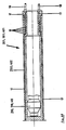
- a ram boring machine 201 is shown with a longitudinally movable striking tip 204 provided with a step head 203.
- the striking tip 204 of the ram boring machine 201 is held in the central position by a locking sleeve 20 during normal operation, that is to say during the straight running of the ram boring machine 201.
- a compression spring 21 pushes the locking sleeve 20, which is axially displaceable in a cylinder space 22, via a centering ring 23 arranged on the end of the pin 5 of the impact tip 204 facing away from the collar 206.
- three actuating pistons 24, 25, 26 are arranged in a radial plane (Fig. 2), the cylinder spaces 27 via pressure lines 17 with the at the rear end of The ram boring machine 201 arranged supply connections 18 (see FIG. 11) are connected.
- the hydraulic fluid supplied via a hydraulic line (not shown) is applied to the cylinder space 22 and the locking sleeve 20 is pushed against the force of the compression spring 21 by the centering ring 23 .
- Subsequent action on one of the actuating pistons 24 to 26 moves the percussion tip 204 into the desired eccentric position; corresponding to the eccentric position of the striking tip 204 shown in FIG. 3, the actuating piston 24 acts on the pin 205 and thus the striking tip 204 with a greater force than the actuating pistons 25, 26.
- the actuating pistons 25, 26 can optionally be completely depressurized, the hydraulic fluid running out of the cylinder spaces 27 via return lines, not shown.
- the cylinder space 22 of the locking sleeve 20 is relieved, so that the compression spring 21, which then relaxes, pushes the locking sleeve 20 onto the centering ring 23 and fixes the center position of the impact tip 204.
- Both the centering ring 23 and the locking sleeve 20 have sloping guide surfaces 28 and 29 that support the pushing on of the locking sleeve 20.
- the locking sleeve 20 that fixes the striking tip 204 in the central position allows the actuating pistons 24 to 26 to be depressurized during the locking, i.e. pressure only acts on the actuating pistons when the direction changes.
- the ram boring machine 301 with a rigid, ie not longitudinally movable impact tip 304 according to FIGS. 4 to 7 has actuating pistons 324, 325, 326 and also arranged in a radial plane around a pin 305 of the impact tip 304 a locking sleeve 320 designed as a control slide 30.
- the locking sleeve 320 of the control slide 30 receives in a cavity 31 a compression spring 321 which, in the central position shown in FIG. 4, also has a freely movable limiting disk 32 arranged in the cavity 31 in contact with a tapering one Mouthpiece 33 of the locking sleeve 320 holds.
- the mouthpiece 33 engages around a centering ring 323, which is located on the end of the pin 305 of the striking tip 304 facing away from the spherical thickening 316.
- the locking sleeve 320 continues on the side facing away from the mouthpiece 33 as an extension pin 34 which projects into a cylinder space 36 connected via a pressure line 35 to a pressure medium source (not shown).
- the extension pin 34 is provided with an axial central bore 37 and radial, circumferentially distributed, axially spaced distributor bores 38.
- a control line 39 leads from each cylinder space 327 of the actuating pistons 324, 325, 326 to the extension pin 34 of the control slide 30.
- the control lines 39 of which only the control lines 39 associated with the actuating pistons 324 and 326 are shown in the longitudinal sections according to FIGS. 4 and 6 can optionally be connected to the radial distributor bores 38 of the extension pin 34.
- the pressure-free line 35 according to FIG. 4 is first subjected to a pressure P0, whereupon the compression spring 321 is compressed and the control slide 30 is moved in the direction of arrow 40.
- the mouthpiece 33 of the locking sleeve 320 slides over the centering ring 323 of the pin 305 of the striking tip 304, ie the centering ring 323, together with the limiting disk 32, penetrates relatively further into the cavity 31 of the locking sleeve 320; which is a pretense the striking tip 304 from the central position preventing the seat of the locking sleeve 320 and the centering ring 323 is removed.
- the pressure P 1 prevails in the cylinder space 36, ie there is a flow connection between the pressure line 35 and the control line 39 associated with the control piston 324 and a flow connection between the pressure line 35 and the cylinder space 327 of the control piston 324.
- the Actuating piston 324 pressurized places the striking tip 304 in the ball joint defined by the spherical thickening 316 in the desired eccentric position. After the direction correction, the pressure line 35 is depressurized; the then relaxing compression spring 321 moves the control slide 30 against the direction of arrow 40 back into its starting position shown in FIG.
- any number of actuating pistons can pass through the housing 302 via only one from the rear end of the ram boring machine 301 pressure line 35 guided up to the cylinder space 36 of the control slide 30 are supplied; it also only requires a return line.
- actuating pistons 41, 42, 43 are arranged in a radial plane around the end of the pin 405 of the impact tip 404 lying inside the ram drilling device 401.
- the actuating pistons 41, 42, 43 lie with oblique piston surfaces 44 of radial piston projections 45 on corresponding, oppositely inclined oblique surfaces 46 of the inner end 47 of the pin 405.
- the actuating pistons 41, 42, 43 are held in the neutral position, shown in FIG. 8, of the striking tip 404 by the pressure fluid supplied via the pressure lines 17 (cf. FIG. 11) into the cylinder spaces 48 and by pressure springs 49.
- the compression springs 49 are arranged in recesses 50 of a centering shell 51 which surrounds approximately half of the outer surface of the spherical thickening 416 of the impact tip 404; the ball joint bearing is completed by correspondingly shaped inner surfaces of the stepped head 403, which encloses the other half of the spherical thickening 416 with inner shell surfaces.
- the cylinder space 48 of the actuating piston 41 is acted upon by a pressure which overcomes the force of the compression spring 49, so that the compression spring 49 which supports the actuating piston 41 is compressed.
- the pressure in the cylinder chambers 49 of the actuating pistons 42, 43 is simultaneously reduced to a value below the force of the compression springs 49 assigned to the actuating pistons 42, 43.
- the adjusting piston 41 moves in the direction of the arrow 52 and the adjusting pistons 42, 43 according to the arrow 53 in the opposite direction.
- the striking tip 404 is adjusted to the eccentric position according to FIG. 10.
- the pressure in the cylinder space 48 of the actuating piston 41 is reduced and the pressure in the cylinder spaces 48 of the actuating piston 42, 43 is increased.
- the adjusting piston 41 is advanced by the relaxing compression spring 49 against the direction of the arrow 52 and at the same time the compression springs 49 assigned to the adjusting pistons 42, 43 are pressed together by the advancing adjusting pistons 42, 43 against the direction of the arrow 53 until the neutral starting position according to FIG. 8 is reached is.
Abstract
Description
- Die Erfindung betrifft ein druckmittelbetriebenes Rammbohrgerät für Erdbohrungen mit einer von einem in einem Gerätegehäuse hin- und herbewegten Schlagkolben beaufschlagten radial verstellbar im Gehäuse angeordneten Schlagspitze.
- Der Aufbau und die Funktion eines druckmittelbetriebenen Rammbohrgeräts sind in der deutschen Patentschrift 21 57 295 beschrieben. Ein derartiges Rammbohrgerät dient in erster Linie dazu, Versorgungsleitungen, wie beispielsweise Wasserleitungen oder Kabel unter Straßen oder Dämmen oder sonstigen Gebäuden und Hindernissen zu verlegen, ohne daß gleichzeitig die Straßendecke bzw. die Erd-Oberfläche aufgerissen werden muß. Dies geschieht in der Weise, daß das sich im Erdreich vorwärtsbewegende Rammbohrgerät das Erdreich nach der Seite verdrängt und einen Kanal hinterläßt, in dem gleichzeitig oder später die Versorgungsleitung eingezogen wird. Die Schlagspitze dient dazu, während der Vorwärtsbewegung des Rammbohrgerätes Steine oder andere Hindernisse zu zertrümmern und zur Seite zu drücken, d.h. den Weg für das nachrückende Gehäuse freizuschlagen. Jedoch läßt es sich nicht immer vermeiden, daß das Rammbohrgerät beim Treffen auf ein Hindernis aus der gewollten Richtung läuft.
- Ein Rammbohrgerät mit gezielter Laufrichtung ist aus der DE-OS 22 42 605 bekannt und weist an seinem rückwärtigen Ende eine rohrförmig gebogene Verlängerung auf, die ebenfalls mit gebogenen Leitflächen versehen ist, um auf diese Weise einen bogenförmigen Verlauf der Erdbohrung zu erreichen. Derartige bogenförmig verlaufende Erdbohrungen herzustellen ist beispielsweise dann erforderlich, wenn in engen Straßen mit schmalen Bürgersteigen keine Möglichkeit besteht, Start- und Zielgruben auszuheben, die wenigstens so tief sein müssen, daß das Rammbohrgerät in der Startgrube waagerecht angesetzt werden kann und dabei noch sämtliche, unterhalb der Straßendecke liegende Leitungen unterfährt. Die starren Leitflächen dienen folglich dazu, einen bereits vor dem Ansetzen des Gerätes beabsichtigten bogenförmigen Verlauf der Erdbohrung zu ermöglichen; während des Betriebes läßt sich die Richtung nicht beeinflussen.
- In der britischen Patentschrift 1 303 547 ist ein druckmittelbetriebenes Rammbohrgerät für Erdbohrungen mit einer von einem im Gerätegehäuse hin- und herbewegten Schlagkolben beaufschlagten Schlagspitze beschrieben, das von einem Mantelrohr mit Abstand umhüllt und gegenüber dem Mantelrohr mittels wahlweise druckmittelbeaufschlagbarer Stellmittel radial verstellbar ist, um die Vorschubrichtung des Rammbohrgeräts während des Betriebes zu beeinflussen bzw. zu korrigieren.
- Bei einem aus der belgischen Patentschrift 865 955 bekannten Bohrgerät mit einer Schlagspitze läßt sich mittels gesteuert verstellbarer Stellelemente die Spitze des Bohrgeräts radial verstellen. Bei diesem Bohrgerät wird der Vortrieb nicht durch ein druckmittelbetriebenes Rammbohrgerät erzeugt, sondern durch Schläge auf das Ende eines mit der Spitze verbundenen Rohres.
- Der Erfindung liegt die Aufgabe zugrunde, ein Rammbohrgerät zu schaffen, mit dem sich gezielte Richtungsänderungen durchführen lassen.
- Diese Aufgabe wird erfindungsgemäß durch mehrere in einer Radialebene um einen Zapfen der Schlagspitze herum angeordnete Stellelemente gelöst. Bedingt durch die radiale Verstellbarkeit läßt sich die Schlagspitze, die entweder längsbeweglich im Gehäuse angeordnet oder starr mit dem Gehäuse verbunden sein kann, bei von der geraden Vortriebsrichtung entweder in horizontaler oder vertikaler Ebene abweichendem Verlauf aus ihrer üblicherweise zentrischen Lage im Gehäuse beliebig verstellen und damit der Richtungsabweichung entsprechend entgegenwirken. Richtungsabweichungen lassen sich beispielsweise durch einen am Rammbohrgerät angeordneten Meßaufnehmer registrieren und auf einem entfernten Schaltpult von einer Bedienungsperson ablesen. Bei Richtungsänderungen kann die Bedienungsperson die entsprechende Korrektur vom Schaltpult aus veranlassen, beispielsweise über hydraulische oder pneumatische, an die Schlagspitze angeschlossene Druckleitungen.
- Zum Verstellen der Schlagspitze aus ihrer Mittellage lassen sich gemäß einer bevorzugten Ausführung mehrere in einer Radialebene um den Zapfen der Schlagspitze herum angeordnete Stellkolben vorsehen. Hierbei lassen sich vorteilhaft drei unabhängig voneinander beaufschlagbare Kolben umfangsverteilt anordnen und über im Gehäuse des Rammbohrgerätes angeordnete Druckleitungen mit Versorgungsanschlüssen verbinden. Während der Kolben der einen Pumpe beaufschlagt wird, dabei z.B. mit einer Schale gegen den Zapfen drückt und die Spitze aus ihrer Mittellage bewegt, fahren die Kolben der anderen Pumpen entsprechend in das Pumpengehause bzw. in den Zylinderraum hinein, d.h. der Zapfen bzw. die Schlagspitze wird mittels koordinierter Stellbewegungen der Kolbenpumpen positioniert.
- Bei einer vorteilhaft mit einer Druckfeder zusammenwirkenden entriegelbaren Arretierhülse, die in der Mittellage der Schlagspitze einen Zentrierring des Zapfens der Schlagspitze umschließt, läßt sich ein Geradeauslauf des Rammbohrgerätes im drucklosen Zustand der Kolben gewährleisten, d.h. die Schlagspitze liegt während des normalen Betriebes in ihrer Mittellage fest, aus der sie sich nur bei gewünschten Richtungsänderungen verstellen läßt, was das vorherige Entriegeln der Arretierhülse gegen die Kraft der Druckfeder voraussetzt. Die Arretierhülse läßt sich von ihren den Zentrierring umschließenden Sitz durch Zuführen eines Druckmittels, wie insbesondere Hydraulikflüssigkeit, in einen die Arretierhülse aufnehmenden Zylinderraum entfernen.
- Die Arretierhülse läßt sich vorteilhaft als axial beweglicher Steuerschieber ausbilden, der in einem mittels eines Druckmittels beaufschlagbaren Verlängerungszapfen eine axiale Zentralbohrung und entsprechend der Anzahl der zu versorgenden Kolben radiale Verteilerbohrungen aufweist, die an Steuerleitungen der Kolben anschließbar sind. In diesem Fall lassen sich sämtliche Kolben mittels lediglich einer vom rückwärtigen Ende durch das Gehäuse des Rammbohrgerätes geführten Druckleitung mit Hydraulikflüssigkeit speisen; denn der Steuerschieber wird abhängig von dem einstellbaren, auf dem als Kolben wirkenden Verlängerungszapfen anstehenden Druck axial soweit vorgeschoben, bis eine Strömungsverbindung hergestellt ist, die die Zentralbohrung mit der radialen Verteilerbohrung und der Steuerleitung des angesteuerten Kolbens verbindet. Die radialen Verteilerbohrungen sind axial mit Abstand voneinander umfangsverteilt im Verlängerungszapfen angeordnet.
- Bei einer anderen Lösung können axial verschiebbare Stellkolben mit schrägen Kolbenflächen an korrespondierenden, entgegengesetzt geneigten Schrägflächen am Ende des Zapfens der Schlagspitze anliegen. Das radiale Verstellen der Schlagspitze wird hierbei durch Verschieben mindestens eines Kolbens in die der Verschieberichtung der anderen Kolben entgegengesetzte Richtung erreicht, d.h. alle Kolben werden aus ihrer durch die Mittellage der Schlagspitze definierten Ausgangsposition bewegt, jedoch zumindest ein Kolben in anderer Richtung als die anderen Kolben. Mittels der von den korrespondierenden Schrägflächen definierten schiefen Ebene lassen sich beliebige radiale Verstellungen durchführen.
- Die Stellkolben können sich gegen Druckfedern abstützen, die vorteilhaft in Ausnehmungen einer einer kugelförmigen Verdickung des Zapfens formschlüssig anliegenden Zentrierschale angeordnet sind. Während des Normalbetriebs des Rammbohrgerätes, d.h. solange keine Richtungsänderungen erforderlich sind, halten die Druckfedern die Schlagspitze in ihrer Mittellage, wobei die Federkraft dem auf die Kolben anstehenden Druck entspricht, d.h. die Kolben sind zwischen der Federsäule und der Flüssigkeitssäule eingespannt. Beim Verstellen der Schlagspitze aus der Mittellage wird der eine Kolben mit einem die Federkraft übersteigenden Druck belastet, während die anderen Stellkolben drucklos sind. Die drucklosen Stellkolben werden von den sich entspannenden Druckfedern entgegen der Richtung des mit höherem Druck beaufschlagten Stellkolbens aus ihrer Ausgangslage bewegt. Nach der Richtungskorrektur werden sämtliche Kolben mit demselben, der Federkraft entsprechenden Druck belastet. Die zusammengepreßte Feder entspannt sich dann, während die entspannten Federn bis zur Ausgangslage der Kolben zusammengedrückt werden; die Federn führen die Kolben in ihre Ausgangslage zurück.
- Gemäß einer weiteren Ausführung können in einer Radialebene um den Zapfen der Schlagspitze herum vorzugsweise pneumatisch aufblasbare Gummibälge angeordnet sein. Die beim Aufblasen der sich in dem Gehäuse des Rammbohrgerätes abstützenden Gummibälge bewirkte Reaktionskraft übt eine die Schlagspitze aus ihrer Mittellage verstellende Bewegung aus.
- Die Erfindung wird nachfolgend anhand mehrerer in den Zeichnungen dargestellter Ausführungsbeispiele des näheren erläutert. In den Zeichnungen zeigen:
- Fig. 1
- im Längsschnitt das vordere Ende eines eine längsbewegliche Schlagspitze mit Stufenkopf aufweisenden Rammbohrgerätes und erfindungsgemäß radial um einen Zapfen der Schlagspitze herum angeordnete Stellkolben, entlang der Linie VI-VI von Fig. 2 geschnitten,
- Fig. 2
- das Rammbohrgerät gemäß Fig. 1 entlang der Linie VII-VII von Fig. 1 geschnitten,
- Fig. 3
- das Rammbohrgerät gemäß Fig. 1 mit aus der Mittellage verstellter Schlagspitze,
- Fig. 4
- im Längsschnitt das vordere Ende eines Rammbohrgerätes mit einem starren, d.h. mit dem Gehäuse einstückigen Stufenkopf und darin angeordneter Schlagspitze, die am Ende eines in das Gehäuse ragenden Zapfens einen von einer als Steuerschieber ausgebildeten Arretierhülse umschlossenen Zentrierring aufweist,
- Fig. 5
- das Rammbohrgerät gemäß Fig. 4 entlang der Linie X-X von Fig. 4 geschnitten,
- Fig. 6
- das Rammbohrgerät gemäß Fig. 4 mit aus der Mittellage verstellter Schlagspitze,
- Fig. 7
- das Rammbohrgerät gemäß Fig. 6 entlang der Linie XII-XII von Fig. 6 geschnitten,
- Fig. 8
- das vordere Ende eines Rammbohrgerätes mit starrem Stufenkopf und darin angeordneter Schlagspitze, die am Ende eines in das Gehäuse ragenden Zapfens schräge Flächen besitzt, die mit Schrägflächen axial beweglicher Stellkolben korrespondieren, entlang der Linie XIII-XIII von Fig. 9 geschnitten,
- Fig. 9
- das Rammbohrgerät gemäß Fig. 8 entlang der Linie XIV-XIV von Fig. 8 geschnitten,
- Fig. 10
- das Rammbohrgerät gemäß Fig. 8 mit aus der Mittellage verstellter Schlagspitze,
- Fig. 11
- im Längsschnitt das rückwärtige Ende eines ein Rammbohrgerät aufnehmenden Mantelrohres mit Anschlüssen sowie Druckleitungen zum Zuführen des die Verstellbewegungen des nicht dargestellten Rammbohrgerätes bewirkenden Druckmediums.
- In den Fig. 1 bis 3 ist ein Rammbohrgerät 201 mit einer längsbeweglichen, mit einem Stufenkopf 203 versehenen Schlagspitze 204 dargestellt. Die Schlagspitze 204 des Rammbohrgerätes 201 wird während des Normalbetriebs, d.h. während des Geradeauslaufs des Rammbohrgerätes 201 von einer Arretierhülse 20 in der Mittellage gehalten. Dazu schiebt eine Druckfeder 21 die in einem Zylinderraum 22 axial verschiebliche Arretierhülse 20 über einen an dem dem Bund 206 abgewandten Ende des Zapfens 5 der Schlagspitze 204 angeordneten Zentrierring 23. Um den Zapfen 205 herum sind in einer Radialebene drei Stellkolben 24, 25, 26 angeordnet (Fig. 2), deren Zylinderräume 27 über Druckleitungen 17 mit den am rückwärtigen Ende des Rammbohrgerätes 201 angeordneten Versorgungsanschlüssen 18 (vgl. Fig. 11) verbunden sind.
- Zum radialen Verstellen der Schlagspitze 204 aus ihrer Mittellage gemäß Fig. 1 in die in Fig. 3 dargestellte außermittige Position wird der Zylinderraum 22 mit über eine nicht dargestellte Hydraulikleitung zugeführte Hydraulikflüssigkeit beaufschlagt und die Arretierhülse 20 gegen die Kraft der Druckfeder 21 von dem Zentrierring 23 geschoben. Durch anschließendes Beaufschlagen einer der Stellkolben 24 bis 26 verstellt sich die Schlagspitze 204 in die gewünschte außermittige Lage; entsprechend der in Fig. 3 dargestellten außermittigen Position der Schlagspitze 204 wirkt der Stellkolben 24 mit einer größeren Kraft als die Stellkolben 25, 26 auf den Zapfen 205 und damit die Schlagspitze 204 ein. Die Stellkolben 25, 26 können ggf. völlig drucklos sein, wobei die Hydraulikflüssigkeit aus den Zylinderräumen 27 über nicht dargestellte Rückleitungen abläuft. Nach der Richtungskorrektur wird der Zylinderraum 22 der Arretierhülse 20 entlastet, so daß die sich daraufhin entspannende Druckfeder 21 die Arretierhülse 20 auf den zentrierring 23 schiebt und die Mittellage der Schlagspitze 204 festlegt. Sowohl der Zentrierring 23 als auch die Arretierhülse 20 besitzen das Aufschieben der Arretierhülse 20 unterstützende schräge Führungsflächen 28 bzw. 29. Die die Schlagspitze 204 in der Mittellage festlegende Arretierhülse 20 erlaubt es, daß die Stellkolben 24 bis 26 während der Arretierung drucklos sein können, d.h. auf die Stellkolben wirkt ein Druck lediglich bei Richtungsänderungen ein.
- Das Rammbohrgerät 301 mit starrer, d.h. nicht längsbeweglicher Schlagspitze 304 gemäß den Fig. 4 bis 7 besitzt in einer Radialebene um einen Zapfen 305 der Schlagspitze 304 herum angeordnete Stellkolben 324, 325, 326 sowie eine als Steuerschieber 30 ausgebildete Arretierhülse 320. Die Arretierhülse 320 des Steuerschiebers 30 nimmt in einem Hohlraum 31 eine Druckfeder 321 auf, die in der in Fig. 4 dargestellten Mittellage eine außerdem in dem Hohlraum 31 angeordnete, freibewegliche Begrenzungsscheibe 32 in Anlage an ein sich verjüngendes Mundstück 33 der Arretierhülse 320 hält. Das Mundstück 33 umgreift in dieser Position einen Zentrierring 323, der sich an dem der kugelförmigen Verdickung 316 abgewandten Ende des Zapfen 305 der Schlagspitze 304 befindet. Die Arretierhülse 320 setzt sich an der dem Mundstück 33 abgewandten Seite als Verlängerungszapfen 34 fort, der in einen über eine Druckleitung 35 mit einer nicht dargestellten Druckmittelquelle verbundenen Zylinderraum 36 ragt. Der Verlängerungszapfen 34 ist mit einer axialen Zentralbohrung 37 sowie radialen, umfangsverteilten, axial einen Abstand voneinander aufweisenden Verteilerbohrungen 38 versehen. Von jedem Zylinderraum 327 der Stellkolben 324, 325, 326 führt eine Steuerleitung 39 zu dem Verlängerungszapfen 34 des Steuerschiebers 30. Die Steuerleitungen 39, von denen in den Längsschnitten gemäß den Fig. 4 und 6 lediglich die den Stellkolben 324 und 326 zugehörigen Steuerleitungen 39 dargestellt sind, lassen sich wahlweise mit den radialen Verteilerbohrungen 38 des Verlängerungszapfens 34 verbinden.
- Zum Verstellen der Schlagspitze 304 in die in Fig. 6 dargestellte außermittige Position wird die gemäß Fig. 4 drucklose Leitung 35 zunächst mit einem Druck P₀ beaufschlagt, worauf die Druckfeder 321 zusammengepreßt und der Steuerschieber 30 in Pfeilrichtung 40 verschoben wird. Das Mundstück 33 der Arretierhülse 320 schiebt sich dabei über den Zentrierring 323 des Zapfens 305 der Schlagspitze 304 hinweg, d.h. der Zentrierring 323 dringt zusammen mit der Begrenzungsscheibe 32 relativ weiter in den Hohlraum 31 der Arretierhülse 320 ein; der ein Verstellen der Schlagspitze 304 aus der Mittellage verhindernde Sitz von Arretierhülse 320 und Zentrierring 323 wird aufgehoben. Durch Erhöhen des Druckes in der Leitung 35 auf den Betrag P₁ rückt der Steuerschieber 30 in Pfeilrichtung 40 weiter vor, bis die Steuerleitung 39 des Stellkolbens 324 mit der dem Kolben 324 zugeordneten radialen Bohrung 38 verbunden ist. Die Druckflüssigkeit strömt dann aus der Zentralbohrung 37 des Verlängerungszapfens 34 über die Verteilerbohrung 38 und die Steuerleitung 39 in den Druckraum 327 des Stellkolbens 324. Durch Erhöhen des Druckes der über die Leitung 35 zugeführten Druckflüssigkeit auf den Betrag P₂, P₃, ... Pn lassen sich durch entsprechende Lageänderungen des Steuerschiebers 30 Steuerleitungen 39 beliebiger Stellkolben an den Druckflüssigkeitsstrom anschließen und damit ein Verstellen der Schlagspitze 304 erreichen.
- Bei der in Fig. 6 dargestellten außermittigen Lage der Schlagspitze 304 herrscht in dem Zylinderraum 36 der Druck P₁, d.h. es besteht über die dem Stellkolben 324 zugeordnete Verteilerbohrung 38 und Steuerleitung 39 eine Strömungsverbindung zwischen der Druckleitung 35 und dem Zylinderraum 327 des Stellkolbens 324. Der druckbeaufschlagte Stellkolben 324 stellt die Schlagspitze 304 in ihrem durch die kugelförmige Verdickung 316 definierten Kugelgelenk in die gewünschte außermittige Position. Nach der Richtungskorrektur wird die Druckleitung 35 drucklos geschaltet; die sich daraufhin entspannende Druckfeder 321 bewegt den Steuerschieber 30 entgegen der Pfeilrichtung 40 in seine in Fig. 4 dargestellte Ausgangsposition zurück, in der das Mundstück 33 der Arretierhülse 320 den Zentrierring 323 umschließt und radiale Verstellungen der Schlagspitze 304 verhindert. Bei dem mit dem Steuerschieber 30 ausgerüsteten Rammbohrgerät 301 können beliebig viele Stellkolben über lediglich eine von dem rückwärtigen Ende des Rammbohrgerätes 301 durch das Gehäuse 302 bis zu dem Zylinderraum 36 des Steuerschiebers 30 geführte Druckleitung 35 versorgt werden; außerdem bedarf es lediglich einer Rückleitung.
- Bei der in den Fig. 8 bis 10 dargestellten Ausführung des Rammbohrgerätes 401 mit nicht längsbeweglicher Schlagspitze 404 sind drei axial verstellbare Stellkolben 41, 42, 43 in einer Radialebene um das im Inneren des Rammbohrgerätes 401 liegende Ende des Zapfens 405 der Schlagspitze 404 angeordnet. Die Stellkolben 41, 42, 43 liegen mit schrägen Kolbenflächen 44 radialer Kolbenvorsprünge 45 an korrespondierenden, entgegengesetzt geneigten Schrägflächen 46 des innenliegenden Endes 47 des Zapfens 405 an. Die Stellkolben 41, 42, 43 werden in der in Fig. 8 dargestellten verriegelten Mittellage der Schlagspitze 404 von der über die Druckleitungen 17 (vgl. Fig. 11) in die Zylinderräume 48 zugeführten Druckflüssigkeit und von Druckfedern 49 in der neutralen Stellung gehalten. Die Druckfedern 49 sind in Ausnehmungen 50 einer Zentrierschale 51 angeordnet, die etwa die Hälfte der Mantelfläche der kugelförmigen Verdickung 416 der Schlagspitze 404 umschließt; das Kugelgelenklager wird durch entsprechend geformte Innenflächen des Stufenkopfes 403 vervollständigt, der mit innenliegenden Schalenflächen die andere Hälfte der kugelförmigen Verdickung 416 umschließt.
- Zum Verstellen der Schlagspitze 404 in die in Fig. 10 dargestellte außermittige Lage wird der Zylinderraum 48 des Stellkolbens 41 mit einem die Kraft der Druckfeder 49 überwindenden Druck beaufschlagt, so daß sich die an dem Stellkolben 41 abstützende Druckfeder 49 zusammenpreßt. Der Druck in den Zylinderräumen 49 der Stellkolben 42, 43 wird gleichzeitig bis auf einen unter der Kraft der den Stellkolben 42, 43 zugeordneten Druckfedern 49 liegenden Wert verringert. Der Stellkolben 41 verstellt sich in Pfeilrichtung 52 und die Stellkolben 42, 43 gemäß Pfeil 53 in entgegengesetzter Richtung. Bedingt durch die von den schrägen Flächen 44 der Stellkolben 41, 42, 43 und den entgegengesetzt geneigten Schrägflächen 46 der Schlagspitze 405 definierte schiefe Ebene wird die Schlagspitze 404 in die außermittige Position gemäß Fig. 10 verstellt. Zum Einstellen der Mittellage nach der Richtungskorrektur wird der Druck im Zylinderraum 48 des Stellkolbens 41 verringert und der Druck in den Zylinderräumen 48 der Stellkolben 42, 43 erhöht. Der Stellkolben 41 wird von der sich entspannenden Druckfeder 49 entgegen der Pfeilrichtung 52 vorgeschoben und gleichzeitig werden die den Stellkolben 42, 43 zugeordneten Druckfedern 49 von den sich vorwärtsbewegenden Stellkolben 42, 43 entgegen der Pfeilrichtung 53 zusammengepreßt, bis die neutrale Ausgangsstellung gemäß Fig. 8 erreicht ist.
Claims (11)
- Druckmittelbetriebenes Rammbohrgerät für Erdbohrungen mit einer von einem in einem Gerätegehäuse 202, 302, 402 hin- und herbewegten Schlagkolben beaufschlagten, radial verstellbar im Gehäuse (202, 302, 402) angeordneten Schlagspitze (204, 304, 404).
- Rammbohrgerät nach Anspruch 1, gekennzeichnet durch drei umfangsverteilt angeordnete, unabhängig voneinander beaufschlagbare Kolben (24, 25, 26; 41, 42, 43).
- Rammbohrgerät nach Anspruch 1 oder 2, dadurch gekennzeichnet, daß die Kolben (24, 25, 26; 324, 325, 326; 41, 42, 43) über im Gehäuse (202, 302, 402) angeordnete Druckleitungen (17) mit Versorgungsanschlüssen (18) verbunden sind.
- Rammbohrgerät nach einem oder mehreren der Ansprüche 1 bis 3, gekennzeichnet durch eine entriegelbare Arretierhülse (20, 320), die in der Mittellage der Schlagspitze (204, 304) einen Zentrierring (23, 323) des Zapfens (205, 305) der Schlagspitze (304, 204) umschließt.
- Rammbohrgerät nach einem der Ansprüche 1, 2, 4, dadurch gekennzeichnet, daß die Arretierhülse (320) als axial beweglicher Steuerschieber (30) ausgebildet ist, der in einem mittels eines Druckmittels beaufschlagbaren Verlängerungszapfen (34) eine axiale Zentralbohrung (37) und entsprechend der Anzahl der Kolben (324, 325, 326) radiale Verteilerbohrungen (38) aufweist, die an Steuerleitungen (39) der Kolben (324, 325, 326) anschließbar sind.
- Rammbohrgerät nach einem oder mehreren der Ansprüche 1 bis 5, dadurch gekennzeichnet, daß die Arretierhülse (20, 320) mit einer Druckfeder (21, 321) zusammenwirkt.
- Rammbohrgerät nach einem oder mehreren der Ansprüche 1 bis 6, dadurch gekennzeichnet, daß axial verschiebbare Stellkolben (41, 42, 43) mit schrägen Kolbenflächen (44) an korrespondierenden, entgegengesetzt geneigten Schrägflächen (46) am innenliegenden Ende (47) des Zapfens (405) der Schlagspitze (404) anliegen.
- Rammbohrgerät nach Anspruch 7, dadurch gekennzeichnet, daß sich die Stellkolben (41, 42, 43) gegen Druckfedern (49) abstützen.
- Rammbohrgerät nach Anspruch 7 oder 8, dadurch gekennzeichnet, daß die Druckfedern (49) in Ausnehmungen (15) einer einer kugelförmigen Verdickung (416) des Zapfens (405) formschlüssig anliegenden Zentrierschale (51) angeordnet sind.
- Rammbohrgerät nach Anspruch 1, gekennzeichnet durch mehrere in einer Radialebene um einen Zapfen (205, 305, 405) der Schlagspitze (204, 304, 404) herum angeordnete, aufblasbare Gummibälge.
- Rammbohrgerät nach Anspruch 10, gekennzeichnet durch pneumatisch aufblasbare Gummibälge.
Applications Claiming Priority (5)
| Application Number | Priority Date | Filing Date | Title |
|---|---|---|---|
| DE19873724619 DE3724619A1 (de) | 1987-07-25 | 1987-07-25 | Rammbohrgeraet |
| DE3724619 | 1987-07-25 | ||
| DE3735018A DE3735018C2 (de) | 1987-07-25 | 1987-10-16 | Rammbohrgerät |
| DE3735018 | 1987-10-16 | ||
| EP88110828A EP0301287B1 (de) | 1987-07-25 | 1988-07-07 | Rammbohrgerät |
Related Parent Applications (1)
| Application Number | Title | Priority Date | Filing Date |
|---|---|---|---|
| EP88110828.6 Division | 1988-07-07 |
Publications (2)
| Publication Number | Publication Date |
|---|---|
| EP0558097A1 true EP0558097A1 (de) | 1993-09-01 |
| EP0558097B1 EP0558097B1 (de) | 1996-06-05 |
Family
ID=25857930
Family Applications (2)
| Application Number | Title | Priority Date | Filing Date |
|---|---|---|---|
| EP93106712A Expired - Lifetime EP0558097B1 (de) | 1987-07-25 | 1988-07-07 | Rammbohrgerät |
| EP88110828A Expired - Lifetime EP0301287B1 (de) | 1987-07-25 | 1988-07-07 | Rammbohrgerät |
Family Applications After (1)
| Application Number | Title | Priority Date | Filing Date |
|---|---|---|---|
| EP88110828A Expired - Lifetime EP0301287B1 (de) | 1987-07-25 | 1988-07-07 | Rammbohrgerät |
Country Status (4)
| Country | Link |
|---|---|
| US (1) | US4938297A (de) |
| EP (2) | EP0558097B1 (de) |
| JP (1) | JP2871697B2 (de) |
| DE (1) | DE3735018C2 (de) |
Cited By (1)
| Publication number | Priority date | Publication date | Assignee | Title |
|---|---|---|---|---|
| CN110753778A (zh) * | 2017-05-25 | 2020-02-04 | 国民油井Dht有限公司 | 井下可调弯头组件 |
Families Citing this family (46)
| Publication number | Priority date | Publication date | Assignee | Title |
|---|---|---|---|---|
| US5070948A (en) * | 1989-04-06 | 1991-12-10 | The Charles Machine Works, Inc. | Directional rod pusher |
| GB9012639D0 (en) * | 1990-06-06 | 1990-07-25 | Kayes Allan G | Soil displacement hammer with reversing mechanism |
| EP0462821A3 (en) * | 1990-06-20 | 1993-01-27 | Allied Steel & Tractor Products, Inc. | Swivel assembly for a pneumatic underground piercing tool |
| FR2671130B1 (fr) * | 1990-12-28 | 1993-04-23 | Inst Francais Du Petrole | Dispositif comportant deux elements articules dans un plan, applique a un equipement de forage. |
| JP2579502Y2 (ja) * | 1992-05-25 | 1998-08-27 | 株式会社村井 | 眼 鏡 |
| US5255749A (en) * | 1992-03-16 | 1993-10-26 | Steer-Rite, Ltd. | Steerable burrowing mole |
| US5322391A (en) * | 1992-09-01 | 1994-06-21 | Foster-Miller, Inc. | Guided mole |
| GB9507008D0 (en) * | 1995-04-05 | 1995-05-31 | Mcloughlin Stephen J | A downhole adjustable device for trajectory control in the drilling of deviated wells |
| US5669457A (en) * | 1996-01-02 | 1997-09-23 | Dailey Petroleum Services Corp. | Drill string orienting tool |
| JP3153128B2 (ja) * | 1996-06-13 | 2001-04-03 | 株式会社クボタ | 推進体 |
| CA2194079C (en) * | 1996-12-19 | 2005-11-29 | Murray P. Craigmile | Methods and apparatus for directionally drilling a bore and placing pipe |
| US6318228B1 (en) * | 1997-04-24 | 2001-11-20 | Ramtech 2000, L.L.C. | Forcible entry device |
| US6092610A (en) * | 1998-02-05 | 2000-07-25 | Schlumberger Technology Corporation | Actively controlled rotary steerable system and method for drilling wells |
| DE19859367C2 (de) * | 1998-12-22 | 2003-03-20 | Tracto Technik | Lenkkopf-Rammbohrgerät |
| WO2001025585A2 (de) | 1999-10-04 | 2001-04-12 | Tracto-Technik Gmbh | Lenkbare erdrakete |
| DE19947645C1 (de) * | 1999-10-04 | 2001-03-15 | Tracto Technik | Lenkbare Erdrakete und ein Verfahren zum Lenken |
| US6273201B1 (en) | 2000-02-16 | 2001-08-14 | Earth Tool Company, L.L.C. | Pneumatic ground piercing tool with movable chisel head |
| DE10052574C2 (de) * | 2000-10-23 | 2003-02-06 | Tracto Technik | Lenkbare Erdrakete und ein Verfahren zum Lenken einer Erdrakete |
| US6631668B1 (en) | 2000-11-10 | 2003-10-14 | David Wilson | Recoilless impact device |
| DE10101731C2 (de) * | 2001-01-15 | 2003-09-18 | Tracto Technik | Bohrkopf und Bohrverfahren für ein Horizontalbohrgerät |
| DE10112985B4 (de) * | 2001-03-17 | 2006-03-02 | Tracto-Technik Gmbh | Schlagbohrkopf und ein Verfahren zum Horizontalbohren mit einem Schlaggerät |
| US6959772B2 (en) * | 2003-05-15 | 2005-11-01 | General Dynamics Advanced Information Systems, Inc. | Self-penetrating soil exploration device and associated methods |
| US7571780B2 (en) | 2006-03-24 | 2009-08-11 | Hall David R | Jack element for a drill bit |
| US8360174B2 (en) | 2006-03-23 | 2013-01-29 | Schlumberger Technology Corporation | Lead the bit rotary steerable tool |
| US7753144B2 (en) * | 2005-11-21 | 2010-07-13 | Schlumberger Technology Corporation | Drill bit with a retained jack element |
| US7506706B2 (en) * | 2005-11-21 | 2009-03-24 | Hall David R | Retaining element for a jack element |
| US8522897B2 (en) | 2005-11-21 | 2013-09-03 | Schlumberger Technology Corporation | Lead the bit rotary steerable tool |
| DE102006060320A1 (de) * | 2006-12-20 | 2008-06-26 | Robert Bosch Gmbh | Schlagwerk für eine Handwerkzeugmaschine |
| US20080283263A1 (en) * | 2007-05-15 | 2008-11-20 | Hsin Fa Kang | Air tool |
| US7721826B2 (en) | 2007-09-06 | 2010-05-25 | Schlumberger Technology Corporation | Downhole jack assembly sensor |
| US8534527B2 (en) * | 2008-04-03 | 2013-09-17 | Black & Decker Inc. | Cordless framing nailer |
| US9216502B2 (en) | 2008-04-03 | 2015-12-22 | Black & Decker Inc. | Multi-stranded return spring for fastening tool |
| US8701799B2 (en) | 2009-04-29 | 2014-04-22 | Schlumberger Technology Corporation | Drill bit cutter pocket restitution |
| US8820435B2 (en) * | 2010-10-13 | 2014-09-02 | Danuser Llc | Auger for digging holes |
| EP2474703A1 (de) | 2011-01-11 | 2012-07-11 | British Telecommunications Public Limited Company | Rammbohrgerät |
| US9399281B2 (en) | 2012-09-20 | 2016-07-26 | Black & Decker Inc. | Stall release lever for fastening tool |
| US9346158B2 (en) | 2012-09-20 | 2016-05-24 | Black & Decker Inc. | Magnetic profile lifter |
| US9416514B2 (en) * | 2013-01-29 | 2016-08-16 | Danuser Llc | Post driver with limited movement floating post anvil |
| EP3030739B1 (de) * | 2013-08-05 | 2021-06-30 | Geonex Oy | Verfahren zum steuern der richtung einer bohrvorrichtung zum bohren eines lochs in den boden |
| WO2015137934A1 (en) | 2014-03-12 | 2015-09-17 | Halliburton Energy Services, Inc. | Steerable rotary drilling devices incorporating a tilt drive shaft |
| US9856699B2 (en) | 2014-03-18 | 2018-01-02 | Paul L. Anderson | Methods and apparatus for forming hole in ground |
| DE102014016154A1 (de) * | 2014-11-04 | 2016-05-04 | Tracto-Technik Gmbh & Co. Kg | Rammbohrvorrichtung |
| US20160340849A1 (en) * | 2015-05-18 | 2016-11-24 | M-B-W, Inc. | Vibration isolator for a pneumatic pole or backfill tamper |
| DE102017005767B4 (de) * | 2017-06-20 | 2019-04-25 | Tracto-Technik Gmbh & Co. Kg | Erdbohrvorrichtung, Verfahren zu dessen Herstellung und Verwenden eines Fügeprozesses |
| DE102019000932A1 (de) * | 2019-02-11 | 2020-08-13 | Tracto-Technik Gmbh & Co. Kg | Vorrichtung zum Bohren in Erdreich, Verfahren zum Herstellen einer Vorrichtung zum Bohren in Erdreich, Verfahren zum Warten einer Vorrichtung zum Bohren in Erdreich und Verwendung einer Vorrichtung zum Bohren in Erdreich |
| CN115788275B (zh) * | 2022-12-20 | 2023-09-19 | 徐州徐工基础工程机械有限公司 | 基于液压凿岩机钎尾止推套的防错安装系统及方法 |
Citations (5)
| Publication number | Priority date | Publication date | Assignee | Title |
|---|---|---|---|---|
| DE1175161B (de) * | 1958-01-24 | 1964-07-30 | Wiktor Zinkiewicz | Pneumatisches Rammbohrgeraet |
| GB1303547A (de) * | 1970-12-03 | 1973-01-17 | ||
| BE865954A (fr) * | 1978-04-13 | 1978-07-31 | Foraky | Perfectionnements aux installations de forage |
| BE865955A (fr) * | 1978-04-13 | 1978-07-31 | Foraky | Perfectionnements aux installations de forage |
| US4655299A (en) * | 1985-10-04 | 1987-04-07 | Petro-Design, Inc. | Angle deviation tool |
Family Cites Families (11)
| Publication number | Priority date | Publication date | Assignee | Title |
|---|---|---|---|---|
| US3667556A (en) * | 1970-01-05 | 1972-06-06 | John Keller Henderson | Directional drilling apparatus |
| DE2242605C3 (de) * | 1972-08-30 | 1984-06-07 | Paul 5940 Lennestadt Schmidt | Rammbohrgeräte |
| US4319649A (en) * | 1973-06-18 | 1982-03-16 | Jeter John D | Stabilizer |
| JPS5237684A (en) * | 1975-09-19 | 1977-03-23 | Japan Servo Co Ltd | Servomechanism |
| DE2911419C2 (de) * | 1979-03-23 | 1984-03-01 | Wolfgang Dr.-Ing. 7500 Karlsruhe Ständer | Vorrichtung zum richtungsgesteuerten Herstellen von Bohrlöchern in Lockergestein |
| SU823566A1 (ru) * | 1979-05-14 | 1981-04-23 | Институт Горного Дела Сибирскогоотделения Академии Наук Cccp | Ударный узел |
| US4396073A (en) * | 1981-09-18 | 1983-08-02 | Electric Power Research Institute, Inc. | Underground boring apparatus with controlled steering capabilities |
| JPS6065893A (ja) * | 1983-09-19 | 1985-04-15 | 日本電信電話株式会社 | 管路布設用土中推進穿孔機 |
| US4635736A (en) * | 1985-11-22 | 1987-01-13 | Shirley Kirk R | Drill steering apparatus |
| GB8531382D0 (en) * | 1985-12-20 | 1986-02-05 | Kayes A G | Soil displacement hammer |
| DE3724619A1 (de) * | 1987-07-25 | 1989-02-02 | Schmidt Paul | Rammbohrgeraet |
-
1987
- 1987-10-16 DE DE3735018A patent/DE3735018C2/de not_active Expired - Fee Related
-
1988
- 1988-07-06 JP JP63168642A patent/JP2871697B2/ja not_active Expired - Lifetime
- 1988-07-07 EP EP93106712A patent/EP0558097B1/de not_active Expired - Lifetime
- 1988-07-07 EP EP88110828A patent/EP0301287B1/de not_active Expired - Lifetime
- 1988-07-22 US US07/223,287 patent/US4938297A/en not_active Expired - Lifetime
Patent Citations (5)
| Publication number | Priority date | Publication date | Assignee | Title |
|---|---|---|---|---|
| DE1175161B (de) * | 1958-01-24 | 1964-07-30 | Wiktor Zinkiewicz | Pneumatisches Rammbohrgeraet |
| GB1303547A (de) * | 1970-12-03 | 1973-01-17 | ||
| BE865954A (fr) * | 1978-04-13 | 1978-07-31 | Foraky | Perfectionnements aux installations de forage |
| BE865955A (fr) * | 1978-04-13 | 1978-07-31 | Foraky | Perfectionnements aux installations de forage |
| US4655299A (en) * | 1985-10-04 | 1987-04-07 | Petro-Design, Inc. | Angle deviation tool |
Cited By (3)
| Publication number | Priority date | Publication date | Assignee | Title |
|---|---|---|---|---|
| CN110753778A (zh) * | 2017-05-25 | 2020-02-04 | 国民油井Dht有限公司 | 井下可调弯头组件 |
| CN110753778B (zh) * | 2017-05-25 | 2021-09-24 | 国民油井Dht有限公司 | 井下可调弯头组件 |
| US11225835B2 (en) | 2017-05-25 | 2022-01-18 | National Oilwell DHT, L.P. | Downhole adjustable bend assemblies |
Also Published As
| Publication number | Publication date |
|---|---|
| DE3735018A1 (de) | 1989-04-27 |
| DE3735018C2 (de) | 1995-02-16 |
| EP0301287B1 (de) | 1994-01-19 |
| JP2871697B2 (ja) | 1999-03-17 |
| US4938297A (en) | 1990-07-03 |
| JPS6443694A (en) | 1989-02-15 |
| EP0301287A3 (en) | 1990-11-22 |
| EP0558097B1 (de) | 1996-06-05 |
| EP0301287A2 (de) | 1989-02-01 |
Similar Documents
| Publication | Publication Date | Title |
|---|---|---|
| EP0558097B1 (de) | Rammbohrgerät | |
| DE2930014C2 (de) | ||
| DE2527595C2 (de) | Umkehrbare Schlagvorrichtung zur Herstellung von Bohrlöchern durch Verdrängen und Verdichten von Erdreich | |
| EP0095134B1 (de) | Verfahren und Vorrichtung zum Niederbringen von Bohrungen | |
| DE4343589C1 (de) | Fluidbetätigter Schlaghammer | |
| DE4134956C2 (de) | ||
| DE2716701C3 (de) | Rammgerät | |
| DE2157259B1 (de) | Rammbohrgerät | |
| EP0190669B1 (de) | Bohrvorrichtung | |
| CH636407A5 (de) | Ventilsteuerung fuer rammbohrgeraete. | |
| DE2811212A1 (de) | Verfahren und vorrichtung zum ausrichten und anschliessen von rohrleitungen an einem produktionskopf von unterwasser- tiefbohrungen | |
| DE19539412C2 (de) | Umkehrbares pneumatisches Bodenstechwerkzeug und Verfahren zu dessen Betrieb | |
| DE2908753A1 (de) | Dachstuetzanordnung fuer einen grubenbau | |
| DE2808978A1 (de) | Vorrichtung zum zentrieren des bohrstahles einer gesteinsbohrmaschine | |
| DE4134917C1 (de) | ||
| DE2423346C2 (de) | Verfahren und Vorrichtung zur Minderung des Verschleisses in der Axialbohrung eines Unterwasser-Bohrlochkopfes | |
| DE2547021C3 (de) | Verbauschild | |
| DE3935787A1 (de) | Presse, insbesondere spindelpresse, und verfahren zum betreiben einer presse | |
| DE3724619A1 (de) | Rammbohrgeraet | |
| AT393292B (de) | Vorrichtung zur herstellung von durch zugabe von binde- oder abdichtemitteln verdichteten bodenabschnitten | |
| DE3247632C1 (de) | Vorrichtung zum Herstellen eines aufwaerts gerichteten Bohrloches | |
| DE4308547C1 (de) | Verfahren und Vorrichtung zum Verlegen von Rohren durch Pressen und gleichzeitiges Rammen | |
| WO2010091665A1 (de) | Spannvorrichtung an einem vibrator und verfahren zum spannen eines rohres auf dieser spannvorrichtung | |
| DE3911469A1 (de) | Bohranlage | |
| DE2857176C1 (de) | Hydraulischer Antrieb fuer den Schuetzen einer Webmaschine |
Legal Events
| Date | Code | Title | Description |
|---|---|---|---|
| PUAI | Public reference made under article 153(3) epc to a published international application that has entered the european phase |
Free format text: ORIGINAL CODE: 0009012 |
|
| AC | Divisional application: reference to earlier application |
Ref document number: 301287 Country of ref document: EP |
|
| AK | Designated contracting states |
Kind code of ref document: A1 Designated state(s): BE CH FR GB IT LI NL |
|
| 17P | Request for examination filed |
Effective date: 19931019 |
|
| 17Q | First examination report despatched |
Effective date: 19941114 |
|
| GRAH | Despatch of communication of intention to grant a patent |
Free format text: ORIGINAL CODE: EPIDOS IGRA |
|
| GRAH | Despatch of communication of intention to grant a patent |
Free format text: ORIGINAL CODE: EPIDOS IGRA |
|
| GRAA | (expected) grant |
Free format text: ORIGINAL CODE: 0009210 |
|
| AC | Divisional application: reference to earlier application |
Ref document number: 301287 Country of ref document: EP |
|
| AK | Designated contracting states |
Kind code of ref document: B1 Designated state(s): BE CH FR GB IT LI NL |
|
| REG | Reference to a national code |
Ref country code: CH Ref legal event code: NV Representative=s name: KELLER & PARTNER PATENTANWAELTE AG |
|
| PGFP | Annual fee paid to national office [announced via postgrant information from national office to epo] |
Ref country code: BE Payment date: 19960723 Year of fee payment: 9 |
|
| PGFP | Annual fee paid to national office [announced via postgrant information from national office to epo] |
Ref country code: NL Payment date: 19960730 Year of fee payment: 9 |
|
| GBT | Gb: translation of ep patent filed (gb section 77(6)(a)/1977) |
Effective date: 19960723 |
|
| ET | Fr: translation filed | ||
| ITF | It: translation for a ep patent filed |
Owner name: BARZANO' E ZANARDO ROMA S.P.A. |
|
| RIN2 | Information on inventor provided after grant (corrected) |
Free format text: SCHMIDT, PAUL |
|
| RAP2 | Party data changed (patent owner data changed or rights of a patent transferred) |
Owner name: TRACTO-TECHNIK PAUL SCHMIDT SPEZIALMASCHINEN |
|
| RIN2 | Information on inventor provided after grant (corrected) |
Free format text: SCHMIDT, PAUL |
|
| REG | Reference to a national code |
Ref country code: CH Ref legal event code: PUE Owner name: SCHMIDT, PAUL TRANSFER- SCHMIDT, PAUL;TRACTO-TECHN |
|
| NLT2 | Nl: modifications (of names), taken from the european patent patent bulletin |
Owner name: TRACTO-TECHNIK PAUL SCHMIDT SPEZIALMASCHINEN |
|
| PLBE | No opposition filed within time limit |
Free format text: ORIGINAL CODE: 0009261 |
|
| STAA | Information on the status of an ep patent application or granted ep patent |
Free format text: STATUS: NO OPPOSITION FILED WITHIN TIME LIMIT |
|
| 26N | No opposition filed | ||
| NLS | Nl: assignments of ep-patents |
Owner name: TRACTO-TECHNIK PAUL SCHMIDT SPEZIALMASCHINEN |
|
| PG25 | Lapsed in a contracting state [announced via postgrant information from national office to epo] |
Ref country code: BE Free format text: LAPSE BECAUSE OF NON-PAYMENT OF DUE FEES Effective date: 19970731 |
|
| BERE | Be: lapsed |
Owner name: TRACTO-TECHNIK PAUL SCHMIDT SPEZIALMASCHINEN Effective date: 19970731 |
|
| PG25 | Lapsed in a contracting state [announced via postgrant information from national office to epo] |
Ref country code: NL Free format text: LAPSE BECAUSE OF NON-PAYMENT OF DUE FEES Effective date: 19980201 |
|
| NLV4 | Nl: lapsed or anulled due to non-payment of the annual fee |
Effective date: 19980201 |
|
| PGFP | Annual fee paid to national office [announced via postgrant information from national office to epo] |
Ref country code: FR Payment date: 19980720 Year of fee payment: 11 |
|
| PGFP | Annual fee paid to national office [announced via postgrant information from national office to epo] |
Ref country code: GB Payment date: 19990628 Year of fee payment: 12 |
|
| PGFP | Annual fee paid to national office [announced via postgrant information from national office to epo] |
Ref country code: CH Payment date: 19990722 Year of fee payment: 12 |
|
| PG25 | Lapsed in a contracting state [announced via postgrant information from national office to epo] |
Ref country code: FR Free format text: THE PATENT HAS BEEN ANNULLED BY A DECISION OF A NATIONAL AUTHORITY Effective date: 19990731 |
|
| PG25 | Lapsed in a contracting state [announced via postgrant information from national office to epo] |
Ref country code: GB Free format text: LAPSE BECAUSE OF NON-PAYMENT OF DUE FEES Effective date: 20000707 |
|
| REG | Reference to a national code |
Ref country code: FR Ref legal event code: ST |
|
| PG25 | Lapsed in a contracting state [announced via postgrant information from national office to epo] |
Ref country code: LI Free format text: LAPSE BECAUSE OF NON-PAYMENT OF DUE FEES Effective date: 20000731 Ref country code: CH Free format text: LAPSE BECAUSE OF NON-PAYMENT OF DUE FEES Effective date: 20000731 |
|
| GBPC | Gb: european patent ceased through non-payment of renewal fee |
Effective date: 20000707 |
|
| REG | Reference to a national code |
Ref country code: CH Ref legal event code: PL |
|
| PG25 | Lapsed in a contracting state [announced via postgrant information from national office to epo] |
Ref country code: IT Free format text: LAPSE BECAUSE OF NON-PAYMENT OF DUE FEES Effective date: 20050707 |