EP0554519A2 - Borne de raccordement avec mise à la terre - Google Patents
Borne de raccordement avec mise à la terre Download PDFInfo
- Publication number
- EP0554519A2 EP0554519A2 EP92118478A EP92118478A EP0554519A2 EP 0554519 A2 EP0554519 A2 EP 0554519A2 EP 92118478 A EP92118478 A EP 92118478A EP 92118478 A EP92118478 A EP 92118478A EP 0554519 A2 EP0554519 A2 EP 0554519A2
- Authority
- EP
- European Patent Office
- Prior art keywords
- conductor terminal
- protective conductor
- contact foot
- terminal according
- spring
- Prior art date
- Legal status (The legal status is an assumption and is not a legal conclusion. Google has not performed a legal analysis and makes no representation as to the accuracy of the status listed.)
- Granted
Links
- 239000004020 conductor Substances 0.000 claims abstract description 26
- 230000001681 protective effect Effects 0.000 claims abstract description 25
- 239000002184 metal Substances 0.000 claims abstract description 13
- 229910052751 metal Inorganic materials 0.000 claims abstract description 13
- 239000007787 solid Substances 0.000 claims abstract description 7
- 239000011810 insulating material Substances 0.000 claims description 3
- 239000000463 material Substances 0.000 claims description 2
- 230000003993 interaction Effects 0.000 abstract 1
- 230000014759 maintenance of location Effects 0.000 abstract 1
- 239000000725 suspension Substances 0.000 description 4
- 238000004519 manufacturing process Methods 0.000 description 3
- 229910000881 Cu alloy Inorganic materials 0.000 description 1
- 238000010276 construction Methods 0.000 description 1
- 230000000694 effects Effects 0.000 description 1
- 238000000034 method Methods 0.000 description 1
Images
Classifications
-
- H—ELECTRICITY
- H01—ELECTRIC ELEMENTS
- H01R—ELECTRICALLY-CONDUCTIVE CONNECTIONS; STRUCTURAL ASSOCIATIONS OF A PLURALITY OF MUTUALLY-INSULATED ELECTRICAL CONNECTING ELEMENTS; COUPLING DEVICES; CURRENT COLLECTORS
- H01R9/00—Structural associations of a plurality of mutually-insulated electrical connecting elements, e.g. terminal strips or terminal blocks; Terminals or binding posts mounted upon a base or in a case; Bases therefor
- H01R9/22—Bases, e.g. strip, block, panel
- H01R9/24—Terminal blocks
- H01R9/26—Clip-on terminal blocks for side-by-side rail- or strip-mounting
- H01R9/2608—Fastening means for mounting on support rail or strip
-
- H—ELECTRICITY
- H01—ELECTRIC ELEMENTS
- H01R—ELECTRICALLY-CONDUCTIVE CONNECTIONS; STRUCTURAL ASSOCIATIONS OF A PLURALITY OF MUTUALLY-INSULATED ELECTRICAL CONNECTING ELEMENTS; COUPLING DEVICES; CURRENT COLLECTORS
- H01R9/00—Structural associations of a plurality of mutually-insulated electrical connecting elements, e.g. terminal strips or terminal blocks; Terminals or binding posts mounted upon a base or in a case; Bases therefor
- H01R9/22—Bases, e.g. strip, block, panel
- H01R9/24—Terminal blocks
- H01R9/26—Clip-on terminal blocks for side-by-side rail- or strip-mounting
- H01R9/2691—Clip-on terminal blocks for side-by-side rail- or strip-mounting with ground wire connection to the rail
Definitions
- the invention relates to a protective conductor terminal with a busbar arranged in an insulating material housing, equipped with conductor connections, and with a fastening and contact foot connected to the busbar, which has hook elements and spring means for interacting with the mounting rail legs for mechanical and electrical connection to a mounting rail serving as a protective conductor busbar .
- the contact foot can not only take over the electrical but also the mechanical connection to the mounting rail, specifically for the terminal as a whole, so that the foot region of its insulating housing is kept very simple can, but the contact foot has a complicated and expensive to manufacture. It is a double-leg, complicated sheet metal bent part, in which a spring to be manufactured separately must be installed in the manner of a leaf spring. The reliable hold on the mounting rail to be achieved in particular by the hook elements of the bent sheet metal part is therefore achieved with considerable design effort.
- a separate spring must also be installed in this massive metal part as spring means. If you design the connection between the spring and the solid metal part simply, for example, by a simple tensioning process, it can happen that the spring loses its hold in the metal part when the clamp is moved in the longitudinal direction on the mounting rail.
- the present invention is therefore based on the object to provide a protective conductor terminal of the generic type, the mounting and contact foot is particularly easy to manufacture while ensuring a reliable hold of the mounting rail.
- Such a contact foot is a one-piece solid metal part on which spring means no longer have to be mounted separately.
- the molded hook elements give a reliable hold on the mounting rail, and it has been found that the spring struts formed integrally on the solid metal part, starting from the material usually used here, for example a copper alloy, due to their geometry, for. B. as integrally molded struts can certainly perform the desired function, that is, on the one hand, have the required spring action and, on the other hand, are also sufficiently elastic for easy handling.
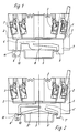
- the protective conductor terminals shown in Figures 1 and 2 have the usual insulating housing 1, in which busbars 2 are inserted, which are equipped with conductor connections 3 of any known type.
- the busbars 2 are electrically and mechanically firmly connected to a fastening and contact foot 4, 4 ', which in turn serves for the electrical connection of the busbar and the mechanical connection of the terminal as a whole with a mounting rail 5, which in such protective conductor terminals serves as a protective conductor busbar.
- the fastening and contact foot 4 has two hook elements 6 and 7, which practically have spring action due to their shape.
- a particularly long strut 8 in one piece. It begins on one side in the vicinity of the hook element 6 and runs from there over a considerable part of the mounting rail width to the other hook element 7.
- the hook element 7 has a bearing slope 9 which is dimensioned so long that space of different lengths and different thicknesses of mounting rails for different mounting rails can be accommodated.
- the strut 8 acts on the top of the support rail leg lying on the bearing slope 9.
- the opposite hook element 6, which serves as a fixed bearing, has a control slope 10, which is followed by a groove-like receptacle 11 for the free end of the other mounting rail leg.
- the fastening and contact foot is first connected in an inclined position to the hook element 7 and the spring strut 8 to the corresponding mounting rail leg.
- the other mounting rail leg runs along the control bevel 10 towards the receptacle 11, with other mounting rail legs correspondingly pushing up on the bevel 9 of the hook element 7.
- the end position is secured by the spring strut 8.
- carrier rail legs of different configurations can thus be used.
- the fastening and contact foot 4 maintains a simple profile and has a particularly long spring strut 8, which is therefore particularly suitable for the intended function.
- FIG. 2 a protective conductor terminal of basically the same construction is shown in FIG. 2, which now has a fastening and contact foot 4 ′, which, starting from approximately the central region, has two shorter spring struts 8 ′ and 8 ′′, each of which stretches from there to one of the mounting rail legs to get lost and with the top of which work together.
- the hook elements 6 and 7 are held in their geometry so that they also have spring action again.
- the hook elements 6 and 7 thus again act like suspension struts.
- the overall required and desired spring strut effect can thus be distributed over a total of four spring-acting elements, with which one can achieve a particularly secure suspension on the mounting rail with good handling with respect to the locking on the mounting rail with a corresponding design.
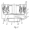
- a fastening and contact foot 4 ′′ is provided, in which the one hook element 7 ′ has an extended spring travel.
- the hook element 7 ' is extended laterally beyond the mounting rail and then bent back again in a C-shape to the corresponding mounting rail leg.
- the hook element 7 ' At its end interacting with this mounting rail leg, the hook element 7 'has a bearing slope 9'.
- due to the longer spring travel of the hook element 7 ' it is particularly possible to ensure tolerance compensation for the different dimensions of the mounting rails.
- only one spring strut 8 ''' is again provided, which, however, can be relatively short in itself with regard to the suspension properties of the arrangement and is shown in FIG Exemplary embodiment extends approximately from the center of this fastening and contact foot 4 ′′ to the C-shaped hook element 7 ′.
Landscapes
- Connections Arranged To Contact A Plurality Of Conductors (AREA)
- Elimination Of Static Electricity (AREA)
- Mounting Components In General For Electric Apparatus (AREA)
- Insulated Conductors (AREA)
Applications Claiming Priority (2)
| Application Number | Priority Date | Filing Date | Title |
|---|---|---|---|
| DE4203184 | 1992-02-05 | ||
| DE4203184A DE4203184C3 (de) | 1992-02-05 | 1992-02-05 | Schutzleiterklemme |
Publications (3)
| Publication Number | Publication Date |
|---|---|
| EP0554519A2 true EP0554519A2 (fr) | 1993-08-11 |
| EP0554519A3 EP0554519A3 (fr) | 1994-04-27 |
| EP0554519B1 EP0554519B1 (fr) | 1996-09-18 |
Family
ID=6450956
Family Applications (1)
| Application Number | Title | Priority Date | Filing Date |
|---|---|---|---|
| EP92118478A Expired - Lifetime EP0554519B1 (fr) | 1992-02-05 | 1992-10-29 | Borne de raccordement avec mise à la terre |
Country Status (6)
| Country | Link |
|---|---|
| US (1) | US5334054A (fr) |
| EP (1) | EP0554519B1 (fr) |
| JP (1) | JP2509432B2 (fr) |
| AT (1) | ATE143180T1 (fr) |
| DE (2) | DE4203184C3 (fr) |
| ES (1) | ES2092614T3 (fr) |
Cited By (4)
| Publication number | Priority date | Publication date | Assignee | Title |
|---|---|---|---|---|
| US6329335B1 (en) | 1997-03-07 | 2001-12-11 | Henkel Kommanditgesellschaft Auf Aktien | Detergent tablets |
| EP1357642A3 (fr) * | 2002-04-26 | 2004-11-24 | WIELAND ELECTRIC GmbH | Dispositif de raccordement |
| CN109983627A (zh) * | 2016-11-21 | 2019-07-05 | 菲尼克斯电气公司 | 用于连接端子的汇流条 |
| EP3540861A1 (fr) * | 2018-03-14 | 2019-09-18 | OMRON Corporation | Prise |
Families Citing this family (32)
| Publication number | Priority date | Publication date | Assignee | Title |
|---|---|---|---|---|
| US5425655A (en) * | 1993-10-20 | 1995-06-20 | The West Bend Company | Appliance enclosure and related terminal block |
| DE4409206C1 (de) * | 1994-03-17 | 1995-05-11 | Phoenix Contact Gmbh & Co | Fuß für eine elektrische Schutzleiterklemme sowie Schutzleiterklemme |
| FR2732518B1 (fr) * | 1995-03-29 | 1997-04-30 | Entrelec Sa | Agencement de connexion pour fils conducteurs electriques et module, notamment de type bloc de jonction, equipe d'un tel agencement |
| EP0751585B1 (fr) * | 1995-06-28 | 2000-01-19 | Siemens Aktiengesellschaft | Butée d'arrêt pour barrettes de raccordement |
| US5816867A (en) * | 1996-08-22 | 1998-10-06 | Allen Bradley Company, Llc | Curved wire spring clamp with optimized bending stress distribution |
| DE19646696C1 (de) * | 1996-11-12 | 1998-04-30 | Puls Elektronische Stromversor | Halteteil, Gehäuse mit einem Halteteil und Schiebeteil |
| DE19708911C1 (de) * | 1997-03-05 | 1998-07-30 | Weidmueller Interface | Schutzleiteranschluß |
| DE19729327C1 (de) * | 1997-07-09 | 1998-10-29 | Wieland Electric Gmbh | Schutzleiterklemme |
| DE19818704C1 (de) * | 1998-04-19 | 1999-11-04 | Wago Verwaltungs Gmbh | Montagefuß mit Schutzleiterfunktion für elektr. Klemmen |
| FR2792464B1 (fr) * | 1999-04-15 | 2001-09-14 | Realisations Jlp | Borne de connexion electrique et barrette formee d'un empilement de telles bornes |
| KR100322350B1 (ko) * | 2000-01-19 | 2002-02-07 | 윤흥식 | 단자대의 링크스트립 |
| DE10041279C2 (de) * | 2000-08-22 | 2002-11-21 | Phoenix Contact Gmbh & Co | Elektrische Reihenklemme |
| US6543957B1 (en) | 2000-09-14 | 2003-04-08 | Puls Elecktronische Stromversorgungen Gmbh | Holder and housing comprising at least one holder |
| GB2381132A (en) * | 2001-10-16 | 2003-04-23 | Channell Ltd | Telecommunication connector for connection to an earth rail |
| DE10315668B4 (de) * | 2002-08-28 | 2007-06-06 | Conrad Stanztechnik Gmbh | Anschlußklemme |
| DE10324144B4 (de) * | 2003-05-26 | 2005-09-01 | Phoenix Contact Gmbh & Co. Kg | Elektrische Reihenklemme und metallisches Schutzleiteranschlußelement zur Verwendung in einer elektrischen Reihenklemme |
| EP1615307A1 (fr) * | 2004-07-06 | 2006-01-11 | Puls Elektronische Stromversorgungs GmbH | Support pour la fixation d'un couvercle à un rail, et une couvercle ou appareil électrique avec un support |
| DE102005040657A1 (de) * | 2005-08-26 | 2007-03-15 | Phoenix Contact Gmbh & Co. Kg | Elektrische Anschlussklemme |
| JP4760429B2 (ja) * | 2006-02-15 | 2011-08-31 | 富士電機機器制御株式会社 | 電気機器のレール取付け構造 |
| JP2007299936A (ja) * | 2006-04-28 | 2007-11-15 | Sunx Ltd | 電子機器の取付構造 |
| DE102006049019B4 (de) * | 2006-10-13 | 2009-11-26 | Phoenix Contact Gmbh & Co. Kg | Montageplatte mit Befestigungsmitteln für ein elektrisches Gerät |
| DE102007041979B3 (de) * | 2007-09-05 | 2009-03-19 | Conrad Stanztechnik Gmbh | Stromschienenanordnung für eine elektrische Anschlussvorrichtung, insbesondere eine Neutral-Leiter-Schutzklemme, eine Schutzleiterklemme und eine Reihenklemme |
| DE202008015309U1 (de) * | 2008-02-02 | 2009-08-13 | Weidmüller Interface GmbH & Co. KG | Montagesystem für elektrische und/oder mechanische Komponenten |
| EP2086077A3 (fr) * | 2008-02-02 | 2013-07-24 | Weidmüller Interface GmbH & Co. KG | Système de montage pour composants électriques et/ou mécaniques |
| JP5043725B2 (ja) * | 2008-03-14 | 2012-10-10 | 東洋技研株式会社 | 据付レール用固定金具 |
| DE102009010918A1 (de) | 2009-02-27 | 2010-09-09 | Agfeo Gmbh & Co. Kg | Vorrichtung zum Einrichten eines Datenübertragungsnetzes |
| EP2483977B1 (fr) | 2009-09-29 | 2014-11-12 | Panduit Corp. | Adaptateur pour un rail de support avec mise a la terre |
| FR3026238B1 (fr) * | 2014-09-23 | 2016-10-21 | Abb France | Partie de barre conductrice pour un appareil electrique |
| DE102014115048A1 (de) * | 2014-10-16 | 2016-04-21 | Phoenix Contact Gmbh & Co. Kg | Klemmeneinrichtung mit einer Stromschiene |
| DE102016113480A1 (de) * | 2016-07-21 | 2018-01-25 | Wago Verwaltungsgesellschaft Mbh | Metallischer Kontaktfuß eines Schutzleiteranschlusselementes und Schutzleiteranschlusselement |
| EP3376617B1 (fr) * | 2017-03-14 | 2019-01-09 | Sick AG | Dispositif de fixation |
| GB2598948B (en) * | 2020-09-21 | 2022-10-12 | Hager Engineering Ltd | Connection device for an electrical apparatus |
Citations (3)
| Publication number | Priority date | Publication date | Assignee | Title |
|---|---|---|---|---|
| CH532253A (de) * | 1972-04-05 | 1972-12-31 | Oskar Woertz Inh H & O Woertz | Elektrische Klemme zum Anbringen an einer Profilschiene mit Flanschen |
| DE7712331U1 (de) * | 1977-04-20 | 1977-11-17 | Wago-Kontakttechnik Gmbh, 4950 Minden | Reihenklemme zum Anschließen und Verbinden von elektrischen Leitungen |
| CH629038A5 (en) * | 1978-06-13 | 1982-03-31 | Sprecher & Schuh Ag | Protective-earth conductor terminal strip for DIN rails |
Family Cites Families (7)
| Publication number | Priority date | Publication date | Assignee | Title |
|---|---|---|---|---|
| FR83883E (fr) * | 1963-06-24 | 1964-10-31 | Telemecanique Electrique | Dispositif élastique de fixation de bornes électriques destinées à être montées en file sur un profilé en forme de c |
| DE7829303U1 (de) * | 1978-09-30 | 1981-11-05 | Wago-Kontakttechnik Gmbh, 4950 Minden | Vorrichtung zur Schnappbefestigung von elektrischen Geräten, Reihenklemmen o.dgl. auf Tragschienen |
| DE3770949D1 (de) * | 1986-01-23 | 1991-08-01 | Siemens Ag | Schutzleiteranschlussklemme. |
| DE3732267C1 (en) * | 1987-09-25 | 1988-09-22 | Phoenix Elekt | Electrical terminal block |
| DE3805158A1 (de) * | 1988-02-15 | 1989-08-24 | Wago Verwaltungs Gmbh | Reihenklemme zur zweileiter-stromversorgung von elektrischen oder elektronischen bauelementen, insbesondere initiatoren |
| DE3903752A1 (de) * | 1989-02-06 | 1990-08-09 | Wago Verwaltungs Gmbh | Schutzleiter-reihenklemme |
| DE58908455D1 (de) * | 1989-05-12 | 1994-11-03 | Weidmueller Interface | Reihenklemmenanordnung. |
-
1992
- 1992-02-05 DE DE4203184A patent/DE4203184C3/de not_active Expired - Fee Related
- 1992-10-29 ES ES92118478T patent/ES2092614T3/es not_active Expired - Lifetime
- 1992-10-29 AT AT92118478T patent/ATE143180T1/de active
- 1992-10-29 EP EP92118478A patent/EP0554519B1/fr not_active Expired - Lifetime
- 1992-10-29 DE DE59207184T patent/DE59207184D1/de not_active Expired - Lifetime
-
1993
- 1993-01-25 US US08/008,544 patent/US5334054A/en not_active Expired - Lifetime
- 1993-02-02 JP JP5015291A patent/JP2509432B2/ja not_active Expired - Lifetime
Patent Citations (3)
| Publication number | Priority date | Publication date | Assignee | Title |
|---|---|---|---|---|
| CH532253A (de) * | 1972-04-05 | 1972-12-31 | Oskar Woertz Inh H & O Woertz | Elektrische Klemme zum Anbringen an einer Profilschiene mit Flanschen |
| DE7712331U1 (de) * | 1977-04-20 | 1977-11-17 | Wago-Kontakttechnik Gmbh, 4950 Minden | Reihenklemme zum Anschließen und Verbinden von elektrischen Leitungen |
| CH629038A5 (en) * | 1978-06-13 | 1982-03-31 | Sprecher & Schuh Ag | Protective-earth conductor terminal strip for DIN rails |
Cited By (5)
| Publication number | Priority date | Publication date | Assignee | Title |
|---|---|---|---|---|
| US6329335B1 (en) | 1997-03-07 | 2001-12-11 | Henkel Kommanditgesellschaft Auf Aktien | Detergent tablets |
| EP1357642A3 (fr) * | 2002-04-26 | 2004-11-24 | WIELAND ELECTRIC GmbH | Dispositif de raccordement |
| CN109983627A (zh) * | 2016-11-21 | 2019-07-05 | 菲尼克斯电气公司 | 用于连接端子的汇流条 |
| EP3540861A1 (fr) * | 2018-03-14 | 2019-09-18 | OMRON Corporation | Prise |
| US10511109B2 (en) | 2018-03-14 | 2019-12-17 | Omron Corporation | Socket with locking parts to secure to a rail |
Also Published As
| Publication number | Publication date |
|---|---|
| EP0554519A3 (fr) | 1994-04-27 |
| DE59207184D1 (de) | 1996-10-24 |
| DE4203184C2 (de) | 1993-12-02 |
| JP2509432B2 (ja) | 1996-06-19 |
| EP0554519B1 (fr) | 1996-09-18 |
| US5334054A (en) | 1994-08-02 |
| DE4203184A1 (de) | 1993-08-12 |
| ES2092614T3 (es) | 1996-12-01 |
| DE4203184C3 (de) | 1996-11-21 |
| ATE143180T1 (de) | 1996-10-15 |
| JPH06318477A (ja) | 1994-11-15 |
Similar Documents
| Publication | Publication Date | Title |
|---|---|---|
| EP0554519B1 (fr) | Borne de raccordement avec mise à la terre | |
| EP3745538A1 (fr) | Borne de raccordement de conducteur | |
| EP1100150B1 (fr) | Borne à ressort pour des grandes sections transversales de conducteurs | |
| EP0334975B1 (fr) | Connexion de conducteur | |
| DE4409206C1 (de) | Fuß für eine elektrische Schutzleiterklemme sowie Schutzleiterklemme | |
| DE69905932T2 (de) | Stromschiene für eine elektrische energieverteilung | |
| EP3282518A1 (fr) | Une borne à ressort destinée au contact d'un conducteur électrique | |
| EP0086316B1 (fr) | Dispositif à contact enfichable pour la réalisation d'une connexion électrique entre deux barres omnibus | |
| DE69303065T2 (de) | Verbinderklemme mit Sattel veränderlicher Dicke und mit eingefasster Mutter | |
| EP3261185B1 (fr) | Insert de contact d'une borne de raccordement à ressort de connexion et borne de raccordement à ressort de connexion | |
| DE3732267C1 (en) | Electrical terminal block | |
| AT506801B1 (de) | Nh-sicherungsschaltgerät | |
| EP1182735B1 (fr) | Réglette d'interconnexion électrique | |
| DE19818704C1 (de) | Montagefuß mit Schutzleiterfunktion für elektr. Klemmen | |
| DE7717019U1 (de) | Reihentrennklemme | |
| DE3418667A1 (de) | Klemmvorrichtung mit einer oder mehreren anschlussklemmen fuer elektrische kontaktelemente, fuer transformatoren od. dgl. | |
| DE2427476C3 (de) | Elektrische Schaltausriistung | |
| DE2701720C2 (de) | Kippschalter | |
| DE1246079B (de) | Anschlussklemme, insbesondere in Geraetesockeln | |
| EP1026801B1 (fr) | Bloc de contacts mobile pour interrupteur de puissance extractible | |
| DE2051781A1 (de) | Schraubklemmen für elektrische Leitungen | |
| DE370088C (de) | Drehschalter mit saeulenfoermigem Sockel | |
| DE3128157C2 (de) | Elektrische Reihenklemme | |
| DE102020129342A1 (de) | Direktsteck-Druckfederanschluss | |
| EP0404755B1 (fr) | Systèmes de barres omnibus pour boîtes de distribution |
Legal Events
| Date | Code | Title | Description |
|---|---|---|---|
| PUAI | Public reference made under article 153(3) epc to a published international application that has entered the european phase |
Free format text: ORIGINAL CODE: 0009012 |
|
| AK | Designated contracting states |
Kind code of ref document: A2 Designated state(s): AT CH DE ES FR GB IT LI SE |
|
| PUAL | Search report despatched |
Free format text: ORIGINAL CODE: 0009013 |
|
| AK | Designated contracting states |
Kind code of ref document: A3 Designated state(s): AT CH DE ES FR GB IT LI SE |
|
| 17P | Request for examination filed |
Effective date: 19940322 |
|
| GRAG | Despatch of communication of intention to grant |
Free format text: ORIGINAL CODE: EPIDOS AGRA |
|
| GRAH | Despatch of communication of intention to grant a patent |
Free format text: ORIGINAL CODE: EPIDOS IGRA |
|
| 17Q | First examination report despatched |
Effective date: 19960229 |
|
| ITF | It: translation for a ep patent filed | ||
| GRAH | Despatch of communication of intention to grant a patent |
Free format text: ORIGINAL CODE: EPIDOS IGRA |
|
| GRAA | (expected) grant |
Free format text: ORIGINAL CODE: 0009210 |
|
| AK | Designated contracting states |
Kind code of ref document: B1 Designated state(s): AT CH DE ES FR GB IT LI SE |
|
| REF | Corresponds to: |
Ref document number: 143180 Country of ref document: AT Date of ref document: 19961015 Kind code of ref document: T |
|
| REG | Reference to a national code |
Ref country code: CH Ref legal event code: NV Representative=s name: ISLER & PEDRAZZINI AG |
|
| REF | Corresponds to: |
Ref document number: 59207184 Country of ref document: DE Date of ref document: 19961024 |
|
| GBT | Gb: translation of ep patent filed (gb section 77(6)(a)/1977) |
Effective date: 19961101 |
|
| REG | Reference to a national code |
Ref country code: ES Ref legal event code: FG2A Ref document number: 2092614 Country of ref document: ES Kind code of ref document: T3 |
|
| ET | Fr: translation filed | ||
| PLBE | No opposition filed within time limit |
Free format text: ORIGINAL CODE: 0009261 |
|
| STAA | Information on the status of an ep patent application or granted ep patent |
Free format text: STATUS: NO OPPOSITION FILED WITHIN TIME LIMIT |
|
| 26N | No opposition filed | ||
| REG | Reference to a national code |
Ref country code: GB Ref legal event code: IF02 |
|
| REG | Reference to a national code |
Ref country code: CH Ref legal event code: PCAR Free format text: ISLER & PEDRAZZINI AG;POSTFACH 1772;8027 ZUERICH (CH) |
|
| PGFP | Annual fee paid to national office [announced via postgrant information from national office to epo] |
Ref country code: AT Payment date: 20101014 Year of fee payment: 19 |
|
| PGFP | Annual fee paid to national office [announced via postgrant information from national office to epo] |
Ref country code: DE Payment date: 20101022 Year of fee payment: 19 |
|
| PGFP | Annual fee paid to national office [announced via postgrant information from national office to epo] |
Ref country code: GB Payment date: 20101021 Year of fee payment: 19 Ref country code: IT Payment date: 20101026 Year of fee payment: 19 |
|
| PGFP | Annual fee paid to national office [announced via postgrant information from national office to epo] |
Ref country code: SE Payment date: 20111021 Year of fee payment: 20 Ref country code: FR Payment date: 20111103 Year of fee payment: 20 Ref country code: CH Payment date: 20111024 Year of fee payment: 20 Ref country code: ES Payment date: 20111026 Year of fee payment: 20 |
|
| REG | Reference to a national code |
Ref country code: DE Ref legal event code: R071 Ref document number: 59207184 Country of ref document: DE |
|
| REG | Reference to a national code |
Ref country code: DE Ref legal event code: R071 Ref document number: 59207184 Country of ref document: DE |
|
| REG | Reference to a national code |
Ref country code: CH Ref legal event code: PL |
|
| REG | Reference to a national code |
Ref country code: GB Ref legal event code: PE20 Expiry date: 20121028 |
|
| REG | Reference to a national code |
Ref country code: SE Ref legal event code: EUG |
|
| REG | Reference to a national code |
Ref country code: AT Ref legal event code: MK07 Ref document number: 143180 Country of ref document: AT Kind code of ref document: T Effective date: 20121029 |
|
| PG25 | Lapsed in a contracting state [announced via postgrant information from national office to epo] |
Ref country code: GB Free format text: LAPSE BECAUSE OF EXPIRATION OF PROTECTION Effective date: 20121028 |
|
| PG25 | Lapsed in a contracting state [announced via postgrant information from national office to epo] |
Ref country code: ES Free format text: LAPSE BECAUSE OF EXPIRATION OF PROTECTION Effective date: 20121030 |