EP0553530B1 - Information recording/reproducing apparatus using an optical recording medium - Google Patents
Information recording/reproducing apparatus using an optical recording medium Download PDFInfo
- Publication number
- EP0553530B1 EP0553530B1 EP92306989A EP92306989A EP0553530B1 EP 0553530 B1 EP0553530 B1 EP 0553530B1 EP 92306989 A EP92306989 A EP 92306989A EP 92306989 A EP92306989 A EP 92306989A EP 0553530 B1 EP0553530 B1 EP 0553530B1
- Authority
- EP
- European Patent Office
- Prior art keywords
- data
- information
- bit
- recording
- recording medium
- Prior art date
- Legal status (The legal status is an assumption and is not a legal conclusion. Google has not performed a legal analysis and makes no representation as to the accuracy of the status listed.)
- Expired - Lifetime
Links
- 230000003287 optical effect Effects 0.000 title claims description 43
- 238000006243 chemical reaction Methods 0.000 claims description 37
- 238000001514 detection method Methods 0.000 claims description 4
- 238000000034 method Methods 0.000 description 5
- 238000010586 diagram Methods 0.000 description 4
- 238000000605 extraction Methods 0.000 description 3
- 230000008569 process Effects 0.000 description 3
- 230000004044 response Effects 0.000 description 3
- 238000000926 separation method Methods 0.000 description 3
- 230000007704 transition Effects 0.000 description 3
- 230000006870 function Effects 0.000 description 2
- 230000009467 reduction Effects 0.000 description 1
Images
Classifications
-
- H—ELECTRICITY
- H03—ELECTRONIC CIRCUITRY
- H03M—CODING; DECODING; CODE CONVERSION IN GENERAL
- H03M13/00—Coding, decoding or code conversion, for error detection or error correction; Coding theory basic assumptions; Coding bounds; Error probability evaluation methods; Channel models; Simulation or testing of codes
- H03M13/03—Error detection or forward error correction by redundancy in data representation, i.e. code words containing more digits than the source words
-
- G—PHYSICS
- G11—INFORMATION STORAGE
- G11B—INFORMATION STORAGE BASED ON RELATIVE MOVEMENT BETWEEN RECORD CARRIER AND TRANSDUCER
- G11B20/00—Signal processing not specific to the method of recording or reproducing; Circuits therefor
- G11B20/10—Digital recording or reproducing
- G11B20/14—Digital recording or reproducing using self-clocking codes
- G11B20/1403—Digital recording or reproducing using self-clocking codes characterised by the use of two levels
- G11B20/1423—Code representation depending on subsequent bits, e.g. delay modulation, double density code, Miller code
- G11B20/1426—Code representation depending on subsequent bits, e.g. delay modulation, double density code, Miller code conversion to or from block codes or representations thereof
-
- G—PHYSICS
- G11—INFORMATION STORAGE
- G11B—INFORMATION STORAGE BASED ON RELATIVE MOVEMENT BETWEEN RECORD CARRIER AND TRANSDUCER
- G11B20/00—Signal processing not specific to the method of recording or reproducing; Circuits therefor
- G11B20/10—Digital recording or reproducing
- G11B20/18—Error detection or correction; Testing, e.g. of drop-outs
-
- H—ELECTRICITY
- H03—ELECTRONIC CIRCUITRY
- H03M—CODING; DECODING; CODE CONVERSION IN GENERAL
- H03M5/00—Conversion of the form of the representation of individual digits
- H03M5/02—Conversion to or from representation by pulses
- H03M5/04—Conversion to or from representation by pulses the pulses having two levels
- H03M5/14—Code representation, e.g. transition, for a given bit cell depending on the information in one or more adjacent bit cells, e.g. delay modulation code, double density code
- H03M5/145—Conversion to or from block codes or representations thereof
Definitions
- the present invention relates to an information recording/reproducing apparatus using an optical recording medium such as an optical disk.
- Recording and reproducing systems for an optical disk can be considered as a kind of low-pass filters in view of the OTF (Optical Transfer Function) of an objective lens and the response characteristic or the like of a recording material. If information is recorded with a high linear recording density increased to near the upper limit of the frequency response of the recording and reproducing systems, a read error occurs due to a so-called code interference by which reproduced waveforms are likely to interfere each other at the time adjacent marks are read.
- OTF Optical Transfer Function
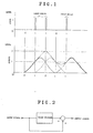
- the recording and reproducing systems for an optical disk can be said to be approximated to a PR (1,1) transfer path (Partial Response Transfer Path) as shown in Fig. 2.
- the PR (1,1) transfer path shows a characteristic such that, when a train of input signals has a digitized value, the output has a ternary value.
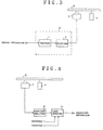
- Fig. 3 illustrates the structure of a conventional information recording apparatus for an optical disk.
- record information digitized to have values "0" and "1" is supplied to a precoder 1.
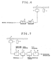
- the precoder 1 modulates data before inputting the data to the PR (1,1) transfer path, and is equivalent to a transfer path which processes input data with the opposite characteristic to that of the PR (1,1) transfer path, as shown in Fig. 5.
- the output of the precoder 1 is supplied via a digitizer 2 to an optical head 3.
- the digitizer 2 digitizes other values than "0" and "1” which are produced by the precoder 1, and may be designed to divide an input value by "2" and output the remainder.
- the optical head 3 performs photoelectric conversion on the output of the digitizer 2 and records the resultant signal on an optical disk which is rotated by a spindle motor 4.
- NRZi modulation Non Return to Zero Inverting
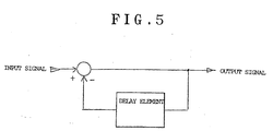
- Fig. 4 illustrates the structure of a conventional information reproducing apparatus for an optical disk.
- an optical pickup 7 accesses the optical disk 5 for information reading, yielding a reproduced signal.
- the reproduced signal is amplified by an equalizer amplifier 8 before it is supplied to a level detector 9.
- the level detector 9 digitizes the ternary reproduced signal to restore it to the original record information and outputs the reproduced information.
- the process the optical pickup 7 performs to read information from the optical disk 5 is equivalent to the PR (1,1) transfer path due to the code interference.
- the reproduced signal therefore is a ternary signal having values of "0", "1" and "2".
- the level detector 9 compares the level of the signal from the equalizer amplifier 8 with first and second threshold levels.
- the level detector 9 is designed to output "0" when the level of the signal from the equalizer amplifier 8 is lower than the first threshold level or equal to or higher than the second threshold level, and output "1" when the level of that signal is equal to or higher than the first threshold level and lower than the second threshold level.
- the conventional recording and reproducing systems for an optical disk designed to have a high linear recording density should separate and extract a ternary signal using two threshold levels.
- This separation/extraction of a signal accurately converted to have three values requires a higher S/N ratio in the reproduced signal than the separation and extraction of a digital signal by a single threshold level, and is therefore practically difficult to accomplish.
- DE-A-2 947 874 discloses an information recording apparatus using an optical recording medium, in which n-bit words are converted to m-bit words according to a predetermined data conversion table, and the converted words are NRZi modulated.
- a first aspect of the present invention provides an information recording apparatus using an optical recording medium, comprising
- a second aspect of the present invention provides an information reproducing apparatus for an optical recording medium on which information is recorded by the information recording apparatus of claim 1, the apparatus comprising
- the information recording apparatus performs data conversion in such a way that "1" does not appear three or more times in a row in a train of information data at the time of recording information data on a recording medium, and the information reproducing apparatus restores the data converted by this data conversion to the original information data.
- Figs. 6 and 7 illustrate the structures of the information recording and reproducing apparatuses respectively using an optical recording medium according to the present invention.
- the information recording and reproducing apparatuses perform information recording and information reproduction in the units of eight bits.
- the information recording apparatus in Fig. 6 embodying the present invention causes an 8-to-13 converter 10 to perform data conversion before NRZi modulation in such a way that "1" will not appear three or more times in a row in a train of information data after the NRZi modulation.
- the 8-to-13 converter 10 performs data conversion to expand 8-bit input record information to 13-bit data according to one of the following rules.
- a pattern after conversion consists of at least one "0" and an even number of consecutive "1".
- a pattern after conversion includes a section consisting of "01010” and a section consisting of at least one "0” or an even number of consecutive "1".
- the 8-to-13 converter 10 Since the 8-to-13 converter 10 has no output rule to an input, a user needs to arbitrarily prepare output patterns following the above rules, and prepare a data conversion table which associates the output patterns with input data. Tables 1 through 9 show examples of the data conversion table which associates the output patterns with input data. Tables 1 through 7 are prepared according to the rule (1), and tables 8 and 9 according to the rule (2).
- the 8-to-13 converter 10 may be constituted of a ROM (Read Only Memory) where the output patterns are recorded as data at addresses specified by the input data.
- NRZi modulator 6 Data after 8-to-13 conversion is supplied to an NRZi modulator 6 to become NRZi data. This NRZi data is then supplied to an optical head 3 to be recorded on an optical disk 5.
- An optical pickup 7 picks up information from the optical disk 5 and supplies the acquired reproduced signal to an equalizer amplifier 8.
- the reproduced signal amplified by the equalizer amplifier 8 is sent to a level detector 11.
- the level detector 11 compares the level of the signal from the equalizer amplifier 8 with a threshold level as a reference for level discrimination to acquire digital data from the reproduced signal.
- the level detector 11 sends digital data of "0" to an error correcting circuit 12 when the level of the signal from the equalizer amplifier 8 is lower than the threshold level, and sends digital data of "1" to the error correcting circuit 12 when that signal level is equal to or higher than the threshold level.
- the error correcting circuit 12 corrects it to "01010" and sends the corrected data to a 13-to-8 converter 13.
- the error correcting circuit 12 performs no error correction and sends the received data directly to the 13-to-8 converter 13.
- the 13-to-8 converter 13 refers to the data conversion table in the reverse manner to the one done by the 8-to-13 converter 10 to convert 13-bit data to 8-bit data, and outputs the resultant data as reproduced information.
- Tables 1 through 9 are to be referred to as data conversion tables for 8-to-13 conversion.
- the numbers of bits, "8" and “13", in the 8-to-13 conversion and 13-to-8 conversion are determined for the apparatuses according to this embodiment, which perform information recording and reduction in the units of 8 bits, but those numbers may be arbitrarily determined by a user as long as they satisfy the rules (1) and (2).
- the information recording/reproducing apparatus using an optical recording medium inhibits "1" from consecutively appearing in data or performs data conversion to restrict the number of consecutive appearing "1" to two at a maximum before recording record information on a disk.
- two values "0” and “1” have only to be detected, so that the reproduced signal does not require a higher S/N ratio than that acquired by the convention apparatus which detects three values of level, "0", "1” and "2".
- the present invention can therefore provide an information recording/reproducing apparatus for an optical recording medium designed to have a high linear recording density.
Landscapes
- Engineering & Computer Science (AREA)
- Theoretical Computer Science (AREA)
- Signal Processing (AREA)
- Physics & Mathematics (AREA)
- Probability & Statistics with Applications (AREA)
- Signal Processing For Digital Recording And Reproducing (AREA)
- Optical Recording Or Reproduction (AREA)
Applications Claiming Priority (2)
| Application Number | Priority Date | Filing Date | Title |
|---|---|---|---|
| JP00860592A JP3305344B2 (ja) | 1992-01-21 | 1992-01-21 | 光学式記録媒体を用いた情報記録再生装置 |
| JP8605/92 | 1992-01-21 |
Publications (3)
| Publication Number | Publication Date |
|---|---|
| EP0553530A2 EP0553530A2 (en) | 1993-08-04 |
| EP0553530A3 EP0553530A3 (enExample) | 1995-01-25 |
| EP0553530B1 true EP0553530B1 (en) | 1997-09-17 |
Family
ID=11697595
Family Applications (1)
| Application Number | Title | Priority Date | Filing Date |
|---|---|---|---|
| EP92306989A Expired - Lifetime EP0553530B1 (en) | 1992-01-21 | 1992-07-31 | Information recording/reproducing apparatus using an optical recording medium |
Country Status (4)
| Country | Link |
|---|---|
| US (1) | US5392270A (enExample) |
| EP (1) | EP0553530B1 (enExample) |
| JP (1) | JP3305344B2 (enExample) |
| DE (1) | DE69222286T2 (enExample) |
Families Citing this family (7)
| Publication number | Priority date | Publication date | Assignee | Title |
|---|---|---|---|---|
| JP3224181B2 (ja) * | 1993-11-09 | 2001-10-29 | 富士通株式会社 | 光ディスクからのデータ再生システム |
| JP3432003B2 (ja) * | 1994-07-06 | 2003-07-28 | キヤノン株式会社 | 情報再生装置及び情報記録再生装置 |
| JP3541439B2 (ja) * | 1994-07-08 | 2004-07-14 | ソニー株式会社 | 信号変調方法及び装置、並びに信号復調装置及び方法 |
| EP0821360B1 (en) * | 1996-02-08 | 2003-08-20 | Sony Corporation | Data decoder |
| JP3539091B2 (ja) * | 1996-10-11 | 2004-06-14 | ソニー株式会社 | データ復号方法及びデータ復号装置 |
| KR100370223B1 (ko) | 2001-02-05 | 2003-02-05 | 삼성전자 주식회사 | 데이터 기록/재생 장치 및 그 방법과 데이터 부호화 방법 |
| CN1308929C (zh) * | 2005-02-01 | 2007-04-04 | 威盛电子股份有限公司 | 一种测试光盘的制作方法 |
Family Cites Families (7)
| Publication number | Priority date | Publication date | Assignee | Title |
|---|---|---|---|---|
| DE2947874C2 (de) * | 1979-11-28 | 1985-03-21 | Institut für Rundfunktechnik GmbH, 8000 München | Einrichtung zum Aufzeichnen von Videosignalen in digitaler Form auf einen magnetischen Informationsträger sowie Einrichtung zum Abnehmen von in digitaler Form aufgezeichneten Videosignalen auf einem magnetischen Informationsträger |
| FR2507035B1 (fr) * | 1981-06-02 | 1988-09-16 | Thomson Csf | Procede de codage de donnees binaires et dispositif de transmission de signal video numerise mettant en oeuvre un tel procede |
| US4484176A (en) * | 1982-11-24 | 1984-11-20 | Storage Technology Corporation | Run length limited data encoder |
| US4833471A (en) * | 1984-03-26 | 1989-05-23 | Canon Kabushiki Kaisha | Data processing apparatus |
| US4584616A (en) * | 1984-07-12 | 1986-04-22 | Tallgrass Technologies Corporation | Format for storing data on magnetic media |
| JP2810035B2 (ja) * | 1986-08-22 | 1998-10-15 | 株式会社日立製作所 | 光学的記録再生方法 |
| JPH01208769A (ja) * | 1988-02-16 | 1989-08-22 | Csk Corp | バーストエラー訂正装置 |
-
1992
- 1992-01-21 JP JP00860592A patent/JP3305344B2/ja not_active Expired - Fee Related
- 1992-07-31 DE DE69222286T patent/DE69222286T2/de not_active Expired - Fee Related
- 1992-07-31 EP EP92306989A patent/EP0553530B1/en not_active Expired - Lifetime
-
1994
- 1994-06-06 US US08/254,433 patent/US5392270A/en not_active Expired - Lifetime
Also Published As
| Publication number | Publication date |
|---|---|
| JP3305344B2 (ja) | 2002-07-22 |
| EP0553530A3 (enExample) | 1995-01-25 |
| DE69222286D1 (de) | 1997-10-23 |
| JPH05198100A (ja) | 1993-08-06 |
| EP0553530A2 (en) | 1993-08-04 |
| US5392270A (en) | 1995-02-21 |
| DE69222286T2 (de) | 1998-02-12 |
Similar Documents
| Publication | Publication Date | Title |
|---|---|---|
| US5909417A (en) | Recording medium formatted for error correction and high density recording and an apparatus for recording information thereon and/or reproducing information therefrom | |
| CA2024344A1 (en) | Digital data transmission system having error detecting and correcting function | |
| EP0347934A3 (en) | Data recording and/or reproducing method and data recording medium | |
| EP0553530B1 (en) | Information recording/reproducing apparatus using an optical recording medium | |
| US4516163A (en) | Digital information signal recording system | |
| US4546393A (en) | Digital data transmission system with modified NRZI | |
| GB2226688A (en) | Magnetic disk drive apparatus | |
| US7457210B2 (en) | High-density disk recording medium and apparatus and method of reproducing data recorded therein | |
| US7342854B2 (en) | Apparatus for generating tracking error signals | |
| JP3439680B2 (ja) | ディジタル変調回路 | |
| JP2843350B2 (ja) | データ記録再生装置 | |
| JP3135567B2 (ja) | Nrz2進入力信号評価回路および方法 | |
| JP2621438B2 (ja) | 記録信号再生装置 | |
| JPS59110012A (ja) | Pcm信号記録方式 | |
| KR100207695B1 (ko) | 디지탈신호 재생장치 및 그 방법 | |
| JPH02194733A (ja) | 4/11符号生成方法及び装置 | |
| JPS6229322A (ja) | デ−タ伝送装置 | |
| JPH02235263A (ja) | ディスク記録信号の復調装置 | |
| JPS59203209A (ja) | デイジタル信号検出装置 | |
| JPS60195783A (ja) | デジタル復調装置 | |
| JPH06203490A (ja) | 誤り訂正回路 | |
| JPH02260923A (ja) | 4/11符号生成方法及び装置 | |
| JPH02260174A (ja) | ディジタル信号再生装置 | |
| JPS58164008A (ja) | デイジタル信号変復調装置 | |
| JPH0729306A (ja) | ディジタル信号検出回路 |
Legal Events
| Date | Code | Title | Description |
|---|---|---|---|
| PUAI | Public reference made under article 153(3) epc to a published international application that has entered the european phase |
Free format text: ORIGINAL CODE: 0009012 |
|
| AK | Designated contracting states |
Kind code of ref document: A2 Designated state(s): DE FR GB NL |
|
| PUAL | Search report despatched |
Free format text: ORIGINAL CODE: 0009013 |
|
| AK | Designated contracting states |
Kind code of ref document: A3 Designated state(s): DE FR GB NL |
|
| RHK1 | Main classification (correction) |
Ipc: G11B 20/14 |
|
| 17P | Request for examination filed |
Effective date: 19950328 |
|
| 17Q | First examination report despatched |
Effective date: 19960307 |
|
| GRAG | Despatch of communication of intention to grant |
Free format text: ORIGINAL CODE: EPIDOS AGRA |
|
| GRAH | Despatch of communication of intention to grant a patent |
Free format text: ORIGINAL CODE: EPIDOS IGRA |
|
| GRAH | Despatch of communication of intention to grant a patent |
Free format text: ORIGINAL CODE: EPIDOS IGRA |
|
| GRAA | (expected) grant |
Free format text: ORIGINAL CODE: 0009210 |
|
| AK | Designated contracting states |
Kind code of ref document: B1 Designated state(s): DE FR GB NL |
|
| REF | Corresponds to: |
Ref document number: 69222286 Country of ref document: DE Date of ref document: 19971023 |
|
| ET | Fr: translation filed | ||
| REG | Reference to a national code |
Ref country code: GB Ref legal event code: 746 Effective date: 19980618 |
|
| PLBE | No opposition filed within time limit |
Free format text: ORIGINAL CODE: 0009261 |
|
| STAA | Information on the status of an ep patent application or granted ep patent |
Free format text: STATUS: NO OPPOSITION FILED WITHIN TIME LIMIT |
|
| REG | Reference to a national code |
Ref country code: FR Ref legal event code: D6 |
|
| 26N | No opposition filed | ||
| REG | Reference to a national code |
Ref country code: GB Ref legal event code: IF02 |
|
| PGFP | Annual fee paid to national office [announced via postgrant information from national office to epo] |
Ref country code: DE Payment date: 20070726 Year of fee payment: 16 |
|
| PGFP | Annual fee paid to national office [announced via postgrant information from national office to epo] |
Ref country code: GB Payment date: 20070725 Year of fee payment: 16 |
|
| PGFP | Annual fee paid to national office [announced via postgrant information from national office to epo] |
Ref country code: NL Payment date: 20070715 Year of fee payment: 16 |
|
| PGFP | Annual fee paid to national office [announced via postgrant information from national office to epo] |
Ref country code: FR Payment date: 20070710 Year of fee payment: 16 |
|
| GBPC | Gb: european patent ceased through non-payment of renewal fee |
Effective date: 20080731 |
|
| NLV4 | Nl: lapsed or anulled due to non-payment of the annual fee |
Effective date: 20090201 |
|
| PG25 | Lapsed in a contracting state [announced via postgrant information from national office to epo] |
Ref country code: DE Free format text: LAPSE BECAUSE OF NON-PAYMENT OF DUE FEES Effective date: 20090203 |
|
| REG | Reference to a national code |
Ref country code: FR Ref legal event code: ST Effective date: 20090331 |
|
| PG25 | Lapsed in a contracting state [announced via postgrant information from national office to epo] |
Ref country code: NL Free format text: LAPSE BECAUSE OF NON-PAYMENT OF DUE FEES Effective date: 20090201 |
|
| PG25 | Lapsed in a contracting state [announced via postgrant information from national office to epo] |
Ref country code: GB Free format text: LAPSE BECAUSE OF NON-PAYMENT OF DUE FEES Effective date: 20080731 |
|
| PG25 | Lapsed in a contracting state [announced via postgrant information from national office to epo] |
Ref country code: FR Free format text: LAPSE BECAUSE OF NON-PAYMENT OF DUE FEES Effective date: 20080731 |