EP0552934A2 - Transurethraler Katheter zur Ablation - Google Patents
Transurethraler Katheter zur Ablation Download PDFInfo
- Publication number
- EP0552934A2 EP0552934A2 EP93300381A EP93300381A EP0552934A2 EP 0552934 A2 EP0552934 A2 EP 0552934A2 EP 93300381 A EP93300381 A EP 93300381A EP 93300381 A EP93300381 A EP 93300381A EP 0552934 A2 EP0552934 A2 EP 0552934A2
- Authority
- EP
- European Patent Office
- Prior art keywords
- catheter
- balloon
- distal
- tissue
- cooling
- Prior art date
- Legal status (The legal status is an assumption and is not a legal conclusion. Google has not performed a legal analysis and makes no representation as to the accuracy of the status listed.)
- Granted
Links
- GDOPTJXRTPNYNR-UHFFFAOYSA-N CC1CCCC1 Chemical compound CC1CCCC1 GDOPTJXRTPNYNR-UHFFFAOYSA-N 0.000 description 1
Images


Classifications
-
- A—HUMAN NECESSITIES
- A61—MEDICAL OR VETERINARY SCIENCE; HYGIENE
- A61M—DEVICES FOR INTRODUCING MEDIA INTO, OR ONTO, THE BODY; DEVICES FOR TRANSDUCING BODY MEDIA OR FOR TAKING MEDIA FROM THE BODY; DEVICES FOR PRODUCING OR ENDING SLEEP OR STUPOR
- A61M25/00—Catheters; Hollow probes
- A61M25/10—Balloon catheters
- A61M25/1002—Balloon catheters characterised by balloon shape
-
- A—HUMAN NECESSITIES
- A61—MEDICAL OR VETERINARY SCIENCE; HYGIENE
- A61B—DIAGNOSIS; SURGERY; IDENTIFICATION
- A61B18/00—Surgical instruments, devices or methods for transferring non-mechanical forms of energy to or from the body
- A61B18/04—Surgical instruments, devices or methods for transferring non-mechanical forms of energy to or from the body by heating
- A61B18/08—Surgical instruments, devices or methods for transferring non-mechanical forms of energy to or from the body by heating by means of electrically-heated probes
- A61B18/082—Probes or electrodes therefor
-
- A—HUMAN NECESSITIES
- A61—MEDICAL OR VETERINARY SCIENCE; HYGIENE
- A61M—DEVICES FOR INTRODUCING MEDIA INTO, OR ONTO, THE BODY; DEVICES FOR TRANSDUCING BODY MEDIA OR FOR TAKING MEDIA FROM THE BODY; DEVICES FOR PRODUCING OR ENDING SLEEP OR STUPOR
- A61M25/00—Catheters; Hollow probes
- A61M25/01—Introducing, guiding, advancing, emplacing or holding catheters
- A61M25/02—Holding devices, e.g. on the body
- A61M25/04—Holding devices, e.g. on the body in the body, e.g. expansible
-
- A—HUMAN NECESSITIES
- A61—MEDICAL OR VETERINARY SCIENCE; HYGIENE
- A61B—DIAGNOSIS; SURGERY; IDENTIFICATION
- A61B17/00—Surgical instruments, devices or methods, e.g. tourniquets
- A61B2017/00017—Electrical control of surgical instruments
- A61B2017/00022—Sensing or detecting at the treatment site
- A61B2017/00084—Temperature
- A61B2017/00101—Temperature using an array of thermosensors
-
- A—HUMAN NECESSITIES
- A61—MEDICAL OR VETERINARY SCIENCE; HYGIENE
- A61B—DIAGNOSIS; SURGERY; IDENTIFICATION
- A61B17/00—Surgical instruments, devices or methods, e.g. tourniquets
- A61B17/00234—Surgical instruments, devices or methods, e.g. tourniquets for minimally invasive surgery
- A61B2017/00238—Type of minimally invasive operation
- A61B2017/00274—Prostate operation, e.g. prostatectomy, turp, bhp treatment
-
- A—HUMAN NECESSITIES
- A61—MEDICAL OR VETERINARY SCIENCE; HYGIENE
- A61B—DIAGNOSIS; SURGERY; IDENTIFICATION
- A61B18/00—Surgical instruments, devices or methods for transferring non-mechanical forms of energy to or from the body
- A61B2018/00005—Cooling or heating of the probe or tissue immediately surrounding the probe
- A61B2018/00011—Cooling or heating of the probe or tissue immediately surrounding the probe with fluids
- A61B2018/00023—Cooling or heating of the probe or tissue immediately surrounding the probe with fluids closed, i.e. without wound contact by the fluid
-
- A—HUMAN NECESSITIES
- A61—MEDICAL OR VETERINARY SCIENCE; HYGIENE
- A61B—DIAGNOSIS; SURGERY; IDENTIFICATION
- A61B18/00—Surgical instruments, devices or methods for transferring non-mechanical forms of energy to or from the body
- A61B2018/00315—Surgical instruments, devices or methods for transferring non-mechanical forms of energy to or from the body for treatment of particular body parts
- A61B2018/00547—Prostate
-
- A—HUMAN NECESSITIES
- A61—MEDICAL OR VETERINARY SCIENCE; HYGIENE
- A61B—DIAGNOSIS; SURGERY; IDENTIFICATION
- A61B18/00—Surgical instruments, devices or methods for transferring non-mechanical forms of energy to or from the body
- A61B2018/00982—Surgical instruments, devices or methods for transferring non-mechanical forms of energy to or from the body combined with or comprising means for visual or photographic inspections inside the body, e.g. endoscopes
-
- A—HUMAN NECESSITIES
- A61—MEDICAL OR VETERINARY SCIENCE; HYGIENE
- A61M—DEVICES FOR INTRODUCING MEDIA INTO, OR ONTO, THE BODY; DEVICES FOR TRANSDUCING BODY MEDIA OR FOR TAKING MEDIA FROM THE BODY; DEVICES FOR PRODUCING OR ENDING SLEEP OR STUPOR
- A61M25/00—Catheters; Hollow probes
- A61M25/10—Balloon catheters
- A61M25/1011—Multiple balloon catheters
Definitions
- This invention relates generally to transurethral ablation.
- Hyperthermia is more cytotoxic to tumor cells than normal cells because cancer cells are oxygen deprived, nutritionally deficient, and low in pH making them incapable of tolerating the stress imposed by elevated temperature. Tumor vasculature is immature, lacking the smooth muscle and vasoactivity which allows mature vessels to dilate, increasing blood flow to carry away heat, therefore intratumor temperatures exceed those in normal tissue. The mechanisms of selective cancer cell eradication by hyperthermia is not completely understood.
- the major forms of energy for generating hyperthermia to date include microwaves, radio frequency induction, radio frequency localized current, and ultrasound.
- Most of the techniques used to dispense these are non-invasive, i.e., the heat generating source is external to the body and does not invade the body. Consequently, the energy must pass through the skin surface and substantial power absorption by normal peripheral body tissue is unavoidable.
- Currently available external heating sources result in nonuniform temperature profiles throughout the tumor and increased temperature in normal tissue. It is desirable to selectively heat tissue deep in a patient's body, i.e., to heat the tumor mass without heating cutaneous and normal tissue.
- the application and deposition of thermal energy to the tumor must be precisely controlled to compensate for the variations in blood flow.
- the therapy itself will perturb the tumor's vascular system during treatment causing variations in local perfusion around the probe.
- heat loss from a tumor will be time dependent and affected by the hyperthermia treatment. This demonstrates the need to both monitor and control the temperature of the tumor throughout treatment.
- Benign Prostatic Hyperplasia is a disease that is traditionally treatable by transurethral resection of the prostate (TURP). Patients who undergo a TURP are typically hospitalized for two to five days and convalesce afterward for another one to six weeks. Serious complications following TURP include failure to void or urinary retention in 10-15 percent of patients; bleeding that requires a transfusion in 5-10 percent of patients; urinary tract infection in 15-20 percent of patients; retrograde ejaculation in 60-75 percent of patients; and impotence in 5-10 percent of patients. As a result of the recovery time, medical costs, and likelihood of serious complications following a TURP, alternative methods for treating BPH have been attempted.
- BPH has been treated by applying hyperthermia temperatures to the prostate of a patient.
- a hyperthermia device is inserted into the urethra so that the heat generating portion of the device is positioned in the prostatic urethra.
- the heat generating portion of the device must not be in contact with or directed toward the sphincters. Damage to the internal sphincter results in retrograde ejaculation. Damage to the external sphincter results in incontinence. Damage to the nerves about the prostatic urethra results in impotence. Therefore, positively securing the proper position of the heat generating element is imperative for preserving these sphincters and their functions.
- One known catheter for use in the hyperthermia treatment of the prostate of a patient rely on microwave or radio frequency energy deposition for generating heat.
- One known catheter has a distally positioned bladder retention balloon, an inflatable prostate balloon, and a microwave antenna positioned in a longitudinal lumen of the catheter.
- the prostate balloon centers the antenna and compresses tissue while it is being irradiated for mitigating the problem of the microwave field intensity varying unevenly over the heated tissue.
- Another known catheter has a distally positioned bladder retention balloon for limiting the proximal migration of the catheter.
- the bladder retention balloon also provides for maintaining the position of a diode centrally in the prostate for directing the peak of electromagnetic energy applied thereto by a microwave antenna toward the central area of the prostate.
- Yet another known catheter has a distally positioned bladder retention balloon and a helical coil antenna for receiving electromagnetic energy from a microwave generator and heating tissue to hyperthermia temperatures in the range of 41 to 47°C.
- Radio frequency energy deposition resulting in heat generation is unpredictable due to the nonhomogeneous tissue between the applicator and grounding plate.
- microwave energy deposition is unpredictable due to the different dielectric properties inherent in various types of tissue, such as muscle, fascia, and viscera.
- the energy deposition heating technology can undesirably heat and damage the internal and external urethral sphincters.
- the use of energy deposition technology limits the size of the heat-emitting element. As a result, only limited modifications can be made to the catheter for tailoring the catheter to variations in individual patient anatomy.
- Another problem with catheters using a distally positioned bladder retention balloon for limiting the proximal migration of the catheter is that the bladder retention balloon does not prevent a catheter from migrating distally. since the longitudinal position of the catheter is not positively secured, the internal sphincter can be exposed to heat and damaged or destroyed.
- thermoelectrical heat exchange capsule probe includes a plurality of thermocouples that get hot on one end and cold on the other when electrical current is passed therethrough.
- the probe can have a flexible, expandable sheath affixed to the outside thereof for containing a heat conducting fluid. The sheath is expandable for bringing a heated surface in contact with the tissue to be treated.
- Another known device is a suppository appliance for the therapeutic treatment of hemorrhoids that is surrounded by a rigid, cylindrical jacket sized for intimately fitting in the anal canal of a patient.
- a cylindrical electrical resistor When electrical energy is applied to the appliance, a cylindrical electrical resistor generates heat inside the jacket to a predetermined maximum temperature of about 45°C.
- Yet another known device is a heatable dilation catheter for treating body tissue and including an elastic, expandable heat-emitting element, such as a braided stainless steel tube coated with silicone and mounted on a dilation balloon, for increasing the proximity of the heat-emitting element to tissue.
- an elastic, expandable heat-emitting element such as a braided stainless steel tube coated with silicone and mounted on a dilation balloon, for increasing the proximity of the heat-emitting element to tissue.
- the present invention teaches the details of a method for cancer treatment by means of interstitial conductive hyperthermia.
- the present invention also teaches the construction and operation of hyperthermia apparatus comprising a means for effectively achieving therapeutic heating of tumors deep in a patient's body by generation of heat within the tumor that has all of the desirable characteristics mentioned above.
- An embodiment of this invention provides for monitoring and control of tumor temperature to achieve a controlled pattern of energy deposition.
- the method includes measurement and location of the tumor mass, implantation of an array of treatment probes in the tumor, and generation of volumetric hyperthermia through the implanted probes.
- Apparatus invented to facilitate this procedure includes an array of probes, a heat generating means for converting electrical energy into thermal energy, and a temperature sensing means.
- a template having an array of parallel apertures is affixed to a supporting structure on an imaging system for registration of probe position on an image generated by the imaging system.
- Another object is to locate a heater element at a location within the tumor to be treated so that heat generated thereby emanates outwardly into the surrounding tumor.
- Another object is to minimize the surgical procedures necessary in the treatment of cancerous tumors.
- Another object is to teach the construction and operation of a novel probe assembly capable of being implanted through tissues extending into a cancerous tumor with the least of a surgical procedure and damage to the patient.
- Another object is to minimize the surgical procedures necessary to implant and maintain a heat generating device in a tumor.
- a further object of this invention is to provide controlled therapeutic temperature fields in malignant structures using an array of interstitial, surgically implanted, heater/temperature sensitive probes to maintain tissue above a minimum cell death temperature throughout the tumor mass for a defined time.
- an illustrative transurethral ablation catheter for ablating prostatic tissue about the prostatic urethra positioned between the internal and external sphincters.
- the catheter comprises an elongated member with an intermediate portion shaped and sized for intimate contact with the prostatic urethra.
- the elongated member also includes fixation means such as an inflatable balloon positionable about at least one of the internal and external sphincters for maintaining longitudinally the intermediate portion in the prostatic urethra.
- a thermally conductive, heat-emitting element is positioned in the intermediate portion and is responsive to energy supplied thereto for producing a predetermined, thermally conductive heat distribution in the tissue to ablate the tissue.
- the fixation balloon When inflated, the fixation balloon includes an annular recess for positioning one of the internal and external sphincters therein.
- the elongated member also includes supply means, such as a passageway extending longitudinally in the elongated member, which communicates with the fixation balloon for inflating it.
- the supply means further includes means for circulating a coolant such as a second passageway extending longitudinally in the elongated member and communicating with the fixation balloon.
- One of the passageways includes a plurality of ports having different cross-sectional areas for maintaining a uniform flow of the coolant from the passageway into the interior of the balloon.
- the catheter further advantageously includes a second inflatable balloon positionable about the other one of the sphincters for further positioning the intermediate portion of the catheter as well as cooling the other sphincter.
- the same two passageways may be utilized to supply the second inflatable balloon or preferably another set of longitudinally extending passageways are used to inflate the balloon and supply coolant thereto.
- This second fixation and cooling balloon further includes when inflated an annular recess thereabout for positioning therein and cooling the other sphincter.
- the catheter includes a temperature sensor positioned about the intermediate portion such as a thermistor for measuring the temperature thereabout.
- This temperature information is advantageously provided to the controller of an ablation system of the present invention.
- the controller is responsive to the temperature measured about the sensor and the energy supplied to the heat-emitting element for controlling the energy supplied thereto to produce and maintain a minimum ablative temperature or thermally conductive heat distribution in the prostatic tissue.
- the catheter further includes a temperature sensor for measuring the temperature of the coolant.
- the system controller is responsive to this coolant temperature for advantageously maintaining the temperature of the sphincter below an ablative temperature. This advantageously prevents chronic injury to the sphincter and resulting incontinence and impotence.
- the catheter also advantageously includes telescopic, coaxial elongated members for varying the spacing between the fixation and cooling balloons for positioning the sphincters in the annular recesses thereof.
- the heat-emitting element comprises a helically wound coil of electrically semiconductive material positioned longitudinally in the intermediate portion. So as not to ablate prostatic tissue about the ejaculatory duct, the heat-emitting element is semicylindrically, serpentine shaped.
- the supply means are advantageously positioned within the semicylindrical interior of the heat-emitting element to further cool and maintain the prostatic tissue about the ejaculatory duct below an ablative temperature.
- the ablative system comprises the transurethral heat-emitting catheter for producing the thermally conductive heat distribution to ablate prostatic tissue.
- the heat-emitting catheter also includes sensor means for measuring the temperature thereabout.
- the system also includes a controller responsive to a temperature about the sensor and the energy supplied to the heat-emitting catheter for controlling the energy supplied to the catheter to produce the ablative heat distribution in the prostatic tissue.
- the heat-emitting catheter of the system also includes cooling and/or fixation balloons positioned about the sphincters for maintaining the sphincters below an ablative temperature.
- Temperature sensors are advantageously positioned within the interior of the cooling balloons for providing coolant temperature information to the controller.
- the controller is responsive to this coolant temperature information for controlling the supply of coolant to the balloons.
- the ablative system includes a pump responsive to the controller for circulating coolant through the balloons.
- the method of treating prostatic hyperplasia includes inserting the heat-emitting catheter transurethrally and selectively applying a heat distribution between the internal and external sphincters to produce ablative temperatures in the prostatic urethra. As a result, the ablated tissue subsequently sloughs and enlarges the lumen through the prostate for increased fluid flow therethrough.
- the method further includes positioning at least one of the sphincters about a fixation and cooling balloon of the heat-emitting catheter and cooling the sphincter below a predetermined maximum temperature.
- the method also includes producing coagulation of blood perfusing through the prostate.
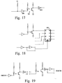
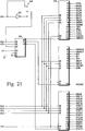
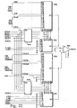
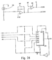
- Figs. 1 to 29B are the same as Figs. 1 to 34B of U.S. Patent no. 1,961,122, and a full description of those Figs. is provided in that Patent.
- FIGs. 30 and 31 depict a partial, longitudinal view of the opposite ends of a transurethral ablation catheter of the present invention.
- FIG. 32 is a cross-sectional view of the ablation catheter of FIG. 31 taken along the line 37-37.
- FIG. 33 is a partial, longitudinally sectioned view of the distal and intermediate portions of the ablation catheter of FIG. 31 taken along the line 38-38.
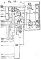
- FIG. 34 is a partial, longitudinally sectioned view of the proximal and intermediate portions of the ablation catheter of FIG. 30 taken along the line 39-39.
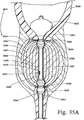
- FIG. 35A is a partial, longitudinal view of the transurethrally positioned ablation catheter of FIG. 30 for producing a non-cooled thermally conductive heat distribution in the prostate.
- FIG. 35B is a partial, longitudinal view of the transurethrally positioned ablation catheter of FIG. 35A for producing a thermally conductive heat distribution in the prostate and cooling the sphincters at the ends of the prostatic urethra.
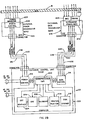
- FIG. 36 depicts an ablation system of the present invention for ablating tissue about the prostatic urethra.
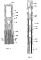
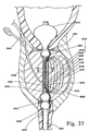
- FIG. 37 depicts a longitudinal view of another aspect of a transurethrally positioned ablation catheter of the present invention for ablating only prostatic tissue opposite the ejaculatory duct.
- FIG. 38 depicts a cross-sectional view of the transurethral ablation catheter of FIG. 37 taken along the line 43-43.
- FIGs. 39 and 40 depict portions of an alternative embodiment of the transurethral ablation catheter of the present invention having coaxial, telescopic members to position the catheter in the internal and external sphincters.
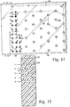
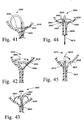
- FIGs. 41-45 depict alternative configurations for the distal fixation and cooling means of the transurethral ablation catheter of the present invention.
- FIGs. 30 and 31 Depicted in FIGs. 30 and 31 is a partial, longitudinal view of the opposite ends of transurethral ablation catheter 3501 having a thermally conductive heat-emitting element 3502 embedded near the distal end for producing a predetermined, thermally conductive heat distribution in prostatic tissue between the internal and external sphincters.
- This heat distribution ablates the prostatic urethra and the surrounding prostatic tissue.
- the diameter of the lumen through the prostatic tissue and urethra significantly increases, thereby advantageously increasing the flow of fluids therethrough.
- Transurethral ablation catheter 3501 also includes distal and proximal fixation and cooling balloons 3503 and 3504 that are inflatable for being positively secured about the internal and external urethral sphincters, respectively.
- the distal and proximal fixation balloons fix the longitudinal position of the catheter and heat-emitting element relative to the internal and external urethral sphincters. This reduces exposure of the sphincters to ablative temperatures emitted by the heat-emitting element.
- the sphincters are further protected from ablative temperatures by the circulation of a coolant through the interiors of the distal and proximal balloons during a transurethral ablation treatment.
- the transurethral ablation catheter is connected to a controller, described hereinafter, for controlling the power or energy supplied to the heat-emitting element and the coolant supplied to the interiors of the balloons.
- the controller is responsive to the temperatures sensed or measured by sensors positioned on the catheter for controlling the power or energy supplied to the catheter and the coolant supplied to the. balloons.
- the catheter produces and maintains a predetermined, thermally conductive heat distribution in the prostatic tissue to ablate the tissue without damaging the sphincter.
- Transurethral ablation catheter 3501 includes elongated member tube 3510 having proximal portion 3505, distal portion 3506, and intermediate portion 3507 extending therebetween.
- the intermediate portion is shaped and sized for intimate contact with the lining of the prostatic urethra.
- the intermediate portion of the transurethral ablation catheter includes heat-emitting element 3502, which is embedded in elongated member tube wall 3694.
- Distal portion 3506 includes distal fixation structure 3702 including distal fixation and cooling balloon 3503 for extending through the internal sphincter and into the bladder of a patient.
- the distal fixation structure also includes annular ring 3508 that is positioned about the circumference of the distal balloon for providing an annular recess in the balloon when inflated for positioning the internal sphincter of the patient therein.
- annular ring 3508 that is positioned about the circumference of the distal balloon for providing an annular recess in the balloon when inflated for positioning the internal sphincter of the patient therein.
- Proximal portion 3505 includes proximal fixation structure 3703 including proximal fixation and cooling balloon 3504 for extending through the external sphincter of a patient.
- the proximal fixation structure also includes annular ring 3509 that is positioned about the circumference of the proximal balloon for providing an annular recess in the balloon when inflated for positioning the external sphincter of the patient therein.
- the inflated proximal fixation and cooling balloon has a double toroidal shape for being fixedly positioned about the external sphincter, thereby also preventing proximal and distal migration of the catheter and subsequent exposure of the internal or external sphincters to ablative temperatures. Either one or both of the distal and proximal balloons maintains and fixedly positions the catheter longitudinally in the prostatic urethra of a patient.
- Elongated member tube 3510 is comprised of nylon, polytetrafluoroethylene, or another polymer material capable of withstanding ablation temperatures preferably in the range of 70-100°C.
- Transurethral ablation catheter 3501 has an outside diameter of approximately 18 French (6 mm or 0.236''). The catheter is sized for intimate contact with the urethra of a patient and is produced in various sizes ranging from 8 to 21 French to accommodate variations in individual patient anatomy.
- Transurethral ablation catheter 3501 also includes main longitudinal passageway 3684 approximately .036'' in diameter and extending entirely therethrough for extending a commercially available .034'' diameter wire guide 3511 therethrough.
- the wire guide is positioned to place the catheter in the urethra of a patient using a well-known procedure.
- Radiopaque ring 3512 is positioned about the distal end of the catheter tube and is circumferentially embedded in the surface thereof. The ring is visualized under fluoroscopy to place the distal end of the catheter in the urethra and bladder.
- Proximal portion 3505 and the proximal end of the transurethral ablation catheter is depicted in FIG. 31 with wire guide 3511 extending proximally therefrom.
- Well-known double-Y connector 3515 abuts proximal portion 3505 and is fixedly attached thereto by commercially available heat shrunk tube 3516.
- Double-Y connector 3515 includes side arm 3517 for housing single lumen tubes 3518-3521 that communicate with the catheter passageways leading to the interiors of the distal and proximal fixation and cooling balloons.
- the single lumen tubes include well-known female Luer lock connectors fixedly attached proximally thereto.
- the double-Y connector also includes side arm 3522 for containing temperature sensor and heat-emitting element lead wires.
- Temperature sensor lead wires comprise one common supply wire and three signal wires, one each for the three temperature sensors of the transurethral ablation catheter. Electrical ring connectors 3523-3528 are used for attaching each of the internal lead wires to other components of the ablation system via cables (not shown).
- Well-known single-Y connector 3529 abuts main arm 3685 of double-Y connector 3515 and is fixedly attached thereto by heat shrunk tube 3686.
- the single-Y connector includes main arm 3530 with a well-known internal seal for receiving wire guide 3511.
- the single-Y connector also includes side arm 3531 for attachment to drain tube 3532 for draining urine from the bladder to a waste receptacle (not shown).
- FIG. 32 Depicted in FIG. 32 is a cross-sectional view of elongated member tube 3510 of FIG. 31 taken along the line 37-37.
- Main longitudinal passageway 3684 extends the entire length of the catheter and is shown with the wire guide removed therefrom.
- Longitudinally extending balloon passageways 3680 and 3681 comprise supply means which communicate with the interior of distal fixation and cooling balloon 3503 for inflating the balloon and circulating a coolant therethrough.
- Longitudinally extending balloon passageways 3682 and 3683 also comprise supply means which communicate with the interior of proximal fixation and cooling balloon 3504 for inflating the balloon and circulating a coolant therethrough.
- the balloon passageways are at least 1 French (.3 mm) in diameter.
- Longitudinally extending passageway 3533 is approximately 1 French (.014'') in diameter and contains the approximately .006'' diameter, pair of insulated heat-emitting element lead wires 3534 and the four temperature sensor lead wires 3535.
- the lead wires need not be insulated, but are either embedded in the catheter wall or positioned in separate lumens.
- Longitudinal balloon passageways 3680 and 3681 are depicted as being diametrically opposed, as are longitudinal balloon passageways 3682 and 3683.
- longitudinal balloon passageways 3680-3683 and lead wire passageway 3533 are equally spaced about the circumference of the elongated member wall.
- Circulating coolant fluid through the interior of the balloon includes the use of one or more passageways and either the simultaneous or nonsimultaneous aspiration and irrigation of coolant fluid.
- FIG. 33 Depicted in FIG. 33 is a partial longitudinally sectioned view of the distal and intermediate portions 3506 and 3507 of transurethral ablation catheter 3501 of FIG. 30 taken along the line 38-38 with distal fixation and cooling balloon 3503 in an inflated state.
- Distal fixation balloon 3503 has a generally truncated conical shape for being fixedly positioned in the bladder neck and through the internal sphincter.
- Annular recess 3541 is formed in the inflated distal balloon by annular ring 3508 for positioning the internal sphincter therein.
- the distal fixation balloon is approximately 20 mm in length, 25 mm in diameter when inflated, and fixedly attached to the catheter tube by commercially available medical grade adhesive.
- the distal fixation balloon comprises, for example, a sheet of polyester material approximately 80 mm by 18 mm, which is affixed by a heat bond or a commercially available medical grade adhesive to another sheet of polyester material approximately 90 mm by 8 mm for providing the flared, conical shape.
- Annular ring 3508 comprises an elastic C-FLEXTM copolymer material ring having a rectangular cross-section for minimizing the cross-sectional diameter of the transurethral ablation catheter when the balloon is in a collapsed state. The annular ring is fixedly attached to the circumference of the collapsed balloon material by commercially available medical grade adhesive.
- the annular ring is friction fitted and comprises a ligature, a traditional O-ring, or a piece of tubing or cannula formed of a polymer material, a metal such as stainless steel, or a radiopaque material such as tantalum.
- Distal balloon 3503 is pushed against annular ring 3508 by the force of an inflation or coolant fluid on the interior of the balloon.
- the tolerance between the inside diameter of elongated member tube 3510 with the collapsed distal balloon material positioned therearound provides for the communication of fluid on either side of the annular ring in the interior of the distal balloon.
- the annular ring of the distal balloon is omitted, and the pressure applied by the internal sphincter forces the distal balloon into an appropriate shape such as a truncated conical shape or a double toroidal shape.
- Balloon passageways 3680 and 3681 extend longitudinally in wall 3694 of elongated member tube 3510 and communicate with the interior of the distal fixation and cooling balloon.
- Balloon passageway 3681 includes a plurality of aspiration ports 3536 for return fluid flow from the balloon interior on either side of the annular ring.
- Irrigation ports 3553-3556 of balloon passageway 3680 have different cross-sectional areas that gradually increase proximally by a factor of 8.6 percent. This graduated increase in area compensates for the otherwise variable flow rate of coolant from the longitudinal passageway, which would have been lower at the proximal end than at the distal end of the ports.
- the factor of 8.6 percent takes into consideration that the ports are each spaced approximately 4 mm apart.
- Coolant 3542 comprises a fluid such as sterile water, saline, or another fluid that is safe for injection into a patient. Coolant 3542 cools the internal sphincter and other tissue surrounding the distal fixation and cooling balloon to prevent thermal damage thereto.
- Radiopaque rings 3543 and 3513 are positioned about the circumference of the catheter tube and embedded in the surface thereof for visualizing under fluoroscopy annular recess 3541 and the distal end of heat-emitting element 3502.
- Temperature sensor 3544 is positioned on the catheter surface in the distal fixation balloon interior for sensing or measuring the temperature of the coolant therein.
- the temperature sensor is connected to the controller via a signal and a common lead wire for providing temperature information thereto.
- the controller uses the temperature information to control the flow rate and temperature of the coolant, which affects the predetermined, thermally conductive heat distribution produced in prostatic tissue.
- the coolant is circulated to maintain the temperature of the internal sphincter below a maximum of 40°C.
- Temperature sensor 3544 comprises a commercially available thermistor, but alternatively can comprise an optical fiber, thermocouple, or another commercially available temperature sensor.
- Main longitudinal passageway 3684 of the catheter provides for the irrigation and drainage of fluid to and from the bladder and for positioning the catheter over a wire guide during placement in a urethra.
- Heat-emitting element 3502 comprises a helically wound coil of .006'' diameter round wire such as nichrome, a nickel-chromium alloy, or another high resistance material. Alternatively, the coil is formed with wire having a rectangular cross-section. The wire comprises a biocompatible metal or a non-biocompatible metal that is coated with a biocompatible substance. The heat-emitting element is embedded in the elongated member tube wall during extrusion thereof. Heat-emitting element 3502 is approximately 3 to 4 cm in length, but can range from 2 to 6 cm to accommodate variations in individual patient anatomy.
- Heat-emitting element 3502 is welded to a pair of lead wires, which connect to a pair of ring connectors at the proximal end of the catheter as depicted in FIG. 31.
- Temperature sensor 3545 is embedded in the catheter and positioned centrally along the length of the heat-emitting element for sensing or measuring the temperature produced near the heat-emitting element.
- the temperature sensor is connected to the controller through a second signal lead wire and the common lead wire for providing temperature information about the heat-emitting element.
- the controller uses this temperature information to control the energy supplied to the heat-emitting element, thereby affecting the predetermined, thermally conductive heat distribution.
- FIG. 34 Depicted in FIG. 34 is a partial longitudinally sectioned view of the proximal and intermediate portions 3505 and 3507 of transurethral ablation catheter 3501 of FIG. 30 taken along the line 39-39 with proximal fixation and cooling balloon 3504 in an inflated state.
- Proximal balloon 3504 comprises a polyester material and is approximately 10 mm in length and 10 mm in diameter when inflated.
- the proximal fixation and cooling balloon is fixedly attached to the catheter tube by commercially available medical grade adhesive.
- Annular ring 3509 of the proximal balloon is similar to annular ring 3508 of the distal balloon and also comprises an elastic C-FLEXTM copolymer material ring having a rectangular cross-section.
- annular ring is fixedly attached to the circumference of the collapsed balloon material by commercially available medical grade adhesive.
- annular recess 3546 is formed by annular ring 3509 for positioning the external sphincter therein.
- the tolerance between the inside diameter of the annular ring and the outside diameter of elongated member tube wall 3694 with the collapsed balloon material positioned therearound provides for the communication of fluid on either side of the annular ring in the interior of the proximal fixation and cooling balloon.
- the annular ring of the proximal fixation balloon is omitted, and the pressure applied by the external sphincter forces the proximal balloon into a double toroidal shape.
- Balloon passageway 3682 and 3683 communicate with the interior of the proximal fixation and cooling balloon for inflating the balloon and circulating coolant 3542 in the interior of the balloon.
- Balloon passageway 3682 includes irrigation ports 3547-3550. Similar to irrigation ports 3553-3556 of longitudinal passageway 3681 of FIG. 33, the cross-sectional areas of irrigation ports 3547-3550 increase proximally by a factor of 8.6 percent for balancing the flow rate of coolant from longitudinal passageway 3682 into the balloon interior.
- Balloon passageway 3683 includes a plurality 3537 of aspiration ports for fluid flowing from the balloon interior on either side of the annular ring.
- Temperature sensor 3552 is positioned on the catheter surface in the interior of the proximal balloon for sensing or measuring the temperature of the coolant. This temperature information is provided to the controller through a third signal lead wire and the common lead wire in the same manner as temperature sensor 3544 of the distal fixation balloon depicted in FIG. 33.
- Radiopaque rings 3514 and 3551 are positioned about the circumference of the catheter tube and embedded in the surface thereof for visualizing under fluoroscopy the proximal end of heat-emitting element 3502 and annular recess 3546.
- radiopaque rings 3512-3514, 3543, and 3551 are completely embedded in the tube material.
- Radiopaque rings 3512-3514, 3543, and 3551 comprise a radiopaque material such as tantalum. Radiopaque stripes can be substituted for the rings.
- the outside surface of the catheter tube can be dimpled for improving the ultrasonic visualization of the catheter.
- a physician Prior to use of the transurethral ablation catheter, a physician uses a visualization means such as transrectal ultrasound to visualize the prostate gland, the prostatic urethra, and any obstructions. The physician also locates the internal and external sphincters to determine the length of the prostatic urethra, which extends therebetween.
- a transurethral ablation catheter with the appropriate distal and proximal fixation and cooling balloon spacing, heat-emitting element length, and elongated member tube diameter for making intimate contact with the lining of the prostatic urethra is then selected.
- a wire guide is inserted into the urethra of the patient, and a small catheter and dilation sheath are introduced into the urethra thereover.
- the treatment catheter When the urethra is sufficiently dilated, the treatment catheter is introduced over the wire guide and properly positioned in the urethra, as depicted in FIG. 35A.
- the ablation catheter is alternatively introduced into the prostatic urethra through a well-known introducer sheath.
- the physician can inject contrast medium through the main longitudinal passageway of the catheter to improve visualization.
- the distal and proximal fixation balloons are inflated for fixedly positioning the catheter with respect to the internal and external sphincters.
- a controlled power or energy source which is connected to the heat-emitting element, is activated for producing a predetermined, thermally conductive heat distribution in the prostatic tissue, as well as the prostatic urethra, between the sphincters.
- the heat distribution includes ablation temperatures preferably in the range of 70-100°C.
- the energized heat-emitting element produces this predetermined, thermally conductive heat distribution in the prostatic urethra and the adjacent prostate gland for ablating the tissue thereof and coagulating the blood vessels therein. Temperatures above 70°C cause coagulation. Temperatures from 45 to 70°C cause cell death (necrosis) and tissue sloughing for increasing the urethral diameter.
- Experiments with dogs have indicated that a 97°C ablative temperature applied to the prostatic urethra for a period of one hour causes coagulation and subsequent sloughing to enlarge satisfactorily the lumen through the prostate.
- Initial dog experiments indicated that ablative temperatures up to 80°C for a one hour period produced unsatisfactory results or did not enlarge the prostatic lumen sufficiently.
- a coolant is circulated through the interiors of the distal and proximal balloons for protecting the internal and external sphincters from these ablative temperatures.
- the distal and proximal balloons are collapsed, and the treatment catheter is removed from the urethra.
- ablation system 3676 for ablating tissue about the prostatic urethra utilizing the ablation catheter of the present invention.
- the system comprises transurethral ablation catheter 3501, controller 3678, controlled power or energy source 3679, and controlled, coolant circulating pump 3687.
- Catheter 3501 is positioned in the prostatic urethra of a patient and fixedly positioned therein by either one or both of distal and proximal fixation and cooling balloons 3503 and 3504, which respectively extend through the internal and external sphincters of the urethra. When so positioned, the energized catheter produces a predetermined, thermally conductive heat distribution in the prostatic tissue for ablating the tissue and enlarging the urethra.
- Controlled power or energy source 3679 supplies power or energy to the heat-emitting element, which is embedded in intermediate portion 3507 of the catheter.
- the source is connected to the heat-emitting element via cables, ring connectors, and lead wires represented by line 3692 for producing a predetermined temperature such as 97°C on the surface of intermediate catheter portion 3507.
- Thermistor 3545 is included with the intermediate portion of the catheter near the heat-emitting element thereof for providing temperature information to the controller via line 3697, which represents the lead wires, ring connector, and cable leading to the controller.
- the controller of the system responds to this temperature information by controlling the supply of power or energy as required to produce and maintain a predetermined temperature on the catheter surface and the predetermined, thermally conductive heat distribution in the prostatic tissue.
- Well-known controller 3678 includes a commercially available programmable microprocessor, such as the Motorola model MC68040, and a well-known control algorithm such as a proportional-integral-derivative, dead beat, or optimal control algorithm. Controller 3678 controls source 3679 and receives delivered power or energy via control line 3700.
- Distal and proximal fixation and cooling balloons 3503 and 3504 also cool the internal and external urethral sphincters to protect them from ablative temperatures.
- a coolant is circulated through the balloon interiors for cooling the balloons, the internal and external sphincters, and the tissue surrounding the sphincters. The temperature of the balloons, sphincters, and surrounding tissue is cooled to prevent the temperature from rising above 40°C.
- Pump 3687 is under the control of controller 3678 via control line 3696 and circulates coolant through the distal and proximal balloon interiors via single lumen tubes and respective pairs of longitudinal catheter balloon passageways represented by lines 3677, 3688 and 3690, 3695 for circulating or simultaneously irrigating and aspirating coolant fluid.
- Controlled, coolant circulating pump 3687 is a commercially available pump such as a centrifugal, diaphragm, or roller pump such as a Cole-Parmer MASTERFLEXTM roller pump.
- Thermistors 3544 and 3552 are positioned on the catheter surface in the respective distal and proximal balloons for providing temperature information to controller 3678 about the temperature of the coolant fluid in each balloon via lines 3698 and 3699, respectively. Each line represents the lead wires, ring connectors, and a cable connected to the controller.
- the controller responds to this information by controlling the pump to cool the sphincters below a maximum temperature and the power or energy source to produce and maintain the predetermined, thermally conductive heat distribution in the prostatic tissue.
- FIG. 35A Depicted in FIG. 35A is a partial longitudinal view of the transurethral ablation catheter 3501 with a partial cutaway view of heat-emitting element 3502 positioned in urethra 3557 and prostate 3558 of a patient for producing a non-cooled, predetermined, thermally conductive heat distribution 3571.
- Intermediate portion 3507 which includes heat-emitting element 3502, is positioned in intimate contact with the lining of the prostatic urethra 3560 and is maintained in a fixed longitudinal position therein by inflated distal fixation and cooling balloon 3503, which extends through internal sphincter 3561 and bladder neck 3563 into bladder 3559, and inflated proximal fixation and cooling balloon 3504, which extends through external sphincter 3562.
- the non-cooled heat distribution 3571 is produced in prostatic urethra 3560, prostatic tissue 3558, and surrounding tissue 3689 and includes isotherms 3564-3570. These isotherms represent static conditions in homogeneous tissue after the heat-emitting element has reached a steady state condition.
- Isotherm 3564 represents 37°C, which is approximately body temperature. The temperature of tissue increases gradually between isotherms. For example, the temperature of tissue between isotherms 3564 and 3565 increases to 40°C, which is indicated by isotherm 3565.
- Isotherms 3566, 3567, 3568, 3569, and 3570 respectively indicate 42°C, 47°C, 70°C, 92°C, and 97°C.
- Isotherm 3570 represents the surface temperature of the intermediate portion of the catheter. These isotherms represent the predetermined, thermally conductive heat distribution produced by the catheter in the surrounding tissue without the circulation of a coolant in the distal and proximal balloons. Without the circulation of a coolant, the internal and external sphincters are exposed to temperatures in the range from 40-47°C, which are considered unacceptable. Exposing the sphincters to temperatures ranging from 40-42°C over a period of time such as one hour likely damages the nerves and muscles of the sphincters. Exposure to temperatures ranging from 42-47°C over a period of time such as one hour causes cell death and sloughing of cells. Exposure to temperatures ranging from 47-70°C and above effects certain and rapid cell death or necrosis, sloughing, and coagulation of blood vessels.
- FIG. 35B Depicted in FIG. 35B is a partial longitudinal view of transurethral ablation catheter 3501 of FIG. 35A and another predetermined, thermally conductive heat distribution 3572 produced in prostatic urethra 3560, prostate 3558, and surrounding tissue 3689. Heat distribution 3572 is produced as a result of circulating a coolant through fixation and cooling balloons 3503 and 3504. Cooled, thermally conductive heat distribution 3572 includes isotherms 3570 and 3573-3578. Isotherm 3573 represents 37°C, which is approximately body temperature.
- Isotherm 3570 represents the surface temperature of the intermediate portion of the catheter.
- the isotherms of this heat distribution indicate that temperatures above body temperature are not thermally conducted near the sphincters or tissue surrounding the sphincters.
- the sphincters and several millimeters of surrounding tissue lie outside isotherm 3573, which indicates an approximate body temperature, during an ablative treatment including the circulation of coolant.
- FIG. 37 Depicted in FIG. 37 is a longitudinal view of another aspect of the present invention, transurethral ablation catheter 3624 positioned in urethra 3557 and prostate 3558 of a patient.
- intermediate portion 3626 which includes heat-emitting element 3625, is fixedly positioned in prostatic urethra 3560 by inflated distal and proximal fixation and cooling balloons 3627 and 3628, which respectively extend through the internal and external sphincters 3561 and 3562.
- heat-emitting element 3625 of this alternative catheter extends only partially around the circumference of the catheter for selectively heating a portion of the prostate, for example, the portion of the prostate opposite ejaculatory duct 3629 which empties seminal vesicles 3630 into the prostatic urethra. It is thought that avoiding ablative temperatures about the seminal vesicles and ejaculatory duct minimizes the risk of complications such as impotence and infertility.
- the heat-emitting element comprises a metal wire formed into a serpentine configuration.
- the serpentine-shaped heat-emitting element is embedded semicircularly in the catheter wall, as depicted in FIG. 38.
- Semicircular radiopaque rings 3631 and 3632 are embedded in the surface of the catheter and positioned at each end of the heat-emitting element for visualizing the longitudinal and circumferential position of the heat-emitting element, which produces a third predetermined, thermally conductive heat distribution in the prostatic urethra and surrounding tissue.
- Thermally conductive heat distribution 3633 produced by catheter 3624 is depicted with circulation of a coolant through the interiors of the distal and proximal fixation and cooling balloons 3627 and 3628.
- the coolant fluid is circulated through longitudinal passageway 3641 with medial septum 3642, as depicted in FIG. 38, for cooling that portion of the catheter and the prostatic tissue facing away from the heat-emitting element.
- the cooled, predetermined, thermally conductive heat distribution produced by this catheter is represented by isotherms 3634-3640.
- Isotherm 3634 represents 37°C, which is approximately body temperature
- isotherms 3635-3639 respectively represent 40°C, 42°C, 47°C, 70°C, and 92°C.
- Isotherm 3640 represents 97°C, which is the surface temperature of the catheter. These isotherms indicate that temperatures above body temperature are not thermally conducted near the sphincters or tissue surrounding the sphincters. Furthermore, body tissue on the cooling side of the catheter, or the side of the catheter facing away from the heat-emitting element and toward the ejaculatory duct and seminal vesicles, remains at or near body temperature.
- FIG. 38 Depicted in FIG. 38 is a cross-sectional view of transurethral ablation catheter 3624 of FIG. 37 taken along the line 43-43.
- Longitudinal passageway 3641 with medial septum 3642 provides for the irrigation of coolant on outer side 3644 and the aspiration of coolant on inner side 3643.
- Main longitudinal passageway 3645 provides for the irrigation and drainage of fluid from the bladder and for the placement of the catheter over a wire guide in a well-known manner.
- Longitudinal balloon passageways 3646 and 3647 provide for the respective irrigation and aspiration of coolant to the interior of the distal balloon of the catheter.
- Longitudinal passageway 3648 contains the lead wires of heat-emitting element 3625 and the distal and intermediate portion temperature sensors.
- transurethral ablation catheter 3701 which is an enhancement to the catheter of the present invention, for producing a predetermined, thermally conductive heat distribution in prostatic tissue.
- the catheter comprises inner and outer coaxial members 3538 and 3539, respectively, positioned in telescopic relation to each other. The relative telescopic position of the inner and outer coaxial catheters can be varied to provide different spacing 3704 between the fixation and cooling balloons to accommodate the different prostatic urethral lengths of patients.
- Inner member 3538 comprises elongated member tube 3592 and includes distal and intermediate portions 3579 and 3580, which are in an inflated state and comparable to the distal and intermediate portions of the transurethral ablation catheter of FIG. 33.
- Distal portion 3579 of the inner member includes distal fixation and cooling balloon 3540 for extending through the internal sphincter and into the bladder of a patient.
- Distal balloon 3540 is fixedly attached to the member by commercially available medical grade adhesive.
- Annular ring 3581 is fixedly attached about the circumference of the distal balloon for providing annular recess 3582 for positioning the internal sphincter therein.
- Longitudinally extending balloon passageways 3583 and 3584 communicate with the interior of distal fixation and cooling balloon 3540 for aspirating and irrigating coolant 3693 therethrough so that the inflated distal fixation and cooling balloon, internal sphincter, and surrounding tissue are cooled.
- Balloon passageway 3583 includes a plurality 3593 of aspiration ports.
- Balloon passageway 3584 includes plurality 3594 of irrigation ports, which vary in size in a manner similar to the irrigation ports of the catheter of FIG. 33.
- Temperature sensor 3585 is positioned on the surface of the inner member in the interior of the distal balloon for sensing or measuring the temperature of the coolant thereabout.
- the distal portion of the inner member also includes radiopaque rings 3586-3588 for visualizing under fluoroscopy the distal end of the member, the location of the internal sphincter when the catheter is positioned in a urethra, and the distal end of the heat-emitting element, respectively.
- Inner member 3538 further includes main longitudinal passageway 3589 for introducing the catheter over a wire guide and for irrigating and draining the bladder.
- Intermediate portion 3580 of the inner member includes heat-emitting element 3590, which is embedded in the wall of the member for heating the prostatic urethra and tissue and temperature sensor 3591, which is positioned in the inner member in a central location along the length of the heat-emitting element for sensing or measuring the temperature thereof.
- Outer member 3539 comprises elongated member tube 3607 and includes proximal portion 3595, which is comparable to the proximal portion of the transurethral ablation catheter of FIG. 34.
- Outer member 3539 includes proximal fixation and cooling balloon 3596 for extending through the external sphincter of a patient.
- Proximal balloon 3596 is fixedly attached to the member by commercially available medical grade adhesive.
- Annular ring 3597 is fixedly attached about the circumference of the inflated proximal balloon for providing annular recess 3598 in the balloon for positioning the external sphincter therein.
- Balloon passageway 3599 and 3600 communicate with the interior of proximal fixation and cooling balloon 3596 for circulating coolant 3693 therethrough so that the proximal balloon, external sphincter, and surrounding tissue are cooled.
- Balloon passageway 3599 includes plurality 3601 of aspiration ports.
- Balloon passageway 3600 includes plurality 3602 of irrigation ports which are graduated in cross-sectional area in a manner similar to that of the irrigation ports of the catheter of FIG. 33.
- Temperature sensor 3603 is positioned on the surface of the outer member in the interior of the proximal fixation and cooling balloon for sensing or measuring the temperature of the coolant.
- the distal portion of the outer member also includes radiopaque rings 3604 and 3605 for visualizing under fluoroscopy the distal end of the proximal fixation and cooling balloon and annular recess 3598 for positioning the external sphincter therein.
- Outer member 3539 further includes main longitudinal passageway 3606 for telescopically positioning the inner member therein.
- Proximal portion 3608 of the outer member includes well-known double-Y connector 3609 with side arm 3610 for containing a plurality 3613 of proximal balloon, single lumen tubes and side arm 3611 for containing the heat-emitting element and temperature sensor lead wires.
- Each of the lead wires is interiorly attached to one of plurality 3612 of ring connectors.
- Double-Y connector 3609 is fixedly attached to the outer member using heat shrunk tube 3614.
- Proximal portion 3615 of the inner member includes well-known triple side arm connector 3616 with side arms 3617 and 3618 for containing a plurality 3619 of distal balloon, single lumen tubes and a plurality of temperature sensor lead wires, respectively.
- Each of the temperature sensor lead wires is interiorly attached to one of plurality 3620 of ring connectors.
- Temperature information from the temperature sensors positioned in each balloon and near the heat-emitting element is provided via the lead wires and ring connectors to the controller.
- the controller in response controls the supply of power or energy to the heat-emitting element for producing the predetermined, thermally conductive heat distribution in prostatic tissue.
- Triple side arm connector 3616 also includes side arm 3621 for irrigating and draining the bladder through drainage tube 3622 and main arm 3623 for inserting wire guide 3511 therethrough and into the catheter.
- Triple side arm connector 3616 is fixedly attached to the inner member via main port 3685 of double-Y connector 3609 and heat shrunk tube 3691.
- the coaxial members are slidably movable and fixedly positionable relative to each other via well-known rotatable locking collar hub 3705. The longitudinal position of the coaxial members can be varied for providing different spacing 3704 between the distal and proximal fixation balloons, thereby accommodating variations in individual patient anatomy.
- FIGs. 41-45 Depicted in FIGs. 41-45 are alternative configurations for the distal fixation and cooling means of the transurethral ablation catheter of the present invention for preventing removal of the distal portion of the catheter from bladder 3559 of a patient.
- These configurations can be actuated by introducing the distal portion of a transurethral ablation catheter through an outer introducer sheath in a well-known manner.
- the preformed alternative configuration of the distal catheter end assumes its preformed shape.
- the circulation of a coolant is accomplished via a passageway in the wall of any of the fixation means. In the case of a pigtail, for example, coolant is circulated through a continuous passageway in the spiral.
- modified pigtail 3649 includes a plurality 3652 of side ports for facilitating irrigation to and drainage from the bladder.
- longitudinally oriented pigtail 3553 of distal portion 3554 includes plurality 3556 of side ports for facilitating irrigation to and drainage from the bladder.
- distal portion 3660 Depicted in FIG. 43 is plurality of tines 3657-3659 of distal portion 3660.
- distal portion 3660 includes plurality 3662 of side ports for facilitating irrigation to and drainage from the bladder.
- FIG. 44 Depicted in FIG. 44 is another alternative configuration for the distal fixation and cooling means of the transurethral ablation catheter in the form of well-known malecot 3663 having a plurality of wings or strips 3664-3667 for positively preventing removal of distal portion 3668 of the catheter from bladder 3559 of a patient. Drainage port 3669 of the catheter is positioned at the base of the plurality of strips. The malecot is actuated by pulling cable 3670 proximally for bringing the wings or strips into contact with the bladder.
- FIG. 45 Depicted in FIG. 45 is yet another alternative configuration for the distal fixation and cooling means of the transurethral ablation catheter in the form of articulating T-tube 3671 with pivot pin 3672 for actuating the distal end 3673 of the tube proximally and preventing removal of distal portion 3674 of the catheter from bladder 3559 of a patient.
- Distal end 3673 of the T-tube includes end port 3675 for the irrigation and drainage of fluids to and from the bladder.
- the distal fixation and cooling balloon can comprise any of a number of other known fixation and cooling means for securing the distal end of the catheter in the bladder.
- the proximal fixation and cooling device can also be a pair of inflatable balloons, rather than one balloon with a toroidal shape.
- the distal fixation and cooling balloon can be round in shape rather than conical.
- the transurethral ablation catheter can include pressure transducers, pH sensors, electro myogram electrodes, and other sensors to monitor the treatment and ensure safety and effectiveness. Ridges can be placed circumferentially around the catheter at either end of the heat-emitting element for facilitating tactile positioning of the heat-emitting element.
- Separate cooling balloons or structures are also contemplated in addition to or in place of the fixation balloons. It is also contemplated that cooling to one or more fixation and/or cooling means can be accomplished with one or more longitudinally extending passageways. Irrigation and aspiration are alternatingly performed with one passageway to facilitate cooling of the sphincters. With separate distal and proximal cooling means, one can be aspirated while the other is simultaneously or alternatingly irrigated. It is also contemplated that only one fixation and cooling structure is needed to fixedly position the catheter both distally and proximally in the internal and external sphincters.
Applications Claiming Priority (2)
| Application Number | Priority Date | Filing Date | Title |
|---|---|---|---|
| US07/823,318 US5304214A (en) | 1992-01-21 | 1992-01-21 | Transurethral ablation catheter |
| US823318 | 1992-01-21 |
Publications (3)
| Publication Number | Publication Date |
|---|---|
| EP0552934A2 true EP0552934A2 (de) | 1993-07-28 |
| EP0552934A3 EP0552934A3 (en) | 1993-10-20 |
| EP0552934B1 EP0552934B1 (de) | 2000-06-14 |
Family
ID=25238417
Family Applications (1)
| Application Number | Title | Priority Date | Filing Date |
|---|---|---|---|
| EP93300381A Expired - Lifetime EP0552934B1 (de) | 1992-01-21 | 1993-01-20 | Transurethraler Katheter zur Ablation |
Country Status (4)
| Country | Link |
|---|---|
| US (1) | US5304214A (de) |
| EP (1) | EP0552934B1 (de) |
| CA (1) | CA2087623A1 (de) |
| DE (1) | DE69328842T2 (de) |
Cited By (5)
| Publication number | Priority date | Publication date | Assignee | Title |
|---|---|---|---|---|
| EP0713712A1 (de) * | 1994-11-23 | 1996-05-29 | Medinol Limited | Ballonkatheter |
| WO1996027406A1 (en) * | 1995-03-07 | 1996-09-12 | American Medical Systems, Inc. | Slowly dilating device for the urethra |
| WO1997016218A1 (en) * | 1995-11-02 | 1997-05-09 | Overtoom Timotheus Theodorus C | System or apparatus for treating the ureter and/or pyelo-ureter junction |
| EP0904030A1 (de) * | 1996-05-03 | 1999-03-31 | Urologix, Inc. | Axiale thermotherapie |
| EP1709922A1 (de) * | 2004-01-06 | 2006-10-11 | Toray Industries, Inc. | Ballonkatheter |
Families Citing this family (232)
| Publication number | Priority date | Publication date | Assignee | Title |
|---|---|---|---|---|
| US5542915A (en) | 1992-08-12 | 1996-08-06 | Vidamed, Inc. | Thermal mapping catheter with ultrasound probe |
| US5435805A (en) | 1992-08-12 | 1995-07-25 | Vidamed, Inc. | Medical probe device with optical viewing capability |
| US5370675A (en) | 1992-08-12 | 1994-12-06 | Vidamed, Inc. | Medical probe device and method |
| US5421819A (en) | 1992-08-12 | 1995-06-06 | Vidamed, Inc. | Medical probe device |
| US5413588A (en) * | 1992-03-06 | 1995-05-09 | Urologix, Inc. | Device and method for asymmetrical thermal therapy with helical dipole microwave antenna |
| US5720718A (en) | 1992-08-12 | 1998-02-24 | Vidamed, Inc. | Medical probe apparatus with enhanced RF, resistance heating, and microwave ablation capabilities |
| US5456662A (en) | 1993-02-02 | 1995-10-10 | Edwards; Stuart D. | Method for reducing snoring by RF ablation of the uvula |
| US5514131A (en) | 1992-08-12 | 1996-05-07 | Stuart D. Edwards | Method for the ablation treatment of the uvula |
| US5672153A (en) | 1992-08-12 | 1997-09-30 | Vidamed, Inc. | Medical probe device and method |
| US5630794A (en) | 1992-08-12 | 1997-05-20 | Vidamed, Inc. | Catheter tip and method of manufacturing |
| US5470308A (en) | 1992-08-12 | 1995-11-28 | Vidamed, Inc. | Medical probe with biopsy stylet |
| US5556377A (en) | 1992-08-12 | 1996-09-17 | Vidamed, Inc. | Medical probe apparatus with laser and/or microwave monolithic integrated circuit probe |
| US5720719A (en) | 1992-08-12 | 1998-02-24 | Vidamed, Inc. | Ablative catheter with conformable body |
| US6537306B1 (en) * | 1992-11-13 | 2003-03-25 | The Regents Of The University Of California | Method of manufacture of a transurethral ultrasound applicator for prostate gland thermal therapy |
| DE4310923C2 (de) * | 1993-04-02 | 1996-10-31 | Siemens Ag | Therapieeinrichtung zur Behandlung von pathologischem Gewebe mit einem Katheter |
| CA2164860C (en) * | 1993-06-10 | 2005-09-06 | Mir A. Imran | Transurethral radio frequency ablation apparatus |
| US5464437A (en) * | 1993-07-08 | 1995-11-07 | Urologix, Inc. | Benign prostatic hyperplasia treatment catheter with urethral cooling |
| US5599345A (en) * | 1993-11-08 | 1997-02-04 | Zomed International, Inc. | RF treatment apparatus |
| US5928229A (en) | 1993-11-08 | 1999-07-27 | Rita Medical Systems, Inc. | Tumor ablation apparatus |
| US6071280A (en) | 1993-11-08 | 2000-06-06 | Rita Medical Systems, Inc. | Multiple electrode ablation apparatus |
| US5967976A (en) * | 1994-08-19 | 1999-10-19 | Novoste Corporation | Apparatus and methods for procedures related to the electrophysiology of the heart |
| US5529067A (en) * | 1994-08-19 | 1996-06-25 | Novoste Corporation | Methods for procedures related to the electrophysiology of the heart |
| US5814029A (en) * | 1994-11-03 | 1998-09-29 | Daig Corporation | Guiding introducer system for use in ablation and mapping procedures in the left ventricle |
| US5735280A (en) * | 1995-05-02 | 1998-04-07 | Heart Rhythm Technologies, Inc. | Ultrasound energy delivery system and method |
| US6187346B1 (en) | 1995-06-07 | 2001-02-13 | Ablation Products, Inc. | Intrauterine chemical cauterizing method and composition |
| DE69638173D1 (de) | 1995-06-07 | 2010-06-10 | Robert S Neuwirth | Verfahren und mittel zur intrauterinen nekrosierung |
| US6780180B1 (en) | 1995-06-23 | 2004-08-24 | Gyrus Medical Limited | Electrosurgical instrument |
| US6293942B1 (en) | 1995-06-23 | 2001-09-25 | Gyrus Medical Limited | Electrosurgical generator method |
| EP0771176B2 (de) | 1995-06-23 | 2006-01-04 | Gyrus Medical Limited | Elektrochirurgisches instrument |
| US6015406A (en) | 1996-01-09 | 2000-01-18 | Gyrus Medical Limited | Electrosurgical instrument |
| CA2224975A1 (en) | 1995-06-23 | 1997-01-09 | Gyrus Medical Limited | An electrosurgical instrument |
| US5843144A (en) * | 1995-06-26 | 1998-12-01 | Urologix, Inc. | Method for treating benign prostatic hyperplasia with thermal therapy |
| US6080150A (en) | 1995-08-15 | 2000-06-27 | Rita Medical Systems, Inc. | Cell necrosis apparatus |
| US5925042A (en) | 1995-08-15 | 1999-07-20 | Rita Medical Systems, Inc. | Multiple antenna ablation apparatus and method |
| US5913855A (en) | 1995-08-15 | 1999-06-22 | Rita Medical Systems, Inc. | Multiple antenna ablation apparatus and method |
| US6689127B1 (en) * | 1995-08-15 | 2004-02-10 | Rita Medical Systems | Multiple antenna ablation apparatus and method with multiple sensor feedback |
| US6090105A (en) | 1995-08-15 | 2000-07-18 | Rita Medical Systems, Inc. | Multiple electrode ablation apparatus and method |
| US6132425A (en) | 1995-08-15 | 2000-10-17 | Gough; Edward J. | Cell necrosis apparatus |
| US6059780A (en) | 1995-08-15 | 2000-05-09 | Rita Medical Systems, Inc. | Multiple antenna ablation apparatus and method with cooling element |
| US5951547A (en) | 1995-08-15 | 1999-09-14 | Rita Medical Systems, Inc. | Multiple antenna ablation apparatus and method |
| US5980517A (en) | 1995-08-15 | 1999-11-09 | Rita Medical Systems, Inc. | Cell necrosis apparatus |
| US20060271091A1 (en) * | 1995-09-18 | 2006-11-30 | Campbell Carey V | Balloon catheter device |
| US5868704A (en) * | 1995-09-18 | 1999-02-09 | W. L. Gore & Associates, Inc. | Balloon catheter device |
| US6428538B1 (en) | 1995-10-20 | 2002-08-06 | United States Surgical Corporation | Apparatus and method for thermal treatment of body tissue |
| US5837001A (en) * | 1995-12-08 | 1998-11-17 | C. R. Bard | Radio frequency energy delivery system for multipolar electrode catheters |
| US6090106A (en) | 1996-01-09 | 2000-07-18 | Gyrus Medical Limited | Electrosurgical instrument |
| US6013076A (en) | 1996-01-09 | 2000-01-11 | Gyrus Medical Limited | Electrosurgical instrument |
| US6016452A (en) * | 1996-03-19 | 2000-01-18 | Kasevich; Raymond S. | Dynamic heating method and radio frequency thermal treatment |
| US6047216A (en) * | 1996-04-17 | 2000-04-04 | The United States Of America Represented By The Administrator Of The National Aeronautics And Space Administration | Endothelium preserving microwave treatment for atherosclerosis |
| US6565561B1 (en) | 1996-06-20 | 2003-05-20 | Cyrus Medical Limited | Electrosurgical instrument |
| GB9612993D0 (en) | 1996-06-20 | 1996-08-21 | Gyrus Medical Ltd | Electrosurgical instrument |
| GB2314274A (en) | 1996-06-20 | 1997-12-24 | Gyrus Medical Ltd | Electrode construction for an electrosurgical instrument |
| US20040220455A1 (en) * | 1996-06-26 | 2004-11-04 | Lowe Robert I. | Method for monitoring blood characteristics and cardiopulmonary function |
| US6106475A (en) * | 1996-06-26 | 2000-08-22 | Tobo, Llc | Device for use in temporary insertion of a sensor within a patient's body |
| US6231514B1 (en) | 1996-06-26 | 2001-05-15 | Tobo, Llc | Device for use in temporary insertion of a sensor within a patient's body |
| US6106521A (en) * | 1996-08-16 | 2000-08-22 | United States Surgical Corporation | Apparatus for thermal treatment of tissue |
| US5792070A (en) * | 1996-08-30 | 1998-08-11 | Urologix, Inc. | Rectal thermosensing unit |
| US5730134A (en) * | 1996-09-09 | 1998-03-24 | General Electric Company | System to monitor temperature near an invasive device during magnetic resonance procedures |
| US8353908B2 (en) | 1996-09-20 | 2013-01-15 | Novasys Medical, Inc. | Treatment of tissue in sphincters, sinuses, and orifices |
| GB9626512D0 (en) | 1996-12-20 | 1997-02-05 | Gyrus Medical Ltd | An improved electrosurgical generator and system |
| US5891457A (en) * | 1997-05-12 | 1999-04-06 | Neuwirth; Robert S. | Intrauterine chemical necrosing method, composition, and apparatus |
| US5938660A (en) * | 1997-06-27 | 1999-08-17 | Daig Corporation | Process and device for the treatment of atrial arrhythmia |
| US6251109B1 (en) | 1997-06-27 | 2001-06-26 | Daig Corporation | Process and device for the treatment of atrial arrhythmia |
| US6139571A (en) * | 1997-07-09 | 2000-10-31 | Fuller Research Corporation | Heated fluid surgical instrument |
| US9023031B2 (en) * | 1997-08-13 | 2015-05-05 | Verathon Inc. | Noninvasive devices, methods, and systems for modifying tissues |
| US6123083A (en) * | 1997-08-29 | 2000-09-26 | Urologix, Inc. | Device and method for treatment of a prostate while preventing urethral constriction due to collagen rich tissue shrinkage |
| US5995875A (en) * | 1997-10-01 | 1999-11-30 | United States Surgical | Apparatus for thermal treatment of tissue |
| US5957901A (en) * | 1997-10-14 | 1999-09-28 | Merit Medical Systems, Inc. | Catheter with improved spray pattern for pharmaco-mechanical thrombolysis therapy |
| AU2114299A (en) * | 1998-01-14 | 1999-08-02 | Conway-Stuart Medical, Inc. | Electrosurgical device for sphincter treatment |
| US6440127B2 (en) | 1998-02-11 | 2002-08-27 | Cosman Company, Inc. | Method for performing intraurethral radio-frequency urethral enlargement |
| US6517534B1 (en) | 1998-02-11 | 2003-02-11 | Cosman Company, Inc. | Peri-urethral ablation |
| GB9807303D0 (en) | 1998-04-03 | 1998-06-03 | Gyrus Medical Ltd | An electrode assembly for an electrosurgical instrument |
| US6716236B1 (en) | 1998-04-21 | 2004-04-06 | Alsius Corporation | Intravascular catheter with heat exchange element having inner inflation element and methods of use |
| US6368304B1 (en) | 1999-02-19 | 2002-04-09 | Alsius Corporation | Central venous catheter with heat exchange membrane |
| US6419643B1 (en) * | 1998-04-21 | 2002-07-16 | Alsius Corporation | Central venous catheter with heat exchange properties |
| US6126684A (en) * | 1998-04-21 | 2000-10-03 | The Regents Of The University Of California | Indwelling heat exchange catheter and method of using same |
| US6338727B1 (en) | 1998-08-13 | 2002-01-15 | Alsius Corporation | Indwelling heat exchange catheter and method of using same |
| US8128595B2 (en) | 1998-04-21 | 2012-03-06 | Zoll Circulation, Inc. | Method for a central venous line catheter having a temperature control system |
| US6216703B1 (en) * | 1998-05-08 | 2001-04-17 | Thermatrx, Inc. | Therapeutic prostatic thermotherapy |
| US6112123A (en) * | 1998-07-28 | 2000-08-29 | Endonetics, Inc. | Device and method for ablation of tissue |
| US6673098B1 (en) * | 1998-08-24 | 2004-01-06 | Radiant Medical, Inc. | Disposable cassette for intravascular heat exchange catheter |
| US6122551A (en) * | 1998-12-11 | 2000-09-19 | Urologix, Inc. | Method of controlling thermal therapy |
| US6146411A (en) | 1998-12-24 | 2000-11-14 | Alsius Corporation | Cooling system for indwelling heat exchange catheter |
| US6299599B1 (en) * | 1999-02-19 | 2001-10-09 | Alsius Corporation | Dual balloon central venous line catheter temperature control system |
| US6582398B1 (en) * | 1999-02-19 | 2003-06-24 | Alsius Corporation | Method of managing patient temperature with a heat exchange catheter |
| US6019783A (en) * | 1999-03-02 | 2000-02-01 | Alsius Corporation | Cooling system for therapeutic catheter |
| US6161049A (en) * | 1999-03-26 | 2000-12-12 | Urologix, Inc. | Thermal therapy catheter |
| US6939346B2 (en) | 1999-04-21 | 2005-09-06 | Oratec Interventions, Inc. | Method and apparatus for controlling a temperature-controlled probe |
| EP1180004A1 (de) * | 1999-05-18 | 2002-02-20 | Silhouette Medical Inc. | Chirurgische vorrichtung zur gewichtskontrolle |
| US6272384B1 (en) | 1999-05-27 | 2001-08-07 | Urologix, Inc. | Microwave therapy apparatus |
| US6470204B1 (en) * | 1999-08-25 | 2002-10-22 | Egidijus Edward Uzgiris | Intracavity probe for MR image guided biopsy and delivery of therapy |
| US6685734B1 (en) | 1999-12-17 | 2004-02-03 | Linvatec Biomaterials Oy | Urethral stent delivery system |
| US6599237B1 (en) | 2000-01-10 | 2003-07-29 | Errol O. Singh | Instrument and method for facilitating endoscopic examination and surgical procedures |
| US6312391B1 (en) * | 2000-02-16 | 2001-11-06 | Urologix, Inc. | Thermodynamic modeling of tissue treatment procedure |
| US6368147B1 (en) * | 2000-03-02 | 2002-04-09 | Microhelix, Inc. | Zero insertion force percutaneous connector and flexible brain probe assembly |
| WO2001076517A2 (en) | 2000-04-07 | 2001-10-18 | The General Hospital Corporation D/B/A Massachusetts General Hospital | Methods and apparatus for thermally affecting tissue |
| US7306591B2 (en) | 2000-10-02 | 2007-12-11 | Novasys Medical, Inc. | Apparatus and methods for treating female urinary incontinence |
| CA2425061A1 (en) * | 2000-10-05 | 2002-04-11 | Seacoast Technologies, Inc. | Neurosurgical device for thermal therapy |
| US20040034321A1 (en) * | 2000-10-05 | 2004-02-19 | Seacoast Technologies, Inc. | Conformal pad for neurosurgery and method thereof |
| US6530945B1 (en) | 2000-11-28 | 2003-03-11 | Alsius Corporation | System and method for controlling patient temperature |
| US6529775B2 (en) | 2001-01-16 | 2003-03-04 | Alsius Corporation | System and method employing indwelling RF catheter for systemic patient warming by application of dielectric heating |
| US6743226B2 (en) | 2001-02-09 | 2004-06-01 | Cosman Company, Inc. | Adjustable trans-urethral radio-frequency ablation |
| US6451045B1 (en) | 2001-02-22 | 2002-09-17 | Alsius Corporation | Heat exchange catheter having a helically wrapped heat exchanger |
| US6497704B2 (en) | 2001-04-04 | 2002-12-24 | Moshe Ein-Gal | Electrosurgical apparatus |
| US6641602B2 (en) | 2001-04-13 | 2003-11-04 | Alsius Corporation | Method and device including a colo-rectal heat exchanger |
| US6752786B2 (en) * | 2001-05-31 | 2004-06-22 | Radiant Medical, Inc. | Moving heat exchange catheter system |
| WO2003039389A1 (en) * | 2001-11-06 | 2003-05-15 | Imadent Ltd. | Systems for ascertaining proximity of an oral surgical instrument to a mandibular canal and methods of protecting a mandibular canal from damage during an oral surgical procedure |
| US6894456B2 (en) * | 2001-11-07 | 2005-05-17 | Quallion Llc | Implantable medical power module |
| US7179219B2 (en) | 2001-11-20 | 2007-02-20 | Ams Research Corporation | Incontinence treatment with urethral guide |
| US6685623B2 (en) | 2001-11-20 | 2004-02-03 | Surx, Inc. | Incontinence treatment with urethral guide |
| US6572640B1 (en) | 2001-11-21 | 2003-06-03 | Alsius Corporation | Method and apparatus for cardiopulmonary bypass patient temperature control |
| US6746465B2 (en) * | 2001-12-14 | 2004-06-08 | The Regents Of The University Of California | Catheter based balloon for therapy modification and positioning of tissue |
| EP1465701A4 (de) | 2002-01-15 | 2008-08-13 | Univ California | System und verfahren zur direktionalen ultraschalltherapie an gelenkigen verbindungen |
| US20050124898A1 (en) * | 2002-01-16 | 2005-06-09 | Ep Medsystems, Inc. | Method and apparatus for isolating a catheter interface |
| US7648462B2 (en) | 2002-01-16 | 2010-01-19 | St. Jude Medical, Atrial Fibrillation Division, Inc. | Safety systems and methods for ensuring safe use of intra-cardiac ultrasound catheters |
| EP1503685B1 (de) | 2002-01-23 | 2012-10-31 | The Regents of The University of California | Implantierbares thermisches behandlungsgerät |
| US7003356B2 (en) * | 2002-03-08 | 2006-02-21 | Quallion Llc | Battery terminal sealing and supporting device and method |
| US8328877B2 (en) * | 2002-03-19 | 2012-12-11 | Boston Scientific Scimed, Inc. | Stent retention element and related methods |
| US6866662B2 (en) * | 2002-07-23 | 2005-03-15 | Biosense Webster, Inc. | Ablation catheter having stabilizing array |
| US7118531B2 (en) | 2002-09-24 | 2006-10-10 | The Johns Hopkins University | Ingestible medical payload carrying capsule with wireless communication |
| US7258690B2 (en) | 2003-03-28 | 2007-08-21 | Relievant Medsystems, Inc. | Windowed thermal ablation probe |
| US8361067B2 (en) | 2002-09-30 | 2013-01-29 | Relievant Medsystems, Inc. | Methods of therapeutically heating a vertebral body to treat back pain |
| US6907884B2 (en) | 2002-09-30 | 2005-06-21 | Depay Acromed, Inc. | Method of straddling an intraosseous nerve |
| US6716176B1 (en) | 2002-09-30 | 2004-04-06 | Tobo, Llc | Device for use in temporary insertion of a sensor within a patient's body |
| US7010337B2 (en) * | 2002-10-24 | 2006-03-07 | Furnary Anthony P | Method and apparatus for monitoring blood condition and cardiopulmonary function |
| US7278984B2 (en) * | 2002-12-31 | 2007-10-09 | Alsius Corporation | System and method for controlling rate of heat exchange with patient |
| US7223266B2 (en) | 2003-02-04 | 2007-05-29 | Cardiodex Ltd. | Methods and apparatus for hemostasis following arterial catheterization |
| CN2885311Y (zh) | 2006-01-18 | 2007-04-04 | 郑成福 | 经尿道光动力疗法前列腺治疗仪 |
| US20040199086A1 (en) * | 2003-04-03 | 2004-10-07 | Crisp William E. | Urinary tract catheter |
| US7101387B2 (en) * | 2003-04-30 | 2006-09-05 | Scimed Life Systems, Inc. | Radio frequency ablation cooling shield |
| US7789877B2 (en) * | 2003-07-02 | 2010-09-07 | St. Jude Medical, Atrial Fibrillation Division, Inc. | Ablation catheter electrode arrangement |
| US20040049154A1 (en) * | 2003-07-09 | 2004-03-11 | Seacoast Technologies, Inc. | Inflatable device for treating tissue |
| US7234225B2 (en) * | 2003-09-22 | 2007-06-26 | St. Jude Medical, Atrial Fibrillation Division, Inc. | Method for manufacturing medical device having embedded traces and formed electrodes |
| US7229437B2 (en) * | 2003-09-22 | 2007-06-12 | St. Jude Medical, Atrial Fibrillation Division, Inc. | Medical device having integral traces and formed electrodes |
| US8147486B2 (en) * | 2003-09-22 | 2012-04-03 | St. Jude Medical, Atrial Fibrillation Division, Inc. | Medical device with flexible printed circuit |
| US8007495B2 (en) | 2004-03-31 | 2011-08-30 | Biosense Webster, Inc. | Catheter for circumferential ablation at or near a pulmonary vein |
| US20050228370A1 (en) * | 2004-04-12 | 2005-10-13 | Fred Sterzer | Balloon catheter designs which incorporate an antenna cooperatively situated with respect to an external balloon surface for use in treating diseased tissue of a patient |
| US7226447B2 (en) * | 2004-06-23 | 2007-06-05 | Smith & Nephew, Inc. | Electrosurgical generator |
| JP5068662B2 (ja) | 2004-11-22 | 2012-11-07 | カーディオデックス リミテッド | 静脈瘤の加熱治療技術 |
| US7713210B2 (en) | 2004-11-23 | 2010-05-11 | St. Jude Medical, Atrial Fibrillation Division, Inc. | Method and apparatus for localizing an ultrasound catheter |
| US7892269B2 (en) | 2005-04-18 | 2011-02-22 | Zoll Circulation, Inc. | External heat exchange pad for patient |
| US20070225616A1 (en) * | 2005-06-15 | 2007-09-27 | Alpine Biomed Corp. | Wireless urinary incontinence monitoring system |
| US7655003B2 (en) * | 2005-06-22 | 2010-02-02 | Smith & Nephew, Inc. | Electrosurgical power control |
| US7951182B2 (en) | 2005-07-14 | 2011-05-31 | Zoll Circulation, Inc. | System and method for leak detection in external cooling pad |
| EP2034916A1 (de) * | 2006-07-04 | 2009-03-18 | Bracco Imaging S.p.A | Vorrichtung zur lokalen wärmeablation von biologischem gewebe, insbesondere tumor- und ähnlichem gewebe |
| US8460240B2 (en) * | 2006-08-07 | 2013-06-11 | W. L. Gore & Associates, Inc. | Inflatable toroidal-shaped balloons |
| US20080125711A1 (en) | 2006-08-07 | 2008-05-29 | Alpini Alfred A | Catheter balloons with integrated non-distensible seals |
| US20080097300A1 (en) * | 2006-08-07 | 2008-04-24 | Sherif Eskaros | Catheter balloon with multiple micropleats |
| US9180279B2 (en) | 2006-08-07 | 2015-11-10 | W. L. Gore & Associates, Inc. | Inflatable imbibed polymer devices |
| US20080140173A1 (en) * | 2006-08-07 | 2008-06-12 | Sherif Eskaros | Non-shortening wrapped balloon |
| US20080097374A1 (en) * | 2006-08-07 | 2008-04-24 | Korleski Joseph E | Inflatable shaped balloons |
| US7785290B2 (en) * | 2006-08-07 | 2010-08-31 | Gore Enterprise Holdings, Inc. | Non-shortening high angle wrapped balloons |
| US7615046B2 (en) * | 2006-10-25 | 2009-11-10 | Sobhy Shehata | Apparatus and method for the controlled hydrodistention of the urinary bladder |
| US7892270B2 (en) * | 2006-11-21 | 2011-02-22 | Zoll Circulation Inc. | Temperature management system and method for burn patients |
| ATE534341T1 (de) | 2007-02-05 | 2011-12-15 | Novian Health Inc | Interstitielle lasertherapie-sets und interstitielles lasertherapie-kontrollsystem |
| EP2182875A4 (de) * | 2007-08-15 | 2011-08-24 | Cardiodex Ltd | Systeme und verfahren für punktionsverschluss |
| US20090318798A1 (en) * | 2008-06-23 | 2009-12-24 | Errol Singh | Flexible visually directed medical intubation instrument and method |
| US20090318757A1 (en) * | 2008-06-23 | 2009-12-24 | Percuvision, Llc | Flexible visually directed medical intubation instrument and method |
| US8512715B2 (en) * | 2008-08-14 | 2013-08-20 | The Cleveland Clinic Foundation | Apparatus and method for treating a neuromuscular defect |
| US10842555B2 (en) | 2008-08-20 | 2020-11-24 | Prostacare Pty Ltd | Catheter for treating tissue with non-thermal ablation |
| DE102008058737B4 (de) * | 2008-09-08 | 2019-12-12 | Erbe Elektromedizin Gmbh | HF-Chirurgiegenerator |
| US10028753B2 (en) | 2008-09-26 | 2018-07-24 | Relievant Medsystems, Inc. | Spine treatment kits |
| AU2009296474B2 (en) | 2008-09-26 | 2015-07-02 | Relievant Medsystems, Inc. | Systems and methods for navigating an instrument through bone |
| US9629678B2 (en) * | 2008-12-30 | 2017-04-25 | St. Jude Medical, Atrial Fibrillation Division, Inc. | Controlled irrigated catheter ablation systems and methods thereof |
| US9375273B2 (en) * | 2009-09-18 | 2016-06-28 | Covidien Lp | System and method for checking high power microwave ablation system status on startup |
| US8545493B2 (en) * | 2009-09-29 | 2013-10-01 | Covidien Lp | Flow rate monitor for fluid cooled microwave ablation probe |
| US9283110B2 (en) | 2011-09-20 | 2016-03-15 | Zoll Circulation, Inc. | Patient temperature control catheter with outer sleeve cooled by inner sleeve |
| US8888832B2 (en) | 2011-09-28 | 2014-11-18 | Zoll Circulation, Inc. | System and method for doubled use of patient temperature control catheter |
| US9314370B2 (en) | 2011-09-28 | 2016-04-19 | Zoll Circulation, Inc. | Self-centering patient temperature control catheter |
| US9259348B2 (en) | 2011-09-28 | 2016-02-16 | Zoll Circulation, Inc. | Transatrial patient temperature control catheter |
| US10045881B2 (en) | 2011-09-28 | 2018-08-14 | Zoll Circulation, Inc. | Patient temperature control catheter with helical heat exchange paths |
| US9655684B2 (en) * | 2011-09-30 | 2017-05-23 | Konica Minolta Laboratory U.S.A., Inc. | Catheter guidance system |
| US10390877B2 (en) | 2011-12-30 | 2019-08-27 | Relievant Medsystems, Inc. | Systems and methods for treating back pain |
| WO2013134780A1 (en) * | 2012-03-09 | 2013-09-12 | Petersohn M D Jeffrey | Device for therapeutic delivery of radio frequency energy |
| JP6301926B2 (ja) | 2012-08-09 | 2018-03-28 | ユニバーシティ オブ アイオワ リサーチ ファウンデーション | カテーテル、カテーテルシステム、及び組織構造を刺通する方法 |
| US10588691B2 (en) | 2012-09-12 | 2020-03-17 | Relievant Medsystems, Inc. | Radiofrequency ablation of tissue within a vertebral body |
| WO2014047355A1 (en) | 2012-09-19 | 2014-03-27 | Denervx LLC | Cooled microwave denervation |
| US9717625B2 (en) | 2012-09-28 | 2017-08-01 | Zoll Circulation, Inc. | Intravascular heat exchange catheter with non-round coiled coolant path |
| US9433528B2 (en) | 2012-09-28 | 2016-09-06 | Zoll Circulation, Inc. | Intravascular heat exchange catheter with rib cage-like coolant path |
| US9801756B2 (en) | 2012-09-28 | 2017-10-31 | Zoll Circulation, Inc. | Intravascular heat exchange catheter and system with RFID coupling |
| US9241827B2 (en) | 2012-09-28 | 2016-01-26 | Zoll Circulation, Inc. | Intravascular heat exchange catheter with multiple spaced apart discrete coolant loops |
| JP6195625B2 (ja) | 2012-11-05 | 2017-09-13 | リリーバント メドシステムズ、インコーポレイテッド | 骨を通して湾曲経路を作り、骨内で神経を調節するシステム及び方法 |
| US8956340B2 (en) * | 2012-12-13 | 2015-02-17 | University Of South Florida | Urethral catheter assembly with a guide wire |
| JP6182660B2 (ja) * | 2013-03-14 | 2017-08-16 | ボストン サイエンティフィック サイムド,インコーポレイテッドBoston Scientific Scimed,Inc. | 形状制御されたバルーンを有する内膜下再入カテーテル |
| US9724151B2 (en) | 2013-08-08 | 2017-08-08 | Relievant Medsystems, Inc. | Modulating nerves within bone using bone fasteners |
| US10390881B2 (en) | 2013-10-25 | 2019-08-27 | Denervx LLC | Cooled microwave denervation catheter with insertion feature |
| US20150209107A1 (en) | 2014-01-24 | 2015-07-30 | Denervx LLC | Cooled microwave denervation catheter configuration |
| US9474644B2 (en) | 2014-02-07 | 2016-10-25 | Zoll Circulation, Inc. | Heat exchange system for patient temperature control with multiple coolant chambers for multiple heat exchange modalities |
| US10792185B2 (en) | 2014-02-14 | 2020-10-06 | Zoll Circulation, Inc. | Fluid cassette with polymeric membranes and integral inlet and outlet tubes for patient heat exchange system |
| US11033424B2 (en) | 2014-02-14 | 2021-06-15 | Zoll Circulation, Inc. | Fluid cassette with tensioned polymeric membranes for patient heat exchange system |
| US10500088B2 (en) | 2014-02-14 | 2019-12-10 | Zoll Circulation, Inc. | Patient heat exchange system with two and only two fluid loops |
| US10959774B2 (en) * | 2014-03-24 | 2021-03-30 | Fractyl Laboratories, Inc. | Injectate delivery devices, systems and methods |
| WO2015171921A2 (en) | 2014-05-07 | 2015-11-12 | Mickelson Steven R | Methods and apparatus for selective tissue ablation |
| WO2015192027A1 (en) * | 2014-06-12 | 2015-12-17 | Iowa Approach Inc. | Method and apparatus for rapid and selective transurethral tissue ablation |
| EP3154464A4 (de) | 2014-06-12 | 2018-01-24 | Iowa Approach Inc. | Verfahren und vorrichtung zur schnellen und selektiven gewebeablation mit kühlung |
| WO2016060983A1 (en) | 2014-10-14 | 2016-04-21 | Iowa Approach Inc. | Method and apparatus for rapid and safe pulmonary vein cardiac ablation |
| US11359620B2 (en) | 2015-04-01 | 2022-06-14 | Zoll Circulation, Inc. | Heat exchange system for patient temperature control with easy loading high performance peristaltic pump |
| US9784263B2 (en) | 2014-11-06 | 2017-10-10 | Zoll Circulation, Inc. | Heat exchange system for patient temperature control with easy loading high performance peristaltic pump |
| US11213423B2 (en) | 2015-03-31 | 2022-01-04 | Zoll Circulation, Inc. | Proximal mounting of temperature sensor in intravascular temperature management catheter |
| US10537465B2 (en) | 2015-03-31 | 2020-01-21 | Zoll Circulation, Inc. | Cold plate design in heat exchanger for intravascular temperature management catheter and/or heat exchange pad |
| US10022265B2 (en) | 2015-04-01 | 2018-07-17 | Zoll Circulation, Inc. | Working fluid cassette with hinged plenum or enclosure for interfacing heat exchanger with intravascular temperature management catheter |
| US10660702B2 (en) | 2016-01-05 | 2020-05-26 | Farapulse, Inc. | Systems, devices, and methods for focal ablation |
| US20170189097A1 (en) | 2016-01-05 | 2017-07-06 | Iowa Approach Inc. | Systems, apparatuses and methods for delivery of ablative energy to tissue |
| US10172673B2 (en) | 2016-01-05 | 2019-01-08 | Farapulse, Inc. | Systems devices, and methods for delivery of pulsed electric field ablative energy to endocardial tissue |
| US10130423B1 (en) | 2017-07-06 | 2018-11-20 | Farapulse, Inc. | Systems, devices, and methods for focal ablation |
| CN105797260A (zh) * | 2016-03-09 | 2016-07-27 | 中国人民解放军第三军医大学第附属医院 | 热敏双j管 |
| WO2017218734A1 (en) | 2016-06-16 | 2017-12-21 | Iowa Approach, Inc. | Systems, apparatuses, and methods for guide wire delivery |
| US9987437B2 (en) * | 2016-06-16 | 2018-06-05 | Logan Medical Devices, Inc. | Rectal injection device and method of operation thereof |
| US11185440B2 (en) | 2017-02-02 | 2021-11-30 | Zoll Circulation, Inc. | Devices, systems and methods for endovascular temperature control |
| US11116657B2 (en) | 2017-02-02 | 2021-09-14 | Zoll Circulation, Inc. | Devices, systems and methods for endovascular temperature control |
| US11337851B2 (en) | 2017-02-02 | 2022-05-24 | Zoll Circulation, Inc. | Devices, systems and methods for endovascular temperature control |
| US10617867B2 (en) | 2017-04-28 | 2020-04-14 | Farapulse, Inc. | Systems, devices, and methods for delivery of pulsed electric field ablative energy to esophageal tissue |
| US10543036B2 (en) * | 2017-06-13 | 2020-01-28 | Covidien Lp | Systems and methods of cooling surgical instruments |
| CN115844523A (zh) | 2017-09-12 | 2023-03-28 | 波士顿科学医学有限公司 | 用于心室局灶性消融的系统、设备和方法 |
| US11457975B2 (en) | 2017-11-27 | 2022-10-04 | Prostacare Pty Ltd | Apparatus and a method for the treatment of a prostatic disease |
| EP3745969A4 (de) * | 2018-02-03 | 2021-10-13 | Caze Technologies | Chirurgische systeme mit erfassungs- und maschinenlernfähigkeiten und verfahren dafür |
| US11224474B2 (en) | 2018-02-28 | 2022-01-18 | Prostacare Pty Ltd | System for managing high impedance changes in a non-thermal ablation system for BPH |
| CN112087978B (zh) | 2018-05-07 | 2023-01-17 | 波士顿科学医学有限公司 | 心外膜消融导管 |
| CN115836908A (zh) | 2018-05-07 | 2023-03-24 | 波士顿科学医学有限公司 | 用于将消融能量递送到组织的系统、设备和方法 |
| WO2019217317A1 (en) | 2018-05-07 | 2019-11-14 | Farapulse, Inc. | Systems, apparatuses, and methods for filtering high voltage noise induced by pulsed electric field ablation |
| US10687892B2 (en) | 2018-09-20 | 2020-06-23 | Farapulse, Inc. | Systems, apparatuses, and methods for delivery of pulsed electric field ablative energy to endocardial tissue |
| WO2020092593A1 (en) * | 2018-11-01 | 2020-05-07 | Theranova, Llc | Devices and methods for treating the prostate |
| US20200155225A1 (en) | 2018-11-20 | 2020-05-21 | Biosense Webster (Israel) Ltd. | Irrigation control during ablation |
| US20200155223A1 (en) | 2018-11-20 | 2020-05-21 | Biosense Webster (Israel) Ltd. | Irrigation control during ablation |
| WO2021050767A1 (en) | 2019-09-12 | 2021-03-18 | Relievant Medsystems, Inc. | Systems and methods for tissue modulation |
| US10625080B1 (en) | 2019-09-17 | 2020-04-21 | Farapulse, Inc. | Systems, apparatuses, and methods for detecting ectopic electrocardiogram signals during pulsed electric field ablation |
| US11497541B2 (en) | 2019-11-20 | 2022-11-15 | Boston Scientific Scimed, Inc. | Systems, apparatuses, and methods for protecting electronic components from high power noise induced by high voltage pulses |
| US11065047B2 (en) | 2019-11-20 | 2021-07-20 | Farapulse, Inc. | Systems, apparatuses, and methods for protecting electronic components from high power noise induced by high voltage pulses |
| US10842572B1 (en) | 2019-11-25 | 2020-11-24 | Farapulse, Inc. | Methods, systems, and apparatuses for tracking ablation devices and generating lesion lines |
| EP4178414A2 (de) * | 2020-07-08 | 2023-05-17 | PROCEPT BioRobotics Corporation | Hämostaseverfahren und vorrichtungen |
| CN112022330B (zh) * | 2020-08-20 | 2021-07-23 | 温州医科大学附属第一医院 | 一种腹腔镜电刀 |
| WO2022216882A1 (en) | 2021-04-07 | 2022-10-13 | Expanse Technology Partners, LLC | Aspiration catheter |
Citations (4)
| Publication number | Priority date | Publication date | Assignee | Title |
|---|---|---|---|---|
| WO1991003996A1 (en) | 1989-09-15 | 1991-04-04 | Interventional Thermodynamics, Inc. | Method and device for thermal ablation of hollow body organs |
| WO1991011975A1 (fr) | 1990-02-08 | 1991-08-22 | Technomed International | Appareil de traitement chirurgical de tissus par hyperthermie et dilatation |
| EP0459535A2 (de) | 1988-11-21 | 1991-12-04 | Technomed Medical Systems | Vorrichtung zur chirurgischen Behandlung von Geweben mit Hyperthermie, vorzugsweise der Prostata versehen mit Kühlvorrichtung |
| EP0462302A1 (de) | 1988-07-28 | 1991-12-27 | Bsd Medical Corporation | In den Harnleiter eingeführter Strahler für Prostata-Hyperthermie |
Family Cites Families (5)
| Publication number | Priority date | Publication date | Assignee | Title |
|---|---|---|---|---|
| US4955377A (en) * | 1988-10-28 | 1990-09-11 | Lennox Charles D | Device and method for heating tissue in a patient's body |
| US5191883A (en) * | 1988-10-28 | 1993-03-09 | Prutech Research And Development Partnership Ii | Device for heating tissue in a patient's body |
| DE9000452U1 (de) * | 1990-01-17 | 1991-05-16 | Weikl, Andreas, Dr.Med. | |
| IL93842A (en) * | 1990-03-22 | 1995-10-31 | Argomed Ltd | Device for local treatment of mammals using heat |
| US5188602A (en) * | 1990-07-12 | 1993-02-23 | Interventional Thermodynamics, Inc. | Method and device for delivering heat to hollow body organs |
-
1992
- 1992-01-21 US US07/823,318 patent/US5304214A/en not_active Expired - Lifetime
-
1993
- 1993-01-20 EP EP93300381A patent/EP0552934B1/de not_active Expired - Lifetime
- 1993-01-20 CA CA002087623A patent/CA2087623A1/en not_active Abandoned
- 1993-01-20 DE DE69328842T patent/DE69328842T2/de not_active Expired - Fee Related
Patent Citations (4)
| Publication number | Priority date | Publication date | Assignee | Title |
|---|---|---|---|---|
| EP0462302A1 (de) | 1988-07-28 | 1991-12-27 | Bsd Medical Corporation | In den Harnleiter eingeführter Strahler für Prostata-Hyperthermie |
| EP0459535A2 (de) | 1988-11-21 | 1991-12-04 | Technomed Medical Systems | Vorrichtung zur chirurgischen Behandlung von Geweben mit Hyperthermie, vorzugsweise der Prostata versehen mit Kühlvorrichtung |
| WO1991003996A1 (en) | 1989-09-15 | 1991-04-04 | Interventional Thermodynamics, Inc. | Method and device for thermal ablation of hollow body organs |
| WO1991011975A1 (fr) | 1990-02-08 | 1991-08-22 | Technomed International | Appareil de traitement chirurgical de tissus par hyperthermie et dilatation |
Cited By (12)
| Publication number | Priority date | Publication date | Assignee | Title |
|---|---|---|---|---|
| EP0713712A1 (de) * | 1994-11-23 | 1996-05-29 | Medinol Limited | Ballonkatheter |
| US5620457A (en) * | 1994-11-23 | 1997-04-15 | Medinol Ltd. | Catheter balloon |
| KR100392757B1 (ko) * | 1994-11-23 | 2003-10-11 | 메디놀 리미티드 | 벌룬카테터 |
| WO1996027406A1 (en) * | 1995-03-07 | 1996-09-12 | American Medical Systems, Inc. | Slowly dilating device for the urethra |
| WO1997016218A1 (en) * | 1995-11-02 | 1997-05-09 | Overtoom Timotheus Theodorus C | System or apparatus for treating the ureter and/or pyelo-ureter junction |
| NL1001564C2 (nl) * | 1995-11-02 | 1997-05-13 | Timotheus Theodorus Cornelis O | Systeem van apparaten voor het behandelen van de ureter en/of de pyelo-ureterovergang. |
| EA000630B1 (ru) * | 1995-11-02 | 1999-12-29 | Тимотеус Теодорус Корнелис Овертом | Устройство и способ для лечения мочеточника и/или лоханочно-мочеточникового соединения |
| US6066113A (en) * | 1995-11-02 | 2000-05-23 | Overtoom; Timotheus Theodorus Cornelis | System for treating the ureter and/or pyelo-ureter junction |
| EP0904030A1 (de) * | 1996-05-03 | 1999-03-31 | Urologix, Inc. | Axiale thermotherapie |
| EP0904030A4 (de) * | 1996-05-03 | 2000-09-13 | Urologix Inc | Axiale thermotherapie |
| EP1709922A1 (de) * | 2004-01-06 | 2006-10-11 | Toray Industries, Inc. | Ballonkatheter |
| EP1709922A4 (de) * | 2004-01-06 | 2008-06-11 | Toray Industries | Ballonkatheter |
Also Published As
| Publication number | Publication date |
|---|---|
| DE69328842D1 (de) | 2000-07-20 |
| DE69328842T2 (de) | 2000-12-07 |
| CA2087623A1 (en) | 1993-07-22 |
| EP0552934A3 (en) | 1993-10-20 |
| EP0552934B1 (de) | 2000-06-14 |
| US5304214A (en) | 1994-04-19 |
Similar Documents
| Publication | Publication Date | Title |
|---|---|---|
| EP0552934A2 (de) | Transurethraler Katheter zur Ablation | |
| US6447505B2 (en) | Balloon catheter method for intra-urethral radio-frequency urethral enlargement | |
| US6517534B1 (en) | Peri-urethral ablation | |
| US5344435A (en) | Urethral inserted applicator prostate hyperthermia | |
| US6419690B1 (en) | Urethral warming catheter | |
| US8880195B2 (en) | Transurethral systems and methods for ablation treatment of prostate tissue | |
| JP4292259B2 (ja) | 身体の導管に隣接した組織を熱圧縮によって治療するための装置 | |
| AU664157B2 (en) | Combined hyperthermia and dilation catheter | |
| US5599346A (en) | RF treatment system | |
| US5220927A (en) | Urethral inserted applicator for prostate hyperthermia | |
| US20020010502A1 (en) | Thermotherapy method | |
| JP2002536065A (ja) | 体組織の複合熱処理法および装置 | |
| WO1993008876A1 (en) | Urethral inserted applicator for prostate hyperthermia | |
| US20070185478A1 (en) | Device for local ablation of tissue | |
| US6640138B1 (en) | Apparatus and method for heat treatment of tissue | |
| AU2001277134A1 (en) | Apparatus and method for heat treatment of tissue | |
| EP0556284A1 (de) | In die harnröhre eingeführter strahler für prostata-hyperthermie | |
| JPH06233779A (ja) | 医療用融除カテーテル | |
| WO2000028919A1 (en) | Apparatus and method of separating organs to enable aggressive thermal therapy | |
| Trachtenberg | Thermotherapy method | |
| AU2005201949A1 (en) | Apparatus and method for heat treatment of tissue |
Legal Events
| Date | Code | Title | Description |
|---|---|---|---|
| PUAI | Public reference made under article 153(3) epc to a published international application that has entered the european phase |
Free format text: ORIGINAL CODE: 0009012 |
|
| AK | Designated contracting states |
Kind code of ref document: A2 Designated state(s): DE FR |
|
| PUAL | Search report despatched |
Free format text: ORIGINAL CODE: 0009013 |
|
| AK | Designated contracting states |
Kind code of ref document: A3 Designated state(s): DE FR |
|
| 17P | Request for examination filed |
Effective date: 19931126 |
|
| 17Q | First examination report despatched |
Effective date: 19950119 |
|
| RAP1 | Party data changed (applicant data changed or rights of an application transferred) |
Owner name: MED INSTITUTE, INC. |
|
| GRAG | Despatch of communication of intention to grant |
Free format text: ORIGINAL CODE: EPIDOS AGRA |
|
| GRAG | Despatch of communication of intention to grant |
Free format text: ORIGINAL CODE: EPIDOS AGRA |
|
| GRAH | Despatch of communication of intention to grant a patent |
Free format text: ORIGINAL CODE: EPIDOS IGRA |
|
| GRAH | Despatch of communication of intention to grant a patent |
Free format text: ORIGINAL CODE: EPIDOS IGRA |
|
| GRAA | (expected) grant |
Free format text: ORIGINAL CODE: 0009210 |
|
| RIC1 | Information provided on ipc code assigned before grant |
Free format text: 7A 61B 18/12 A |
|
| AK | Designated contracting states |
Kind code of ref document: B1 Designated state(s): DE FR |
|
| REF | Corresponds to: |
Ref document number: 69328842 Country of ref document: DE Date of ref document: 20000720 |
|
| ET | Fr: translation filed | ||
| PLBE | No opposition filed within time limit |
Free format text: ORIGINAL CODE: 0009261 |
|
| STAA | Information on the status of an ep patent application or granted ep patent |
Free format text: STATUS: NO OPPOSITION FILED WITHIN TIME LIMIT |
|
| 26N | No opposition filed | ||
| PGFP | Annual fee paid to national office [announced via postgrant information from national office to epo] |
Ref country code: DE Payment date: 20070131 Year of fee payment: 15 |
|
| PGFP | Annual fee paid to national office [announced via postgrant information from national office to epo] |
Ref country code: FR Payment date: 20070103 Year of fee payment: 15 |
|
| PG25 | Lapsed in a contracting state [announced via postgrant information from national office to epo] |
Ref country code: DE Free format text: LAPSE BECAUSE OF NON-PAYMENT OF DUE FEES Effective date: 20080801 |
|
| REG | Reference to a national code |
Ref country code: FR Ref legal event code: ST Effective date: 20081029 |
|
| PG25 | Lapsed in a contracting state [announced via postgrant information from national office to epo] |
Ref country code: FR Free format text: LAPSE BECAUSE OF NON-PAYMENT OF DUE FEES Effective date: 20080131 |