EP0551160B1 - Support d'appareil pour le montage sur véhicules automoteurs, en particulier pour la préparation des pistes de ski - Google Patents
Support d'appareil pour le montage sur véhicules automoteurs, en particulier pour la préparation des pistes de ski Download PDFInfo
- Publication number
- EP0551160B1 EP0551160B1 EP93200039A EP93200039A EP0551160B1 EP 0551160 B1 EP0551160 B1 EP 0551160B1 EP 93200039 A EP93200039 A EP 93200039A EP 93200039 A EP93200039 A EP 93200039A EP 0551160 B1 EP0551160 B1 EP 0551160B1
- Authority
- EP
- European Patent Office
- Prior art keywords
- arm
- frame
- axis
- vehicle
- horizontal
- Prior art date
- Legal status (The legal status is an assumption and is not a legal conclusion. Google has not performed a legal analysis and makes no representation as to the accuracy of the status listed.)
- Expired - Lifetime
Links
Images


Classifications
-
- B—PERFORMING OPERATIONS; TRANSPORTING
- B60—VEHICLES IN GENERAL
- B60D—VEHICLE CONNECTIONS
- B60D1/00—Traction couplings; Hitches; Draw-gear; Towing devices
- B60D1/14—Draw-gear or towing devices characterised by their type
- B60D1/145—Draw-gear or towing devices characterised by their type consisting of an elongated single bar or tube
- B60D1/155—Draw-gear or towing devices characterised by their type consisting of an elongated single bar or tube comprising telescopic or foldable parts
-
- B—PERFORMING OPERATIONS; TRANSPORTING
- B62—LAND VEHICLES FOR TRAVELLING OTHERWISE THAN ON RAILS
- B62D—MOTOR VEHICLES; TRAILERS
- B62D49/00—Tractors
- B62D49/06—Tractors adapted for multi-purpose use
- B62D49/065—Coupling of multi-purpose tractors with equipment
-
- E—FIXED CONSTRUCTIONS
- E01—CONSTRUCTION OF ROADS, RAILWAYS, OR BRIDGES
- E01H—STREET CLEANING; CLEANING OF PERMANENT WAYS; CLEANING BEACHES; DISPERSING OR PREVENTING FOG IN GENERAL CLEANING STREET OR RAILWAY FURNITURE OR TUNNEL WALLS
- E01H4/00—Working on surfaces of snow or ice in order to make them suitable for traffic or sporting purposes, e.g. by compacting snow
- E01H4/02—Working on surfaces of snow or ice in order to make them suitable for traffic or sporting purposes, e.g. by compacting snow for sporting purposes, e.g. preparation of ski trails; Construction of artificial surfacings for snow or ice sports ; Trails specially adapted for on-the-snow vehicles, e.g. devices adapted for ski-trails
-
- E—FIXED CONSTRUCTIONS
- E02—HYDRAULIC ENGINEERING; FOUNDATIONS; SOIL SHIFTING
- E02F—DREDGING; SOIL-SHIFTING
- E02F3/00—Dredgers; Soil-shifting machines
- E02F3/04—Dredgers; Soil-shifting machines mechanically-driven
- E02F3/28—Dredgers; Soil-shifting machines mechanically-driven with digging tools mounted on a dipper- or bucket-arm, i.e. there is either one arm or a pair of arms, e.g. dippers, buckets
- E02F3/36—Component parts
- E02F3/38—Cantilever beams, i.e. booms;, e.g. manufacturing processes, forms, geometry or materials used for booms; Dipper-arms, e.g. manufacturing processes, forms, geometry or materials used for dipper-arms; Bucket-arms
- E02F3/382—Connections to the frame; Supports for booms or arms
- E02F3/384—Connections to the frame; Supports for booms or arms the boom being pivotable relative to the frame about a vertical axis
Definitions
- the present invention relates to a device carrier for attachment to self-driving vehicles, in particular for preparing ski slopes, according to the preamble of claim 1.
- Such equipment carriers are primarily used for towing equipment, such as of milling machines for the treatment of terrain, especially snow-covered terrain.
- the pivoting design of the implement carrier around a vertical axis enables such self-driving vehicles to travel in curves.
- the horizontal swiveling axis of these device carriers serves to lift the devices and to transport them in a position in which the devices are not in contact with the terrain.
- the equipment carrier is connected to the frame of the vehicle so that it can pivot about a horizontal axis.
- the vertical pivot axis viewed in the longitudinal direction, is arranged essentially in the middle of the device carrier. Even if this vehicle for grooming ski slopes allows you to take a curve without having to lift the device off the ground, the device carrier is so heavily loaded in curves that the device carrier is correspondingly complex and heavy have to be.
- the joints provided in the pivot axes are also subjected to high loads, which require relatively frequent maintenance work.
- the utility model DE-G 86 32 321.0 partially solves this problem by arranging the horizontal pivot axis between the vertical pivot axis and the connecting frame and arranging the vertical pivot axis of the equipment carrier in the immediate vicinity of the vehicle frame. So the vertical swivel axis is near the vertical axis of the vehicle for preparing ski slopes i.e. arranged around the vertical axis around which the vehicle performs its steering movements. For example, the forces exerted on the implement carrier are essentially smaller, which means that the implement carrier itself can also be made essentially lightweight.
- the horizontal pivot axis is arranged between the vertical pivot axis and the connecting frame, the stress on the swivel joints in the horizontal axis of rotation is considerably reduced when the self-propelled vehicle is cornering. Both swivel axes are located relatively close to the vehicle frame, which means that the implement carrier has increased rigidity that is favorable for driving safety without any structural precautions.
- the publication DE 33 01460 describes a device for fastening a working device to a vehicle with a first frame part assigned to it, on which a second frame part connected to the working device is pivotably mounted via an essentially vertical pivot axis, and with at least one adjusting device for stabilizing and Align the Working device described to the vehicle.
- the first or the second frame part has at least one support surface which delimits the swivel range and which, on the respective other frame part for aligning the implement on both sides of the longitudinal center axis of the vehicle or the implement, is assigned laterally pivotable pivot levers which are pivoted into the ready position and into Stabilization and alignment position are swung out and are in contact with the support surface.
- Document AT-PS 379 756 describes a retractable piste or cross-country grooming device in which a carrier corresponding to the structure of the application is connected at one end to the vehicle and at the other end to a beam which is connected to a ball or universal joint.
- a hydraulic working cylinder is provided for the lifting movements, which acts between the vehicle and the carrier.
- a guide link is articulated to the latter in such a way that the articulation points of the guide link and the carrier form a quadrilateral joint.
- one of the sides, in the present case the carrier can be pivoted by two telescopic links.
- the arrangement described has a limited maneuverability of the self-driving vehicle, especially since the distance between the attachment and the self-driving vehicle remains substantially the same when cornering.
- the described prior publications have in common that it is not possible to provide an adjustment of the longitudinal distance between the attached device and the self-driving vehicle.
- the known equipment carriers do not allow the equipment they carry to be adapted to the prevailing conditions for preparing the terrain, in particular with snow.
- a possible depth adjustment of the device is also only possible by applying a working cylinder which is also provided for lifting the device carrier itself into an ineffective position.
- a working cylinder which is also provided for lifting the device carrier itself into an ineffective position.
- either special fastening means are required to hold the device carrier in a fixed position during transport, or complex support surfaces are required to hold the device in the raised position.
- the object of the present invention is to remedy the deficiencies described and to propose a device carrier which is better adaptable to the given conditions of the terrain and which is constructed in such a way that the maneuverability of the self-driving vehicle is increased which has such a structure that the actuating means, for example hydraulic cylinders, are minimally stressed, which allows treatment of the terrain even in the presence of lateral obstacles, such as a sloping terrain, and also a better distribution of the material, for example snow, on the site itself.
- the actuating means for example hydraulic cylinders
- the telescopic arm By means of the telescopic arm, it is possible according to the invention to obtain a sluggish floating position, a kind of tiller function being achieved without the lateral hydraulic actuating cylinders being stressed. If the two lateral actuating cylinders are fully retracted or are symmetrically in an intermediate position, the device is in a central position, while in an inclined position, in addition to avoiding slopes or side obstacles, there is also a conveying effect, for example, of snow towards the center of the slope is achieved.
- the fixed part of the telescopic arm is one of the two side.
- Actuating cylinder pressed onto a fixed surface of the vehicle frame.
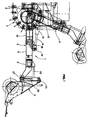
- an implement carrier generally indicated at 1 comprises an arm 2 which is articulated at one end to a frame 3 of a self-propelled vehicle; in the present case a crawler vehicle 4 of known type and therefore not shown in detail.
- the arm 2 carries a fork-like holder 5, which is intended to store a device at its free ends, in the present case a snow blower 6 for preparing ski slopes.
- the articulation of the arm 2 on the vehicle frame 3 is produced by a double-articulated coupling 7, of which one of the joints is formed by a bolt 8 which is arranged perpendicular to the central longitudinal axis of the vehicle 4 and the other joint is produced by a horizontal bolt 9 which is spaced from the bolt 8.
- the bolt 9 is located in the vicinity of the bolt 8 between the same and the end of the arm 2 which carries the holder 5.
- the arm 2 is formed by a hollow profile 10 which is articulated on the bolt 9 and in which a profile 11 is slidably received, which carries the holder 5 at its outer end.
- a hydraulic cylinder 13 is articulated to the frame 3 in 12, the piston rod 14 of which is articulated at its end in 15 to a flange 16 which is fastened to the end of the fixed profile 10 facing away from the bolt 8 .
- joints 17 and 18 are provided which are spaced apart from the longitudinal axis 35.
- a cylinder 19 is articulated on the joint 17, the piston rod of which is articulated in 21 on the outer end of the slidable profile 11.
- a cylinder 22 is articulated, the piston rod of which is articulated in 24 at the end of the profile 11 in such a way that the articulations 21 and 22 are mirror images of the vertical plane passing through the longitudinal axis of the arm 2.
- the two arms 25 and 26 of the holder 5 extend downward symmetrically with respect to one another and at their end pivotably support a frame 28 in 27, the upper support 29 of which is rocker-shaped and on which the milling cutter 6 can be firmly attached.
- the piston rod 30 of a hydraulic cylinder 32 is articulated on the frame 28 in FIG. 31, which in turn is articulated on the flange 33 fixed to the base 34 of the holder 5.
- the cylinders 19 and 22 are expediently connected to a hydraulic system (not shown) of the self-propelled vehicle in such a way that one of the two cylinders is pressurized, while the other cylinder remains unloaded when the arm 2 is to be pivoted about the vertical axis 8 or vice versa . So the cylinders 13 and 32 are also hydraulically connected to the hydraulic system in such a way that the implement carrier can be conveniently controlled by the operator of the self-driving vehicle.
- the device 6, here in the form of a milling cutter, is attached to the frame 28 with appropriate fastening to the same.
- the arm 10 has its longitudinal axis coinciding with the longitudinal axis 35 of the self-driving vehicle. If the self-propelled vehicle is now moved in the direction of travel, the movable profile 11 of the arm 2 is placed in a fully extended position, which is determined by an end stop, not shown, which limits the extraction of the profile 11 itself. In this situation, the piston rods 20 and 23 are approximately halfway through the extension.
- the device carrier is now drawn in the floating position of the device 6 with unloaded cylinders 19 and 22 like a drawbar.
- the piston rod 14 is retracted into the cylinder 13, the telescopic arm 2 being brought into the position 2 'in which the implement carrier is at the stop with the vehicle frame.
- the telescopic arm 2 is either in contact with the cylinder 19 or with the cylinder 22.
- the device carrier according to the invention not only increases the maneuverability of the self-driving vehicle, but also allows a transport characterized by maximum compactness and stability.
Claims (5)
- Support d'appareil pour le montage sur un véhicule automoteur (4), en particulier pour la préparation des pistes de ski, comprenant:- une structure (2) destinée à être articulée, de manière rotative autour d'un axe horizontal (19) et d'un axe vertical (8), sur le châssis (3) du véhicule automoteur (4),- un actionneur relié entre la structure (2) et le châssis (3) du véhicule automoteur (4) et en mesure de causer la rotation de la structure (2) dans un plan vertical,- deux actionneurs (19, 22) qui sont reliés entre ladite structure (2) et le châssis (3) du véhicule automoteur (4) et sont destinés à causer la rotation de la structure dans un plan passant par l'axe horizontal d'articulation, et- un soutien (5) prévu à l'extrémité de la structure (2) opposée à l'extrémité d'articulation de cette structure (2) sur le châssis (3) du véhicule automoteur,la structure étant formée d'un bras (2) articulé sur le châssis du véhicule automoteur à travers un joint de cardan (7) ayant un axe de rotation vertical (8) et un axe de rotation horizontal (9), caractérisé en ce que le bras (2) est télescopique, sur la partie fixe de ce bras étant articulée l'une des extrémités de l'actionneur susceptible de commander les mouvements dans un plan vertical du bras (2) et sur sa partie mobile étant articulée l'extrémité de l'actionner destiné à commander les mouvements du bras (2) dans le plan passant par l'axe horizontal.
- Support (1) d'appareil selon la revendication 1, caractérisé en ce que les actionneurs (19, 22) destinés à effectuer les mouvements du bras (2) dans un plan passant par l'axe horizontal d'articulation (9) sont articulés sur le châssis (3) à des points disposés symétriquement par rapport à l'axe longitudinal (35) du véhicule automoteur (4) et sensiblement à la même hauteur que l'axe horizontal (9) du joint de cardan (7), chaque tige de piston (20, 23) des actionneurs étant articulée sur l'extrémité de la partie mobile (11) du bras (2).
- Support (1) d'appareil selon les revendications précédentes, caractérisé en ce que le joint de cardan (7) a son axe horizontal (9) disposé entre l'axe vertical (8) et l'extrémité exterieure de la partie mobile (11) du bras (2).
- Support (1) d'appareil selon les revendications 1 et 2, caractérisé en ce que le joint de cardan (7) a son axe vertical (8) disposé entre l'axe horizontal (9) et l'extrémité exterieure de la partie mobile (11) du bras (2).
- Support (1) d'appareil selon la revendication 1, caractérisé en ce que le soutien (5) porte un bâti (28) articulé rotativement sur celui-ci, destiné à porter un appareil et susceptible d'être commandé autour de son articulation (27) au moyen d'un cylindre hydraulique (32) agissant entre le soutien (5) et le bâti (28).
Applications Claiming Priority (2)
| Application Number | Priority Date | Filing Date | Title |
|---|---|---|---|
| ITBZ92001 | 1992-01-10 | ||
| ITBZ920001A IT1260303B (it) | 1992-01-10 | 1992-01-10 | Portattrezzi portato da un veicolo semovente, in particolare per la preparazione di piste di sci |
Publications (2)
| Publication Number | Publication Date |
|---|---|
| EP0551160A1 EP0551160A1 (fr) | 1993-07-14 |
| EP0551160B1 true EP0551160B1 (fr) | 1996-08-14 |
Family
ID=11346531
Family Applications (1)
| Application Number | Title | Priority Date | Filing Date |
|---|---|---|---|
| EP93200039A Expired - Lifetime EP0551160B1 (fr) | 1992-01-10 | 1993-01-08 | Support d'appareil pour le montage sur véhicules automoteurs, en particulier pour la préparation des pistes de ski |
Country Status (4)
| Country | Link |
|---|---|
| EP (1) | EP0551160B1 (fr) |
| AT (1) | ATE141363T1 (fr) |
| DE (1) | DE59303384D1 (fr) |
| IT (1) | IT1260303B (fr) |
Cited By (1)
| Publication number | Priority date | Publication date | Assignee | Title |
|---|---|---|---|---|
| EP3613901B1 (fr) * | 2007-10-30 | 2024-02-28 | PRINOTH S.p.A. | Dispositif d'attelage permettant d'atteler un outil de damage de piste de ski à une dameuse et procédé de commande faisant appel à ce dispositif d'attelage |
Families Citing this family (9)
| Publication number | Priority date | Publication date | Assignee | Title |
|---|---|---|---|---|
| FIU960089U0 (fi) * | 1996-02-09 | 1996-02-09 | Kertzen Oy | Laite lumiauran muotoilemiseksi |
| EP1908673B1 (fr) | 2006-10-06 | 2009-12-09 | Rolic Invest Sarl | Véhicule à chenilles |
| ITMI20071249A1 (it) | 2007-06-21 | 2008-12-22 | Rolic Invest Sarl | Rampone per cingoli di veicoli cingolati, in particolare veicoli battipista |
| ITMI20072091A1 (it) | 2007-10-30 | 2009-04-30 | Rolic Invest Sarl | Fresa rotante da neve e metodo per la preparazione del manto nevoso delle piste da sci |
| ITMI20072102A1 (it) | 2007-10-31 | 2009-05-01 | Rolic Invest Sarl | Fresa rotante da neve per la preparazione del manto nevoso delle piste da sci |
| ITMI20072105A1 (it) | 2007-10-31 | 2009-05-01 | Rolic Invest Sarl | Fresa rotante da neve per la preparazione del manto nevoso delle piste da sci |
| ITMI20081001A1 (it) | 2008-05-29 | 2009-11-30 | Rolic Invest Sarl | Cingolo per veicoli battipista e veicolo battipista provvisto di tale cingolo |
| IT1394923B1 (it) | 2009-02-18 | 2012-07-27 | Rolic Invest Sarl | Veicolo battipista comprendente un gruppo verricello di ausilio alla movimentazione del veicolo battipista lungo pendii ripidi e metodo di azionamento del gruppo verricello |
| RU2506173C1 (ru) * | 2012-10-08 | 2014-02-10 | Открытое акционерное общество "Инновационная фирма "НАМИ-Сервис" (ОАО "НАМИ-Сервис") | Модуль силового узла сцепного устройства и сцепное устройство с таким модулем (варианты) |
Family Cites Families (5)
| Publication number | Priority date | Publication date | Assignee | Title |
|---|---|---|---|---|
| AU530693B2 (en) * | 1979-09-27 | 1983-07-28 | Petitto Mine Equip Repair | Underground material handling vehicle |
| DE3247971A1 (de) * | 1982-12-24 | 1984-06-28 | Karl Kässbohrer Fahrzeugwerke GmbH, 7900 Ulm | Schneefahrzeug zur loipenpflege |
| AT379756B (de) * | 1983-07-15 | 1986-02-25 | Bombardier Rotax Wien | Nachziehbares pisten- bzw. loipenpflegegeraet |
| DE8632321U1 (fr) * | 1986-12-03 | 1987-01-29 | Karl Kaessbohrer Fahrzeugwerke Gmbh, 7900 Ulm, De | |
| US5142800A (en) * | 1991-12-27 | 1992-09-01 | Logan Manufacturing Company | Snow groomer tow frame alignment device |
-
1992
- 1992-01-10 IT ITBZ920001A patent/IT1260303B/it active IP Right Grant
-
1993
- 1993-01-08 AT AT93200039T patent/ATE141363T1/de active
- 1993-01-08 EP EP93200039A patent/EP0551160B1/fr not_active Expired - Lifetime
- 1993-01-08 DE DE59303384T patent/DE59303384D1/de not_active Expired - Fee Related
Cited By (1)
| Publication number | Priority date | Publication date | Assignee | Title |
|---|---|---|---|---|
| EP3613901B1 (fr) * | 2007-10-30 | 2024-02-28 | PRINOTH S.p.A. | Dispositif d'attelage permettant d'atteler un outil de damage de piste de ski à une dameuse et procédé de commande faisant appel à ce dispositif d'attelage |
Also Published As
| Publication number | Publication date |
|---|---|
| ITBZ920001A1 (it) | 1993-07-11 |
| DE59303384D1 (de) | 1996-09-19 |
| IT1260303B (it) | 1996-04-05 |
| ATE141363T1 (de) | 1996-08-15 |
| ITBZ920001A0 (it) | 1992-01-10 |
| EP0551160A1 (fr) | 1993-07-14 |
Similar Documents
| Publication | Publication Date | Title |
|---|---|---|
| EP0633185B1 (fr) | Remorqueur d'avion pour barre de remorquage | |
| CH683170A5 (de) | Schreitfahrzeug. | |
| DE1944214B2 (de) | Chienenlos verfahrbarer drehkranunterwagen | |
| CH650299A5 (de) | Schreitbagger. | |
| EP0394534A1 (fr) | Remorqueur d'avion sans barre de remorquage (palette tournante) | |
| EP0551160B1 (fr) | Support d'appareil pour le montage sur véhicules automoteurs, en particulier pour la préparation des pistes de ski | |
| EP0059409A2 (fr) | Véhicule à moteur, notamment tracteur agricole | |
| EP0065118B1 (fr) | Excavatrice | |
| DE7338262U (de) | Landwirtschaftliche arbeitsmaschine | |
| EP1077306B1 (fr) | Machine de travaux mobile | |
| DE4110265C2 (fr) | ||
| DE1482111A1 (de) | Anbauvorrichtung fuer den Seitenanbau von landwirtschaftlichen Geraeten an einen Ackerschlepper | |
| AT11609U1 (de) | Harvester | |
| EP2088243B1 (fr) | Flèche d'un dispositif de lancement d'un véhicule de pose de pont et procédé de déplacement d'une flèche dans une position de transport de véhicule | |
| EP0270096B1 (fr) | Véhicule de pistes avec porteur d'outils | |
| DE2615497C3 (de) | Zugdeichselanordnung für schleppergezogene landwirtschaftliche Maschine | |
| DE2414098A1 (de) | Drillmaschine | |
| EP1655450B1 (fr) | Appareil de forage | |
| DE2928278A1 (de) | Front- oder hecklader | |
| DE19620944C1 (de) | Abstützeinrichtung mit Querbewegungsantrieb für mobile Arbeitsgeräte | |
| DE19708316A1 (de) | Fahrbares Arbeitsgerät | |
| EP2357287B1 (fr) | Véhicule de travail doté d'au moins un cadre de montage | |
| DE1174702B (de) | Lademaschine mit zwei hintereinanderliegenden und miteinander verbundenen Parallelogramm-fuehrungen fuer das Arbeitsgeraet | |
| EP0330818B1 (fr) | Machine pour la fenaison | |
| DE2852938C2 (de) | Fahrzeug fuer den transport von schweren hohlkoerpern, insbesondere fertiggaragen |
Legal Events
| Date | Code | Title | Description |
|---|---|---|---|
| PUAI | Public reference made under article 153(3) epc to a published international application that has entered the european phase |
Free format text: ORIGINAL CODE: 0009012 |
|
| AK | Designated contracting states |
Kind code of ref document: A1 Designated state(s): AT BE CH DE ES FR GB LI NL SE |
|
| 17P | Request for examination filed |
Effective date: 19930917 |
|
| 17Q | First examination report despatched |
Effective date: 19950224 |
|
| GRAH | Despatch of communication of intention to grant a patent |
Free format text: ORIGINAL CODE: EPIDOS IGRA |
|
| GRAH | Despatch of communication of intention to grant a patent |
Free format text: ORIGINAL CODE: EPIDOS IGRA |
|
| GRAA | (expected) grant |
Free format text: ORIGINAL CODE: 0009210 |
|
| AK | Designated contracting states |
Kind code of ref document: B1 Designated state(s): AT BE CH DE ES FR GB LI NL SE |
|
| PG25 | Lapsed in a contracting state [announced via postgrant information from national office to epo] |
Ref country code: NL Free format text: LAPSE BECAUSE OF FAILURE TO SUBMIT A TRANSLATION OF THE DESCRIPTION OR TO PAY THE FEE WITHIN THE PRESCRIBED TIME-LIMIT Effective date: 19960814 Ref country code: GB Effective date: 19960814 Ref country code: ES Free format text: THE PATENT HAS BEEN ANNULLED BY A DECISION OF A NATIONAL AUTHORITY Effective date: 19960814 |
|
| REF | Corresponds to: |
Ref document number: 141363 Country of ref document: AT Date of ref document: 19960815 Kind code of ref document: T |
|
| REG | Reference to a national code |
Ref country code: CH Ref legal event code: NV Representative=s name: KELLER & PARTNER PATENTANWAELTE AG |
|
| REF | Corresponds to: |
Ref document number: 59303384 Country of ref document: DE Date of ref document: 19960919 |
|
| PG25 | Lapsed in a contracting state [announced via postgrant information from national office to epo] |
Ref country code: SE Effective date: 19961114 |
|
| ET | Fr: translation filed | ||
| PG25 | Lapsed in a contracting state [announced via postgrant information from national office to epo] |
Ref country code: BE Effective date: 19970131 |
|
| NLV1 | Nl: lapsed or annulled due to failure to fulfill the requirements of art. 29p and 29m of the patents act | ||
| GBV | Gb: ep patent (uk) treated as always having been void in accordance with gb section 77(7)/1977 [no translation filed] |
Effective date: 19960814 |
|
| PLBE | No opposition filed within time limit |
Free format text: ORIGINAL CODE: 0009261 |
|
| STAA | Information on the status of an ep patent application or granted ep patent |
Free format text: STATUS: NO OPPOSITION FILED WITHIN TIME LIMIT |
|
| 26N | No opposition filed | ||
| PGFP | Annual fee paid to national office [announced via postgrant information from national office to epo] |
Ref country code: CH Payment date: 20021219 Year of fee payment: 11 |
|
| PGFP | Annual fee paid to national office [announced via postgrant information from national office to epo] |
Ref country code: DE Payment date: 20021230 Year of fee payment: 11 |
|
| PG25 | Lapsed in a contracting state [announced via postgrant information from national office to epo] |
Ref country code: LI Free format text: LAPSE BECAUSE OF NON-PAYMENT OF DUE FEES Effective date: 20040131 Ref country code: CH Free format text: LAPSE BECAUSE OF NON-PAYMENT OF DUE FEES Effective date: 20040131 |
|
| PG25 | Lapsed in a contracting state [announced via postgrant information from national office to epo] |
Ref country code: DE Free format text: LAPSE BECAUSE OF NON-PAYMENT OF DUE FEES Effective date: 20040803 |
|
| REG | Reference to a national code |
Ref country code: CH Ref legal event code: PL |
|
| PGFP | Annual fee paid to national office [announced via postgrant information from national office to epo] |
Ref country code: FR Payment date: 20120202 Year of fee payment: 20 |
|
| REG | Reference to a national code |
Ref country code: AT Ref legal event code: MK07 Ref document number: 141363 Country of ref document: AT Kind code of ref document: T Effective date: 20130108 |
|
| PGFP | Annual fee paid to national office [announced via postgrant information from national office to epo] |
Ref country code: AT Payment date: 20120110 Year of fee payment: 20 |