EP0550855A2 - Electrical cable clamping device with cable foil grounding means - Google Patents
Electrical cable clamping device with cable foil grounding means Download PDFInfo
- Publication number
- EP0550855A2 EP0550855A2 EP92121435A EP92121435A EP0550855A2 EP 0550855 A2 EP0550855 A2 EP 0550855A2 EP 92121435 A EP92121435 A EP 92121435A EP 92121435 A EP92121435 A EP 92121435A EP 0550855 A2 EP0550855 A2 EP 0550855A2
- Authority
- EP
- European Patent Office
- Prior art keywords
- cable
- clamp
- foil
- clamping device
- bus terminal
- Prior art date
- Legal status (The legal status is an assumption and is not a legal conclusion. Google has not performed a legal analysis and makes no representation as to the accuracy of the status listed.)
- Withdrawn
Links
- 239000011888 foil Substances 0.000 title claims abstract description 63
- 239000004020 conductor Substances 0.000 claims abstract description 73
- 230000013011 mating Effects 0.000 claims abstract description 23
- 230000000149 penetrating effect Effects 0.000 claims abstract description 15
- 230000000295 complement effect Effects 0.000 claims abstract description 6
- 230000008878 coupling Effects 0.000 claims description 6
- 238000010168 coupling process Methods 0.000 claims description 6
- 238000005859 coupling reaction Methods 0.000 claims description 6
- 239000000463 material Substances 0.000 claims description 3
- 238000009413 insulation Methods 0.000 description 8
- 239000002131 composite material Substances 0.000 description 5
- 238000006073 displacement reaction Methods 0.000 description 4
- 230000000712 assembly Effects 0.000 description 3
- 238000000429 assembly Methods 0.000 description 3
- 239000003989 dielectric material Substances 0.000 description 3
- 238000005253 cladding Methods 0.000 description 2
- 230000035515 penetration Effects 0.000 description 2
- 230000005855 radiation Effects 0.000 description 2
- 230000005540 biological transmission Effects 0.000 description 1
- 230000000694 effects Effects 0.000 description 1
- 239000011810 insulating material Substances 0.000 description 1
- 230000007935 neutral effect Effects 0.000 description 1
- 230000002093 peripheral effect Effects 0.000 description 1
- 238000010079 rubber tapping Methods 0.000 description 1
Images

Classifications
-
- H—ELECTRICITY
- H01—ELECTRIC ELEMENTS
- H01R—ELECTRICALLY-CONDUCTIVE CONNECTIONS; STRUCTURAL ASSOCIATIONS OF A PLURALITY OF MUTUALLY-INSULATED ELECTRICAL CONNECTING ELEMENTS; COUPLING DEVICES; CURRENT COLLECTORS
- H01R12/00—Structural associations of a plurality of mutually-insulated electrical connecting elements, specially adapted for printed circuits, e.g. printed circuit boards [PCB], flat or ribbon cables, or like generally planar structures, e.g. terminal strips, terminal blocks; Coupling devices specially adapted for printed circuits, flat or ribbon cables, or like generally planar structures; Terminals specially adapted for contact with, or insertion into, printed circuits, flat or ribbon cables, or like generally planar structures
- H01R12/50—Fixed connections
- H01R12/59—Fixed connections for flexible printed circuits, flat or ribbon cables or like structures
- H01R12/61—Fixed connections for flexible printed circuits, flat or ribbon cables or like structures connecting to flexible printed circuits, flat or ribbon cables or like structures
- H01R12/613—Fixed connections for flexible printed circuits, flat or ribbon cables or like structures connecting to flexible printed circuits, flat or ribbon cables or like structures by means of interconnecting elements
- H01R12/616—Fixed connections for flexible printed circuits, flat or ribbon cables or like structures connecting to flexible printed circuits, flat or ribbon cables or like structures by means of interconnecting elements having contacts penetrating insulation for making contact with conductors, e.g. needle points
-
- H—ELECTRICITY
- H01—ELECTRIC ELEMENTS
- H01R—ELECTRICALLY-CONDUCTIVE CONNECTIONS; STRUCTURAL ASSOCIATIONS OF A PLURALITY OF MUTUALLY-INSULATED ELECTRICAL CONNECTING ELEMENTS; COUPLING DEVICES; CURRENT COLLECTORS
- H01R12/00—Structural associations of a plurality of mutually-insulated electrical connecting elements, specially adapted for printed circuits, e.g. printed circuit boards [PCB], flat or ribbon cables, or like generally planar structures, e.g. terminal strips, terminal blocks; Coupling devices specially adapted for printed circuits, flat or ribbon cables, or like generally planar structures; Terminals specially adapted for contact with, or insertion into, printed circuits, flat or ribbon cables, or like generally planar structures
- H01R12/50—Fixed connections
- H01R12/59—Fixed connections for flexible printed circuits, flat or ribbon cables or like structures
- H01R12/65—Fixed connections for flexible printed circuits, flat or ribbon cables or like structures characterised by the terminal
- H01R12/67—Fixed connections for flexible printed circuits, flat or ribbon cables or like structures characterised by the terminal insulation penetrating terminals
- H01R12/675—Fixed connections for flexible printed circuits, flat or ribbon cables or like structures characterised by the terminal insulation penetrating terminals with contacts having at least a slotted plate for penetration of cable insulation, e.g. insulation displacement contacts for round conductor flat cables
Definitions
- This invention generally relates to the art of electrical connectors and, particularly, to a cable clamping device for use with an electrical connector for electrically terminating conductors of a multi-conductor cable and to ground a shielding foil of the cable.
- Electrical connector assemblies are available for multi-conductor cables and which include an elongated housing having a cable terminating face.
- the housing has a plurality of contacts or terminals therein, the contacts having respective conductor receiving portions extending from the face, such as insulation displacement conductor terminating portions.
- the connector assembly also may include an elongated cable clamping cover assembly having latch means engaging complementary latch means on the housing to retain the cover assembly against the cable terminating face of the housing.
- the cover assembly has a through passage for receiving the conductors and aperture means which receive the conductor receiving portions of the contacts.
- Such connector assemblies are used, for example, in a communication system wherein it may be desirable to tap a peripheral device into the cable of an existing system.
- An example of such an electrical connector assembly is shown in U.S. Patent No. 4,668,039 to Marzili, dated May 26, 1987.
- This invention is directed to providing an electrical connector assembly which includes a cable clamping cover assembly or device for facilitating enhanced grounding of a shielding foil.
- An object, therefore, of the invention is to provide a new and improved electrical cable clamping device for use in an electrical connector assembly and which includes a novel clamping and grounding means for a shielding foil of the cable.
- a cable clamping device for use with an electrical connector for electrically terminating conductors of a multi-conductor cable.
- the cable includes a ground conductor and a shielding foil running the length of the cable.
- the cable clamping device includes at least a pair of clamp members hingedly attached and defining mating faces profiled to provide a cable passage therebetween, and complementary interengaging latch means on the clamp members hold the members together sandwiching the cable in the passage.
- a foil shield bus terminal be provided on one of the clamp members and including puncture means for penetrating the shielding foil.
- Means are provided on the other of the clamp members for biasing the shielding foil into penetrating engagement with the puncture means.
- Conductive means are provided for coupling the foil shield bus terminal to the ground conductor of the cable.
- the other of the clamp members is a "split member" providing a pair of clamping portions. One clamping portion is hingedly attached along one side of the one clamp member for clamping the conductors of the cable therebetween, and the other clamping portion is hingedly attached to the one clamp member along an opposite thereof for biasing the shielding foil into penetrating engagement with the puncture means.
- the entire cable clamping device is unitarily molded of dielectric material such as plastic or the like, and the two clamping portions are hingedly attached to the one clamp member by integral "living" hinges.
- the puncture means on the foil shield bus terminal are provided in the form of serrated teeth, and the means for biasing the shielding foil into penetrating engagement with the puncture means is provided in the form of a recessed area in the other clamp member for receiving the serrated teeth.
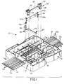
- Figures 1-3 show an electrical connector, generally designated 10, and Figures 4 and 5 show a cable clamping device, generally designated 12, which when assembled together provide an electrical connector assembly for terminating conductors of a multi-conductor flat cable, generally designated 13 in Figure 1.
- Multi-conductor flat cable 13 includes a plurality of generally parallel discrete conductors surrounded by insulation and joined by an insulating web, as is generally known in the art. Cable 13 is shown in phantom in the area of electrical connector 10 so as not to block a view of the connector itself.
- the cable includes three power conductors 13a (i.e. neutral, ground and hot conductors) and a plurality of data conductors 13b.
- electrical connector 10 includes a generally rectangular or square housing, generally designated 14, having a cable terminating face 16 and an opposite mating face 18.
- terminating face 16 is recessed within sidewalls 18 of the housing to provide a recessed area for receiving cable clamping device 12.
- Latch arms 22, having latching apertures 22a project outwardly from terminating face 16, within the recessed area of sidewalls 18, for latching the cable clamping device to the housing, as described hereinafter.
- a plurality of terminals are mounted within housing 14 for insulation-displacing termination with power conductors 13a of cable 13. Although only one terminal 24 is shown in Figure 1, there will be three such terminals corresponding to the three power conductors.
- Each terminal 24 has mating contact portions 28 at opposite ends thereof and located behind a respective pair of a plurality of openings 30 (Fig. 2) in mating face 18 for receiving complementary contacts from an appropriate mating connector. As shown, each contact portion 28 is a female receptacle for receiving a complementary pin or blade contact from the mating connector plugged into connector 10 through openings 30. The contact portions 28 are press-fit into sockets 31 in the rear terminating face of housing 14 as seen in Figure 1. Each terminal 24 also has a terminating portion 32.
- the terminating portion provides an insulation displacement means for terminating a respective power conductor 13a of flat multi-conductor 13 by piercing the insulation of the cable, as is known in the art.
- the terminating portions 32 of terminals 24 project rearwardly from cable terminating face 16 of housing 14 of electrical connector 10.
- the electrical connector also includes a plurality of terminals, generally designated 34 (only one of which is shown in Fig. 1), which also project from cable terminating face 16 for terminating data conductors 13b of cable 13. Openings 31 (Fig. 2) in mating face 18 receive prongs of appropriate plug connectors for connection to female receptacle portions 34a of terminal means 34.
- the receptacle portions 34a are press-fit into sockets 35 in rear terminating face 16 of housing 14.
- Each terminal 34 also includes a terminating portion 34b at each opposite end thereof, projecting from terminating face 16, for terminating a respective data conductor 13b of cable 13 by piercing the insulation of the cable, as is known in the art.
- a "bridging" conductive member is provided for coupling a foil shield of cable 13 to a particular one of conductors 13a or 13b which comprises a ground conductor.
- bridging conductive member 36 has a terminating portion 37 of the insulation displacement type for terminating the ground conductor.
- the bridging conductive member also has a projecting bifurcated portion 38 for purposes described hereinafter.
- cable clamping device 12 includes a pair of clamp members, generally designated 40 and 42, which are hingedly attached and define mating faces 40a and 42a, respectively.
- Recessed areas 44 and 46 in mating face 40a of clamp member 40, and recessed areas 48 and 50 in mating face 42a of clamp member 42 combine, when the clamp members are closed in the direction of arrow "A" (Fig. 4), to define a cable receiving passage means 41a and 41b between the clamp members when in closed condition as shown in Figure 5.
- a multi-conductor flat cable such as cable 13 may include power conductors 13a separated transversely of the cable from data conductors 13b, and all of the conductors are joined by an insulating web of the cable.
- the data conductors would be disposed in through passage means 41b defined by recessed areas 46 and 50 of clamp members 40 and 42, respectively, and the power conductors would be disposed in the through passage means 41a defined by recessed areas 44 and 48 of clamp members 40 and 42, respectively.
- Recessed areas 44 and 46 of clamp member 40 are divided by a raised rib 52, and recessed areas 48 and 50 of clamp member 42 are divided by a raised rib 54, all of which is best seen in Figure 4.
- Latch means are provided on clamp members 40 and 42 to hold the members together sandwiching flat cable 13 therebetween in through passages 41a and 41b. More particularly, a latch arm 56, having an elongated aperture 58, projects from clamp member 42. Latch detents 60a and 60b are located in an opening 62 in clamp member 40. The latch detents have tapered camming surfaces which will engage latch arm 56 when the clamp members are closed. It can be seen that latch detent 60a is closer to mating face 40a of clamp member 40 than are latch detents 60b. This allows for a preassembled condition of clamped members 40 and 42, i.e. whereby latch arm 56 first will snap behind latch detent 60a to slightly space the clamp members, and further latching engagement will cause the latch arm to latch behind latch detents 60b to fully close the clamp members.
- Cable clamping device 12 also includes latch means for assembling the device to electrical connector 10 (Figs. 1-3). More particularly, latch detents 64 are provided in openings 66 in clamp members 40 and 42 for receiving apertured latch arms 22 (Figs. 1 and 3) of electrical connector 10.
- cable clamping device 12 is unitarily molded of dielectric material such as plastic or the like and including latch arm 56 projecting from mating face 42a of clamp member 42. Therefore, the latch arm is flexible for snapping over latch detents 60a, 60b on clamp member 40.
- housing 14 of electrical connector 10 is unitarily molded of dielectric material such as plastic or the like and latch arms 22 similarly are flexible for snapping over latch detents 64.
- clamp members 40 and 42 are hingedly attached for clamping movement toward each other in the direction of arrow "A" (Fig. 4). Normally, clamp member 42 will be closed onto clamp member 40, with flat cable 13 first layed into recesses 44 and 46 of clamp member 40.
- hinge means are provided by integral living hinge sections 74 joining the clamp members whereby the hinge sections bend as seen in Figure 5 when the clamp members are moved from their opened condition to their closed condition.
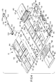
- multi-conductor cable 13 has been shown as part of a composite cable system, generally designated 80, which has an outer tubular insulating covering or sheath 82.
- the covering has been cut, as at 84, and multi-conductor cable 13 has been laid-out into a flat configuration for positioning in recessed areas 44 and 46 of clamp member 40 which define passage means 41a and 41b (Fig. 5).
- a shielding foil 86 of the cable has been separated from the multi-conductor flat cable and moved to one side thereof.
- the invention contemplates coupling the shielding foil to a ground conductor of the cable.
- a third clamp member 88 is hingedly attached to clamp member 40 by integral living hinge means 90 similar to hinge portions 74 between clamp members 40 and 42.
- Clamp member 88 is pivotable about hinge means 90 in the direction of arrow "B" from an opened position shown in Figure 4 to a closed position as shown in Figure 5.
- a flexible latch arm 92 projects from a mating face 94 of clamp member 88 and includes an aperture 96 for snapping over a chamfered latch detent 98 in opening 62 in clamp member 40, on a side of opening 62 opposite latch detents 60a and 60b. Consequently, when clamp member 80 is closed onto clamp member 40, latch arm 96 and latch detent 98 hold the clamp members in closed condition sandwiching shielding foil 86 therebetween.
- a foil shield bus terminal is generally elongated and includes two pairs of depending tabs 102 for press-fitting into openings 104 in mating face 40a of clamp member 40.
- Serrations or teeth 106 project upwardly from bus terminal 100 and provide puncture means for penetrating shielding foil 26.
- the serrated teeth are provided at opposite ends of the bus terminal. Therefore, when clamp member 88 is closed onto clamp member 40, it is intended to drive the serrated teeth in penetrating engagement with shielding foil 86.
- a pair of generally rectangular recesses including side portions 108 and end portions 110, are molded into mating face 94 of clamp member 88. Side portions 108 of the recesses are provided for receiving serrated teeth 106 of bus terminal 100 as mating face 94 of clamp member 88 engages the sheet-like foil.
- conductive means are provided for coupling the foil, through bus terminal 100, to a ground conductor of multi-conductor cable 13.
- bridging conductive member 36 is provided for this purpose.
- the bridging conductive member includes a bifurcated portion 38. This portion projects upwardly through an opening 112 in clamp member 40, through an opening 114 in bus terminal 100 and into an opening 116 in clamp member 88 when the clamp member is closed. It can be seen in Figures 1 and 3 that bifurcated portion 38 is pointed so that it easily can penetrate any portion of shielding foil 86 which overlies opening 114 in bus terminal 100.
- bifurcated portion 38 of bridging conductive member 36 is press-fit into opening 114 in the bus terminal to establish good conductivity within the opening so that conductivity between the bridging conductive member and the foil can be established through the bus terminal, itself, and its penetrating engagement with the shielding foil by means of serrated teeth 106.
- a base portion 120 of bridging conductive member 36 extends transversely from bifurcated portion 38 and terminates in terminating portion 37.
- the terminating portion penetrates the insulation of cable 13 and establishes conductivity with a ground conductor of the grouping of data conductors 13b.
- base portion 120 can extend further transversely of housing 14 for insulation-displacement termination with a ground conductor of power conductors 13a.
- clamp member 88 When properly positioned, clamp member 88 then can be closed and latched onto the shielding foil to effect penetration of the foil by means of the puncturing means afforded by serrated teeth 106.
- the pair of clamp members 42 and 88 which are operatively associated with the single clamp member 40 can be replaced by a second single clamp member to simultaneously clamp multi-conductor flat cable 13 as well as shielding foil 86, within various concepts of the invention.
- some composite cables 80 also have a drain wire 130 running lengthwise of the cable within outer insulating covering 82. This drain wire also can be coupled to ground by means of bus terminal 100.
- a notched flange 132 is provided transversely across each opposite end of bus terminal 100.
- the notches in the flanges are provided for receiving the drain wire.
- End portions 110 of the rectangular recesses in mating face 94 of clamp member 88 are provided for receiving notched flanges 132 when clamp member 88 is closed onto clamp member 40.
- the flat surface of mating face 94 and an area 134 within side portions 108 and end portions 110 all facilitate penetration of the shielding foil by serrated teeth 106 and the positioning of drain wire 130 into notched flanges 132.
Landscapes
- Multi-Conductor Connections (AREA)
- Coupling Device And Connection With Printed Circuit (AREA)
- Connections By Means Of Piercing Elements, Nuts, Or Screws (AREA)
Applications Claiming Priority (2)
| Application Number | Priority Date | Filing Date | Title |
|---|---|---|---|
| US817181 | 1992-01-06 | ||
| US07/817,181 US5174782A (en) | 1992-01-06 | 1992-01-06 | Electrical cable clamping device with cable foil grounding means |
Publications (2)
| Publication Number | Publication Date |
|---|---|
| EP0550855A2 true EP0550855A2 (en) | 1993-07-14 |
| EP0550855A3 EP0550855A3 (enExample) | 1994-01-12 |
Family
ID=25222519
Family Applications (1)
| Application Number | Title | Priority Date | Filing Date |
|---|---|---|---|
| EP92121435A Withdrawn EP0550855A2 (en) | 1992-01-06 | 1992-12-17 | Electrical cable clamping device with cable foil grounding means |
Country Status (3)
| Country | Link |
|---|---|
| US (1) | US5174782A (enExample) |
| EP (1) | EP0550855A2 (enExample) |
| JP (1) | JPH0760713B2 (enExample) |
Cited By (3)
| Publication number | Priority date | Publication date | Assignee | Title |
|---|---|---|---|---|
| DE4402837A1 (de) * | 1994-01-31 | 1995-08-03 | Daetwyler Ag | Flachkabel |
| EP0727851A3 (en) * | 1995-02-15 | 1997-10-08 | Sumitomo Wiring Systems | Electrical connection structure between an electrical connection box and an electronic circuit unit |
| DE19946468A1 (de) * | 1999-09-28 | 2001-05-03 | Tyco Electronics Logistics Ag | Verbindungsvorrichtung zur Verbindung von zwei Flexleitungen |
Families Citing this family (20)
| Publication number | Priority date | Publication date | Assignee | Title |
|---|---|---|---|---|
| US5509812A (en) * | 1994-06-20 | 1996-04-23 | Molex Incorporated | Cable tap assembly |
| US5791933A (en) * | 1994-08-23 | 1998-08-11 | Sumitomo Wiring Systems, Ltd. | Wiring construction of electrical connection box |
| US5658164A (en) * | 1995-03-24 | 1997-08-19 | The Whitaker Corporation | Flexible flat electrical cable connector with a conductive shield |
| US5727971A (en) * | 1996-05-21 | 1998-03-17 | The Whitaker Corporation | Shielded cable assembly |
| US5967832A (en) * | 1998-02-23 | 1999-10-19 | 3M Innovative Properties Company | High speed connector assembly |
| DE19844869A1 (de) * | 1998-09-30 | 2000-05-11 | Alcatel Sa | Kontaktelement zur Verbindung einer Flachbandleitung mit Rundleitern und Drehverbinder mit einem derartigen Kontaktelement |
| US6139358A (en) * | 1999-02-09 | 2000-10-31 | Hon Hai Precision Ind. Co., Ltd. | Ground plane cable connector assembly |
| US6398581B1 (en) * | 2000-12-19 | 2002-06-04 | American Standard Inc. | Bus connector and method for integrating electrical test points in the bus connector |
| AU2002356986A1 (en) * | 2001-11-21 | 2003-06-10 | Woodhead Industries, Inc. | Molded electrical connector |
| US6837737B2 (en) | 2002-10-10 | 2005-01-04 | American Standard International Inc. | Bus connector |
| JP4632980B2 (ja) * | 2006-03-16 | 2011-02-16 | モレックス インコーポレイテド | 中継コネクタ |
| DE202008008696U1 (de) * | 2008-06-28 | 2009-11-19 | Weidmüller Interface GmbH & Co. KG | Anschlussvorrichtung für Mehrleiterkabel |
| US8444431B1 (en) * | 2011-11-18 | 2013-05-21 | Tyco Electronics Corporation | Insulation piercing connector assemblies and methods and connections including same |
| JP6039487B2 (ja) * | 2013-04-05 | 2016-12-07 | 矢崎総業株式会社 | コネクタ |
| US9287673B2 (en) * | 2013-12-06 | 2016-03-15 | Tyco Electronics Corporation | Insulation piercing connectors and methods and connections including same |
| JP6397647B2 (ja) * | 2014-04-09 | 2018-09-26 | 新電元工業株式会社 | コネクタ |
| SE539322C2 (en) * | 2015-11-18 | 2017-07-04 | Roxtec Ab | Transition and module |
| US10840615B2 (en) | 2018-06-28 | 2020-11-17 | Te Connectivity Corporation | Connection enclosure assemblies, connector systems and methods for forming an enclosed connection between conductors |
| US11431114B2 (en) | 2020-02-14 | 2022-08-30 | Te Connectivity Solutions Gmbh | Enclosed connection systems for forming an enclosed connection between conductors, and methods including same |
| EP3989378B1 (en) | 2020-10-20 | 2024-11-20 | Hyster-Yale Materials Handling, Inc. | Clamp for elongate objects |
Family Cites Families (10)
| Publication number | Priority date | Publication date | Assignee | Title |
|---|---|---|---|---|
| US3934075A (en) * | 1974-02-26 | 1976-01-20 | E. I. Du Pont De Nemours And Company | Clip for shielded multiconductor flat cable |
| US4068912A (en) * | 1977-02-25 | 1978-01-17 | Amp Incorporated | Cable clamping insulation displacing electrical connector for multi-conductor flat flexible cable |
| US4458967A (en) * | 1982-01-15 | 1984-07-10 | Cooper Industries, Inc. | Connector for shielded flat cable |
| US4500157A (en) * | 1982-09-21 | 1985-02-19 | Amp Incorporated | Mounting and grounding clamp for shielded cable |
| US4492815A (en) * | 1983-08-23 | 1985-01-08 | Cooper Industries, Inc. | Shielded jacketed flat cable and grounding clip for use therewith |
| US4678864A (en) * | 1985-06-27 | 1987-07-07 | Cooper Industries, Inc. | Mass terminable flat cable assembly with readily separable ground plane |
| DE3784955T2 (de) * | 1986-01-27 | 1993-09-02 | Whitaker Corp | Verkettungsverbinder. |
| DE3619370A1 (de) * | 1986-06-09 | 1987-12-10 | Siemens Ag | Verfahren und anordnung zur kontaktierung von geschirmten flachbandkabeln |
| US4997388A (en) * | 1989-08-28 | 1991-03-05 | Amp Incorporated | Electrical tap connector |
| US5038001A (en) * | 1990-03-13 | 1991-08-06 | Amp Incorporated | Feature for orientation of an electrical cable |
-
1992
- 1992-01-06 US US07/817,181 patent/US5174782A/en not_active Expired - Fee Related
- 1992-12-17 EP EP92121435A patent/EP0550855A2/en not_active Withdrawn
- 1992-12-22 JP JP4356806A patent/JPH0760713B2/ja not_active Expired - Lifetime
Cited By (7)
| Publication number | Priority date | Publication date | Assignee | Title |
|---|---|---|---|---|
| DE4402837A1 (de) * | 1994-01-31 | 1995-08-03 | Daetwyler Ag | Flachkabel |
| EP0665608A3 (de) * | 1994-01-31 | 1996-12-04 | Daewyler Ag Kabel Und Systeme | Elektrisches Installationssystem. |
| DE4402837C2 (de) * | 1994-01-31 | 1998-08-06 | Daetwyler Ag | Elektrisches Installationssystem, gebildet durch Flachkabel und Anschlußvorrichtung |
| EP0727851A3 (en) * | 1995-02-15 | 1997-10-08 | Sumitomo Wiring Systems | Electrical connection structure between an electrical connection box and an electronic circuit unit |
| US5759050A (en) * | 1995-02-15 | 1998-06-02 | Sumitomo Wiring Systems, Ltd. | Electrical connection construction between electrical connection box and electronic circuit unit |
| DE19946468A1 (de) * | 1999-09-28 | 2001-05-03 | Tyco Electronics Logistics Ag | Verbindungsvorrichtung zur Verbindung von zwei Flexleitungen |
| DE19946468C2 (de) * | 1999-09-28 | 2002-03-21 | Tyco Electronics Logistics Ag | Verbindungsvorrichtung zum Verbinden von zwei Flexleitungen |
Also Published As
| Publication number | Publication date |
|---|---|
| EP0550855A3 (enExample) | 1994-01-12 |
| US5174782A (en) | 1992-12-29 |
| JPH0760713B2 (ja) | 1995-06-28 |
| JPH05275129A (ja) | 1993-10-22 |
Similar Documents
| Publication | Publication Date | Title |
|---|---|---|
| US5174782A (en) | Electrical cable clamping device with cable foil grounding means | |
| US4653825A (en) | Shielded electrical connector assembly | |
| US4884981A (en) | Shielded data connector | |
| US4602831A (en) | Electrical connector and method of making same | |
| EP0632541B1 (en) | Electrical connector for high density ribbon cable | |
| US4317608A (en) | Slotted pate terminal for stranded wire | |
| EP1003250B1 (en) | A shield connector, a set of shielded connectors and method for connecting a shielded connector with a shielded cable | |
| JP3775557B2 (ja) | コネクタ | |
| US4682840A (en) | Electrical connection and method of making same | |
| EP0602539B1 (en) | Electrical connector assembly with terminal alignment system | |
| CA1068364A (en) | Flat conductor cable connector | |
| EP0653815B1 (en) | Electrical connector with cable shield ground clip | |
| US6068505A (en) | Electrical contact for flexible flat cable | |
| CA1198789A (en) | Electrical plug connector | |
| EP0014037A1 (en) | Electrical connector for flat cable | |
| US5133672A (en) | Insulation displacement terminal | |
| JPH07122306A (ja) | 圧接ジョイントコネクタ | |
| CA2234654C (en) | Branch connector apparatus | |
| EP0125760A1 (en) | Connector plug having shielding enclosure | |
| US5464352A (en) | Electrical connector assembly | |
| US4564256A (en) | Flat cable transition connector | |
| US6036535A (en) | Cable end cap for power cable tap connector | |
| JP3697231B2 (ja) | プラグコネクタ | |
| US4990102A (en) | Electrical connector having a secondary cable strain relief and a strain relief member therefor | |
| US6483035B2 (en) | Protecting configuration for flat cables |
Legal Events
| Date | Code | Title | Description |
|---|---|---|---|
| PUAI | Public reference made under article 153(3) epc to a published international application that has entered the european phase |
Free format text: ORIGINAL CODE: 0009012 |
|
| AK | Designated contracting states |
Kind code of ref document: A2 Designated state(s): DE FR GB IT |
|
| PUAL | Search report despatched |
Free format text: ORIGINAL CODE: 0009013 |
|
| AK | Designated contracting states |
Kind code of ref document: A3 Designated state(s): DE FR GB IT |
|
| 17P | Request for examination filed |
Effective date: 19940601 |
|
| STAA | Information on the status of an ep patent application or granted ep patent |
Free format text: STATUS: THE APPLICATION HAS BEEN WITHDRAWN |
|
| 18W | Application withdrawn |
Withdrawal date: 19940824 |